Xilinx XC7K410T-2FFG676i Technical Detail

Xilinx XC7K410T-2FFG676i

The Xilinx XC7K410T-2FFG676i FPGA belongs to the Kintex-7 family and is available in different speed grades such as -2L, -1L, -1, -2, and -3. The -3-speed grade is with the highest possible performance. Whereas, -2L speed grade is preferred to be utilized for applications where requirements for low maximum possible static power are required. This device is capable of operating in low core voltages. The industrial temperature devices of -2L are capable of operating at VCCINT to be 0.95V only. The extended temperature devices of -2L can perform at VCCINT=0.9V and sometimes at 1.0V too. The devices of -2LE speed grade can perform at VCCINT=1.0V. The devices of -2LI can operate at VCCINT=0.95V. The specifications for -2LI devices are almost the same as that for -2 devices with an exception of some points. The dynamic power, static power, and speed consideration are reduced for -2LE devices when these operate in the VCCINT to be 0.9V. The military temperature devices -1L are having the same speed consideration as that for -1 military temperature devices.

The Xilinx XC7K410T-2FFG676i AC and DC features are divided into temperature ranges of commercial, expanded, industrial, military, and extended. An exception is considered for the operating temperature range, apart from that all of its AC and DC characteristics and electrical parameters are similar for a specific speed grade device. For example, characteristics of timing for devices of -1 speed grade are the same as for -1 devices of commercial temperature speed grade. Nevertheless, a selected range of devices or their speed grades is available for every range of temperature. For instance, -1Q is available for the Kintex-7 XA family and -1M is available only for the Kintex-7 defense-grade family.

Absolute Maximum Rating of Xilinx XC7K410T-2FFG676i

If any stress or force is applied to the Xilinx XC7K410T-2FFG676i device beyond mentioned absolute maximum rating may or may not result in damaging the IC forever. Furthermore, constant and regular exposure of the device to its absolute maximum ratings may also result in its non-reliable performance. For the device, its lower absolute voltage specifications are also always applied. The maximum possible limit of the device applies to DC signals and its minimum and maximum overshoot and undershoot specifications for AC voltages must be considered. Following thermal and soldering guidelines are also important to get the maximum benefit out of the device.

Recommended Conditions of Operation

FULL PCB MANUFACTURING Quote

There are certain recommended operating conditions for Xilinx XC7K410T-2FFG676i which must be followed such as the voltages applied must be relative to ground. For designing the system of power distribution, pin planning, and PCB design guides must be consulted. The VCCBRAM and VCCINT must have a connection to the same point of the same supply. The data of configuration is retained in the device even if VCCO has dropped to 0V. The supported VCCO ranges of the device comprise 3.3V, 1.2V, 2.5V, 1.35V, 1.8V, and 1.5V. The specifications for lower absolute voltages must also be followed for the device. For each bank of the device, the current must not exceed 200mA. The VCCBATT is only needed when bitstream encryption is utilized. In case of the battery is not utilized, then VCCBATT must be connected to VCCAUX or GND. A filtering circuit is required for every voltage range that is listed and for the data rates above 10.3125 Gb/s, VMGTAVCC must be equivalent to 1.0V to consume less power. Furthermore, for less power consumption, VMGTAVCC must also be 1.0V for the entire frequency range of CPLL.

Power Supply Sequence of Xilinx XC7K410T-2FFG676i

There is a specific powering ON sequence required for the Xilinx XC7K410T-2FFG676i that is starting with VCCINT, followed by VCCBRAM, VCCAUX, VCCAUX_IO, and ends at VCCO. This is how the device can minimum possible drawl of current for ensuring the inputs/outputs to be at 3-state during power ON condition. The power OFF sequence is in reverse to that of the power ON condition. In case if VCCBRAMย and VCCINTย are having similar voltages that are recommended then both of them could be powered through the same supply. Now, if the VCCO, VCCAUX_IO, and VCCAUXย are having similar voltages that are recommended then both can be in power ON status through the same supply and can also be ramped together.

The Measurements of Output Delay

The delays at the output of the Xilinx XC7K410T-2FFG676i device are measured with minor output traces. The device is making use of a standard termination for testing. The propagation delay of traces is considered distinctly and then deducted from the measurements that are finalized. This is why the measurement mechanism is not included in the generic test setup for the device. Different parameters such as VMEAS, VREF, CREF, and RREF are describing the testing conditions of every input/output standard. The precise prediction for the propagation delay through a given application is being obtained through the simulation in the IBIS tool. The simulation is conducted in a specific way such that the output driver of a specific choice is to be simulated into a generalized test setup through the use of various values. The VMEAS is to be recorded. The output driver must be simulated into traces of PCB and then loaded through the utilization of an appropriate model at IBIS or with the value of capacitance representing the load. After that VMEAS must be recorded.

Performance of GTX Transceiver

VCCINT is the specified voltage for all speed grades of the device Xilinx XC7K410T-2FFG676i. the devices of -1 speed grade are requiring an internal data width of 4 bytes for its operation beyond 5.0 Gb/s. The device of -2LE speed grade is requiring an internal data width of 4 bytes for its operation beyond 3.8 Gb/s. However, the data rates for the devices are not available among 8.0 Gb/s up to 9.8 Gb/s. The line rates that are beyond 10.3125 Gb/s, the VMGTAVCC is to be 1.05V at the nominal case.

Specifications of XADC

The gain and offset errors are eradicated by enabling the XADC gain through the calibration feature of Xilinx XC7K410T-2FFG676i. However, the values are only specified after the feature is enabled. In case of a variation in reference voltages from any of its nominal values VREFN is to be OV and VREFP is to be 1.25V to result in a slight change from the ideal transfer function. This is also supposed to impact the precision of the measurements of internal sensors such as power supply and temperature.

Xilinx XC7K160T-2FFG676i FPGA Price

Xilinx XC7K160T-2FFG676i

The Xilinx-7 FPGA series Xilinx XC7K160T-2FFG676i consists of a total of 4 families namely spartan-7, Artix-7, Kintex-7, and Virtex-7. This FPGA is manufactured based on higher-end technology with low power consumption capabilities and an unmatched increase in the performance of the system. This IC has a state-of-the-art FPGA logic that is grounded on a lookup table of 6 inputs which may be configured in the form of distributed memory. With its integrated FIFO logic enabled 36Kb block RAM, it can do data buffering on-chip. The rapid speed serial connectivity along with integrated numerous gigabit transceivers that range from 600Mb/s till 28.05 Gb/s offers a dedicated mode for low power consumption. The DSP slices have a total of 25×18 multipliers along a high-tech pre-adder for filters, an accumulator of 48 bits. Xilinx XC7K160T-2FFG676i has outstanding clock management tiles, a mixed-mode clock manager, and a phase-locked loop for greater accuracy and less jitter.

Electrical Characteristics of Xilinx XC7K160T-2FFG676i

The single-ended outputs of the device are utilizing a traditional CMOS pull/push structure at its output that drives in HIGH mode at VCCO and a LOW mode towards GND. This can also be put into a HIGH-Z state. The designer of the system is capable of specifying output strength and its slew rate too. Its input is always in active mode; however, it is often ignored whenever its output is active. Every of its pin may or may not have an optional pull-down or pull-up resistor. Most of the pairs of pins of Xilinx XC7K160T-2FFG676i could be configured in the form of a differential output or input pairs. The input pair of pins can also be ended along 100 Ohms resistor. Entire families of this device are supporting differential standards that go beyond differential HSTL, BLVDS, differential SSTL, LVDS, and RSDS. Every of its input/output is supporting standards of memory input/output like differential and single-ended HSTL.

Out-Of-Band Signaling

The transceivers of the Xilinx XC7K160T-2FFG676i are offering out-of-band signaling that is more often utilized for sending lower-speed signals from the transmitter to that of the receiver. Whereas, the higher speed transmission of serial data is not in active mode. This is conventionally achieved at a time when a link is in the form of power-down mode. It can also be achieved when a link is not yet initialized.

Built-in Interfaces for PCI Express Design

There are numerous built-in blocks for various interfaces in Xilinx XC7K160T-2FFG676i such as block for compliance to PCI express base with specifications of 3.0 or 2.1 along with the capability of root-port and endpoint. These blocks are supporting different generations such as Gen1 of 2.5 Gb/s, Gen2 of 5 Gb/s, and Gen3 of 8 Gb/s. There are various high-tech configuration options such as end-to-end CRC error detection, and high-tech error reporting. All of the families of devices i.e., Virtex-7, Kintex-7, and Artix-7 are comprising of an integrated block for the technology of PCI express that has the capability for root port and endpoint. The Xilinx is offering an IP wrapper that is light in weight, easy to utilize, and configurable too tying numerous building blocks for clocking resources, block RAM, transceivers, and PCI express. The designer of the system is capable of having control over numerous configurable parameters such as filtering, decoding register for base address, the clock frequency of reference, interface speeds of FPGA logic, highest payload size, and lane width.

Partial Reconfiguration, Readback, and Encryption

FULL PCB MANUFACTURING Quote

In almost all of the Xilinx XC7K160T-2FFG676i series, the bitstream of FPGA is consisting of sensitive customer IP. This IP is protected with AES technology of 256-bit encryption along with an authentication mechanism of SHA-256 for prevention against illegal design piracy. FPGA is performing decryption while the configuration is in progress through an internally installed battery-enabled RAM. The configuration data could be read back irrespective of having an impact on the operation of the system. Usually, the configuration is known as all an all or nothing operation but in Xilinx XC7K160T-2FFG676i series devices partial support is given to configuration. This feature is powerful and is flexible too allowing users to make changes in different parts of FPGA keeping all other parts in a static position.

Analog to Digital Converter

Xilinx XC7K160T-2FFG676i has an analog to digital converter having numerous features comprising of a 12-bit dual-mode single MSPS analog to digital converter. The ADC is having over 17 user-configurable and flexible analog inputs. There is an option for external reference and an on-chip temperature sensor with ยฑ4ยฐC accuracy. There is non-stop JTAG access to all of the measurements taken by analog to digital converter. Almost all of the devices of the Xilinx-7 family have a built-in analog to digital converter interface designated as XADC. When the XADC is combined with the capability of programming logic, it is capable of addressing a vast range of monitoring and data acquisition requirements.

The XADC of Xilinx XC7K160T-2FFG676i is consisting of a 12-bit single MSPS analog to digital converter having a separate track for holding amplifiers along with an on-chip multiplexer, supply, and thermal sensors. Both of the ADCs could be configured collectively for sampling the two external-input channels of analog mode. The hold and track amplifier are supporting a wide range of analog input types of signals comprising of differential, bipolar, and unipolar types. The analog inputs are capable of supporting signals with a bandwidth of almost 500 kHz at a sampling rate of over 1 MSPS. The possibility of supporting higher bandwidth is also possible through the utilization of a multiplexer at its external side along with a dedicated analog input. The XADC is utilizing an on-chip circuit for referencing optionally. This is eliminating any requirement for an external component in an active state for primary on-chip monitoring of power supply rails and temperature.

Easy Path-7 of Xilinx XC7K160T-2FFG676i

The EasyPath-7 is delivering a very fast, risk-free, and simple solution for making reductions in costs for Virtex-7 and Kintex-7 family designs. This is also supporting the same speed grades, packages, and is matching the entire range of Kintex-7 and Virtex-7 specifications when timing and functioning are considered. Irrespective of any requalification and re-engineering, EasyPath-7 is delivering the lowest possible product cost when compared to any other competitor FPGA.

What is Xilinx XC7K160T-2FBG484i Fpga?

Xilinx XC7K160T-2FBG484i

Introduction

The Xilinx XC7K160T-2FBG484i is a Kintex-7 series field programmable gate array (FPGA) providing high performance, capacity, and bandwidth. This mid-range family balances power, performance and cost for high-end embedded applications.

Key features of this FPGA include:

  • 163,200 logic cells with 6-input look-up tables
  • On-chip memory of nearly 10Mb
  • 2800 DSP slices for intensive signal processing
  • High speed transceivers reaching 10Gbps
  • Advanced power management options
  • High logic capacity in a space saving BGA package

This article provides an in-depth look at the XC7K160T architecture, characteristics, applications, design considerations, and frequently asked questions surrounding use of this popular Xilinx FPGA.

XC7K160T Family Overview

The Xilinx Kintex-7 family offers high performance FPGAs featuring both high logic capacity and high speed connectivity suitable for wireless, medical, video, and military applications.

The XC7K160T device specifically provides:

  • 163,200 logic cells in 6-input LUTs
  • 218 DSP slices with 27×18 multipliers
  • On-chip memory of 9.9Mb
  • Dual channel 1062Mb/s DDR3 memory interface
  • 2800 Mb/s data transfer rate per I/O
  • High speed serial transceivers up to 10.3Gb/s
  • 1.0V core voltage and 2.5V I/O voltage
  • Operating temperature range of 0ยฐC to +100ยฐC
  • Space saving 23mm x 23mm 484 ball BGA package
  • Static power of 2W and total power less than 10W

This balance of high logic capacity, DSP, memory blocks, and I/O in an efficient package make the XC7K160T suitable for advanced embedded systems.

XC7K160T FPGA Architecture

Xilinx Artix 7
Xilinx Artix 7

The Xilinx Kintex-7 family uses a unified FPGA architecture to efficiently implement designs requiring both advanced digital signal processing and high speed connectivity. It is optimized for applications such as wireless infrastructure, medical imaging, semiconductor test, military video processing, and machine vision.

Key architectural features include:

Configurable Logic Blocks (CLBs): Each CLB contains two slices, each with four 6-input LUTs and 8 flip-flops. LUTs can also be configured as 64-bit RAM or shift registers. There are 32600 CLB slices containing the bulk of the FPGA’s logic capacity.

DSP Slices: 218 27×18 bit multipliers enable intensive DSP functions. Features include cascading, optional pipeline registers, and dedicated ALUs to avoid routing congestion.

Block RAM: Over 9Mb of distributed block RAM provide on-chip data storage. 36Kb blocks support a range of width/depth configurations with ECC options.

I/O: The FPGA offers 550 high performance I/O supporting up to 2800Mb/s. Support for common I/O standards like LVDS, PCIe, SATA, and memory interfaces.

Transceivers: Integrated serial transceivers reach speeds up to 10.3Gbps, with lower power versions at 3.2Gbps. Support various protocols including Ethernet, Interlaken, and PCI Express.

Clock Management Tiles (CMT): 10 CMTs provide clock synthesis, conditioning, and jitter filtering.

This combination of high capacity, high performance blocks makes this an optimal FPGA for advanced embedded systems.

XC7K160T-2FBG484i Characteristics

The XC7K160T-2FBG484i denotes specific device characteristics within the broader XC7K160T family:

  • Temperature Range: The 2F version supports an extended 0ยฐC to +100ยฐC industrial temperature range for more demanding environments.
  • Package: This FPGA utilizes a space saving 23mm x 23mm body size, 1.0mm ball pitch 484 ball grid array (BGA) package. Provides highest I/O density in this device class.
  • Speed Grade and Power: Designated speed grade -2, with maximum static power rating of 2W. Dynamic power consumption is device dependent but less than 10W total.
  • Configuration: SRAM-based which loads programming from external memory on power up. Remote system update capability.
  • Part Marking: Xilinxโ€™s marking format for this exact device prints as XC7K160T FFG484 – 2 along with additional manufacturing codes on the chip top side.

So in summary, the XC7K160T-2FBG484i is the Kintex-7 FPGA with 163K logic cells, packaged in a 484 pin BGA, speed grade -2, extended temperature range, SRAM configured.

Key Applications of the XC7K160T

The Xilinx XC7K160T FPGA fits well in high performance embedded systems requiring a balance of digital logic, signal processing, and high speed connectivity.

Some of the key application areas include:

Wireless Communications: Mid-range logic density supports base stations and infrastructure processing data intensive protocols like LTE. Integrated DSP slices and transceivers are optimized for wireless systems.

Medical Imaging: Ultrasound, MRI, and CT scan systems leverage the FPGAโ€™s ability to process large data sets combined with high speed interfaces.

Video Processing: Surveillance, machine vision, and video conferencing systems take advantage of the XC7K160Tโ€™s 1080p video performance and image processing capabilities.

Semiconductor Testing: High pin count, fast data rates, and timing features support automated test equipment for semiconductor production environments.

Aerospace and Defense: Ruggedized designs for mission computing, instrumentation and sensors benefit from logic capacity, reliability and extended temperature range.

Scientific Instrumentation: High performance embedded systems used in research rely on the raw processing power, flexibility, and I/O bandwidth of devices like the XC7K160T.

This FPGA hits the sweet spot for many applications needing a balanced feature set, high performance, and proven architecture.

XC7K160T vs Konkurrenz’s Comparable FPGAs

The Xilinx XC7K160T resides between competing FPGAs from other vendors in terms of density and capability:

FPGA FamilyKey Comparable DeviceLogic CellsTransceiversDSP Slices
Xilinx Kintex-7XC7K160T163K16218
Altera Stratix V5SGXEA7K2F40C2254K24256
Lattice ECP5LFE5UM-85F85K080
Microchip PolarFireMPF300TS120K16312
QuickLogic EOS S3EOS S3-L13K080

So the XC7K160T hits a middle ground between lower cost FPGAs and very high density Stratix/Virtex families. This balanced density, features, and cost make it attractive for many applications.

Key Design Considerations with the XC7K160T

Xilinx FPGA distributor

Engineers should keep several design considerations in mind when working with the XC7K160T FPGA:

  • Utilization – At 163K logic cells, designs over 100K usage require analysis to ensure timing, power, and congestion goals are met.
  • Thermal – With 10W max power, proper board airflow or heatsinks are needed. Thermal simulation should be performed.
  • Decoupling – Numerous power pins require proper decoupling for stability. Plan for bulk and localized decoupling.
  • ESD Protection – FPGAs are highly ESD sensitive. Robust protection diodes, pads, and handling controls must be used.
  • Design Flows – Xilinx offers strong tool flows – ISE, Vivado, Vitis – leveraging FPGA optimizations and IP libraries.
  • Debugging – Plan for debug access through JTAG, internal probes, logic analyzers. ChipScope integrated tools are useful.

Properly planning for utilization, thermal, ESD, debug, and taking advantage of Xilinx design tools ensures success with this FPGA.

How to Get Started with the XC7K160T

Xilinx provides excellent documentation and development kits to jumpstart XC7K160T designs:

  • Product Specification – Data sheet contains comprehensive technical reference information on the FPGA.
  • Documentation Navigator – Central area to access device user guides, application notes, white papers, reference designs, and training material.
  • Kintex-7 GTX Transceiver User Guide – In-depth guide to implementing high speed serial I/O.
  • Vivado Design Suite – Xilinxโ€™s flagship design environment with FPGA-optimized implementation tools.
  • KCU105 Evaluation Kit – Full platform to develop and evaluate designs. Includes board, power supply, memory module, cables, and documentation.

Engineers should leverage these resources when starting new XC7K160T-based projects.

Conclusion

The Xilinx XC7K160T-2FBG484i FPGA delivers an optimal balance of high capacity, performance, and features for advanced embedded systems. With 163K logic cells, abundant memory blocks, DSP slices, fast serial transceivers, and dense I/O, this versatile FPGA services a wide range of applications. Engineers require FPGA skills and Xilinx-specific expertise to fully utilize the capabilities. Following recommended design practices and using Xilinx development kits accelerates success leveraging the XC7K160T in next generation systems.

Frequently Asked Questions

What are the main differences between Kintex-7 and Virtex-7 FPGA families?

Key differences:

  • Density – Virtex-7 offers up to 2M logic cells, significantly higher than Kintex-7
  • Performance – Virtex-7 clock speeds, DSP slices, SERDES are faster
  • Cost – Virtex devices are most expensive, aimed at top performance
  • Power – Virtex max TDP up to 30W, Kintex-7 just 10W
  • Package – Virtex utilizes high-pin BGA packages, Kintex-7 more compact
  • Certification – Virtex has more rigorous qualification for aerospace/defense

So in essence, Virtex-7 is very high performance while Kintex-7 balances capability and cost.

What are the most important specs for evaluating an FPGA?

Key specifications include:

  • Logic cells – Determines capacity for digital logic and routing
  • Block memory – On-chip data storage avoids external memories
  • DSP blocks – Enable high throughput arithmetic operations
  • Maximum transceiver speed – Essential for high speed interfaces
  • Package footprint – Impacts board layout and routing
  • Temperature range – Industrial grade required for some applications
  • Static power – Lower power extends battery life

The requirements depend on the target application of the FPGA.

What are the easiest ways to get started with FPGA development?

Recommendations to begin FPGA development:

  • Use vendor evaluation kits – These provide full out-of-box development platforms
  • Download design tools – Take advantage of vendor tool ecosystems with optimizations
  • Follow board user guides – Accelerate learning proper implementation
  • Run demo projects – Modifying examples is faster than new designs
  • Take online training – Tool specific and FPGA courses shorten the learning curve
  • Engage tech support – FPGA vendor FAEs can mentor new users

Jumping right into tools, kits, and examples gets new FPGA developers productive quickly.

What types of designers work with FPGAs?

Typical designers using FPGAs include:

  • Digital logic designers – Implement logic gates, state machines, algorithms
  • Hardware engineers – Interface FPGAs to processors, memory, converters
  • Embedded software developers – Program the integrated soft processors
  • DSP engineers – Develop complex signal processing blocks
  • PCB layout designers – Layout, route, and debug FPGA boards
  • Systems engineers – Manage IP selection, partitioning, co-design
  • Application engineers – Map product features to optimized FPGA logic

FPGAs therefore require multi-disciplinary systems expertise to properly apply.

What makes Xilinx FPGAs unique?

Some unique advantages of Xilinx FPGAs:

  • Large ecosystem of third party IP libraries
  • Long history as the pioneer in FPGAs
  • Unified, regular architecture for efficiency
  • Advanced tool suite with unique features
  • Highest performance transceivers
  • Comprehensive product portfolio
  • Wide range of development kits and boards
  • Strong integration between software and hardware

These factors together provide compelling benefits versus competitors.

How to Choose PCB Capacitor ?

PCB Capacitor

There can be discrete capacitors present along with the PCB capacitor. This may function as capacitors that are lumped. This is suitable because it can be used in creating a system of distribution for your top-quality design.

What is a PCB Capacitor?

Printed circuit boards can function like capacitors. This is because capacitors could be composed of two objects made of metal, put apart by a material that is non-dielectric. Therefore, combining PCB components, pads, pins, and tracks, should transform into a capacitor that will be able to destabilize frequency oscillation.

Asides from this, power and grand planes offer the necessary decoupling capacitance. You can even utilize capacitors at your PCBโ€™s edges. You only need to get two good copper planes. This would serve as capacitors. Then we can go ahead to get discrete capacitors coupled with the capacitor of the PCB. This may function like lumped capacitors, which youโ€™ll utilize in creating a system for distributing your design.

Decoupling Capacitor

FULL PCB MANUFACTURING Quote

The effectiveness of your design is dependent on some factors. This includes how the decoupling capacitors affect the printed circuit boards. Typically, this plan comes with a top and bottom layer located on the chipโ€™s sides. You connect the vias to the ground and the power plane. The connection of the full capacitors must be done to the ground plane (unbroken) due to the fact that it has some benefits.

Their impedance level is usually the lowest. Unfortunately, if you are searching for signals of high frequency, the arrangement may fail to work. You must have a good layout. This ensures that routing doesnโ€™t find its way into some other movements. Therefore, it is very necessary that your design features two-layer boards.

Non PCB Capacitor

In 1979, PCB capacitors were banned. This means that the manufacturers had no choice but to have something to replace it. This is the Di2-Ethylhexyl phthalate. The dielectric fluid can be seen in non-PCB ballast capacitors. Presently, there is DEHP in about one-quarter of capacitors.

The Role Embedded Capacitors Play in PCB Design

circuit board capacitor

Capacitors work in a special way. You can easily construct one by making use of aluminum foil sheets. Get two of these sheets and separate them using a shopping bag made of plastic. Next, connect the foil beneath the earth ground to the DC power supplyโ€™s negative terminal, and then connect the upper aluminum foil to the positive terminal of the power supply. Raising the voltage led to both aluminum foil plates to attract each other noisily.

Flux Capacitors Contain Layers Too

The capacitors that we make use of in our printed circuit board designs are usually different compared to the capacitor built in any studentโ€™s classroom. Before you design the circuit boards, you must know the different properties of the different types of capacitors. This will help in the planning, as well as the design.

If you are working with surface mounted and through-hole designs, you can choose capacitors using the design libraries. This choice is made based on the combination of different attributes, which includes rated voltage, nominal value tolerance, dielectric type, temperature coefficient, and capacitance.

Through-hole mounting has assumed a secondary status to the surface mount technology. However, drilling of holes and the securing of the component leads radially or axially via the board, will add some value for some specific applications. Industrial, aerospace, and military applications need reliability whenever components are subjected to environmental and mechanical stress. The types of THM capacitor are ceramic discs (non-polarized), plastic film, silver mica, coupled with tantalum and polarized electrolytic types.

The surface mount (SMT) type of capacitors do not need hole drilling through the layers. They will also mount to the PCBโ€™s surface directly. Through-hole leads are replaced by the vials, which permits a conducting connection between the circuit board layers. The SMT capacitors mount to the two sides of the board. They also have small packages compared to the Through-hole mounting (THM) capacitors. The types of SMT capacitors include multilayer ceramic, tantalum, mica, electrolytic, and film capacitors.

Embedded Capacitors, Signals, and Circuit Boards

Today, well-known capacitors from history have taken up major roles in surface mount technology PCBs. Looking at the few capacitor types available explains how the capacitor technology has developed from the past till today and has also made an impact into the PCB design future.

There are several benefits of surface mount capacitors. These include low spurious inductance, automated assembly, and small size. Similar features were seen with older through-hole mounting types of capacitors. This offers many advantages for designers of PCB that work with SMT.

Embedded Circuit Boards and Components Now

Materials for embedded capacitance are made of a dielectric material that is usually very thin. Also, they are sandwiched between two copper layers. During the process of manufacturing, an epoxy material coating helps in laminating the copper foils. Capacitors that are embedded into the flex or rigid PCB substrate below an integrated circuitโ€™s pin, usually have their electrical paths very short, which reduces the parasitic inductance and capacitance, and minimizes the EMI.

Due to the increase in capacitive density, the embedded capacitors could become a decoupling capacitor. Therefore, it can ensure the removal of capacitors that are discrete. When you combine these capabilities with the size reduction, embedded capacitors have become very valuable for handheld, medical, computing, and telecommunications equipment.

Smaller footprints for products have become very important. This importance has begun a revolution in the technologies of capacitors. The next step has to do with high density development, solid ultra-thin aluminum capacitors, which provide stability in high-temperature, high-voltage applications, as well as the circuits powering them.

One other electrolytic ultrathin supercapacitor functions for RF applications and microprocessor operating with low power. Designed as components that are embedded, the supercapacitors will offer a very long power life. This is to prepare for the next generation internet of things (IoT) devices, coupled with resisting shock and vibration.

Different Types of Capacitors

capacitor in pcb

Ceramic Capacitors

These capacitors are dielectric in nature, and are made from ceramic materials. Ceramic capacitors usually have small values as their capacitance. This value usually ranges between 1F to 1ยตF. Their capacitors have great frequency response. Also, they are never prone to the effects of parasites.

Ceramic capacitors of class 1 provide low loss, accuracy, and high stability. Their nominal value tolerance can fall within the 1% range. Ceramic operators of class 2, come with greater capacitance values. However their thermal stability is lesser and their nominal value tolerances are less sensitive. Ceramic capacitors operating with large power feature a maximum capacity of 100ยตF. Also, they can deal with much higher voltages, which could get to as high as 100 kV.

MLCC โ€“ Multilayer Ceramic Capacitors

These capacitors account for a large number of capacitors utilized on the surface mount printed circuit boards (PCBs) of today. All MLCC are made up of silver palladium that are interleaved or silver electrodes that are plated with nickel covered with tin (plated) and then interweaved. The dielectric type used when manufacturing the MLCCs has an effect on thermal stability and capacitance.

Capacitors that have a calcium zirconate or titanium oxide dielectric feature a lower capacitance. They also have some thermal characteristics that are very stable. When working with PCB applications involving high-frequency circuits that work with time constant, choose the high-temperature, low capacitance MLCC. The MLCCs having Barium titanate dielectric provides the high capacitance required for power supply decoupling and smoothing.

Note that the MLCCsโ€™ high capacitance balances against the dielectricโ€™s properties. Over time, thereโ€™s a change in the Barium titanate dielectric with the input of voltage.

MLCC capacitors feature low resistance. Due to this, they encounter few issues with the generated heat by resistance. Also, the capacitors offer a great ripple resistance.

Mica Capacitors

They function like ripple filters and decoupling capacitors in power conversion, coupling, time constant, and resonance circuits. Mica capacitors are built from mica sheets, with both sides being coated with metal that is deposited.

SMT and THM mica capacitors offer great stability, reliability, and precision. Their nominal value tolerances are either +-1%, +-2%, or +-5%.

Plastic Film Capacitors

This type of capacitor utilizes different dielectric materials. These materials segment these components for some specific applications. These include general decoupling, coupling, and filtering. Metalized film capacitors like Mylar, as well as other different polystyrene and polyester capacitors are made up of a thin metal layer, which is deposited in a plastic film connecting each lead. The film foil type of capacitors like the PTFE โ€“polytetrafluoroethylene capacitor utilizes plastic films in separating the two electrodes made with metal foil.

FCN Capacitors

This type of capacitor features a metalized non-inductive polyethylene naphthalate film construction, which offers a similar frequency characteristics and stable temperature that are found in the traditional capacitors made of polyester film. The FCN capacitors usually have low ESR. This is why it yields a high-frequency and superior performance.

Due to this, FCN capacitors function for output filtering, power supply input, signal coupling, and EMI filtering.

Type FCP Polyphenylene Sulfide (PPS) Stacked Metalized Film Capacitors

This type of capacitor has high values for their capacitance. Also, over a wide range of temperatures, their high-frequency response is excellent. Just like FCP capacitors, the Type FCA film capacitors (acrylic) provides values of high capacitance couples with a much better high-frequency filtering. Their bus noise attenuation is excellent too. FCA capacitors are composed of alloy terminals plated with copper and metalized resin film having stacked layers that are non-inductive.

Tantalum Capacitors

These capacitors utilize a thin oxide file on tantalum, which is used like an electrolytic. As the oxide layer covers the tantalum anode, and functions like the dielectric, there is a conductive cathode that envelopes the anode and the dielectric.

Though tantalum capacitors lack the present capacity seen in the aluminum electrolytic capacitors, the tantalum capacitors provide stability, endurance, and a high capacitance between 1ยตF and 100ยตF. SMT tantalum capacitors offer similar properties. This also includes a wide range of operating temperatures.

Aluminum Electrolytic Capacitors

This type of capacitor provides a much higher capacitance compared to other types of capacitors. However, their values for nominal tolerance are very wide. Higher values for higher capacitance make way for ripples to be smoothened by electrolytic capacitors whenever it is utilized in power supplies, and they function like coupling capacitors.

As a result of the wide values for tolerance as well as an increase in equivalent series resistance with frequency, the electrolytic capacitors donโ€™t work with high frequencies. Surface mount electrolytic capacitors provide high temperature stability, low impedance and high capacitance.

Asides from this, these SMT electrolytic capacitors can resist vibration properly on non-stationary PCBs โ€“ printed circuit boards.

How do Capacitors Work?

capacitor on pcb

Capacitors are well-known passive components found in circuits. They are similar to the resistors. Capacitors help in storing electrical charge. They also offer different options. This depends on the design of a circuit. The capacitance has to do with the measure of the energy or charge, which can be carried by the capacitor.

When capacitors are in their basic form, they are made of two plates, with an insulator between them.   This insulator is the dielectric. Capacitors are of different types. They are composed of different dielectric materials, and can be utilized for several purposes.

The measurement of capacitance is in Farads. This unit is a fairly large one. This is why it is used generally in microfarads or picofarads. Also, capacitors may also be non-electrolytic or electrolytic. The former may be connected in whatever direction possible in the circuit. For the electrolytic capacitors, you have to install them on the circuit in the right orientation. One of the leads is positive, while the other is negative. The placing of the electrolytic capacitors may not allow your circuits to perform properly. It may even make them pop.

Capacitors may have different applications. One of their critical roles can be found in digital electronics. Here, they protect the microchips from any noise. Due to the fact that the whole charge they carry can be dumped quickly, often they are utilized in lasers and flashes coupled with capacitive sensing and circuit devices. Circuits having capacitors usually display behaviors that are dependent on frequency. This is why they can be utilized on circuits, which amplifies some frequencies.

You can add capacitors either in parallel or in series, just like resistors. However, the calculation is the direct opposite of that of the resistors. The connection of components in series has one node in common. Also, both nodes are shared anytime the connection is in parallel. The resistors connected in series should be added together, if you want to get the total value of the resistance. Also, capacitors having parallel connection should be added, if you need the total value of the capacitance.

Selecting Capacitor Components for your PCB Design

In this section, we will take you through those things you must consider to select electronic components such as capacitors during the designing of your printed circuit board.

New PCB designers will always find it as a challenge when choosing the right electronic components. Choosing these components inappropriately could cause a malfunctioning, a total failure, or an undesired operation of your printed circuit board.

Depending on the component type, there are some important parameters that designers of PCB should consider when choosing the component during the design stage. This section takes you through important consideration for choosing the main electronic components.

How to Choose Capacitors

Capacitors are utilized in different circuits. Choosing the component of your capacitor for your PCB design using just the value for the capacitance is not usually enough in the majority of applications. Just like the resistor components, the capacitors also possess tolerance factors. There is a variation in a capacitor componentโ€™s actual capacitance. This is based on the process of manufacturing, aging, DC biasing, and the operating temperature.

Therefore, the tolerances of the capacitance must be considered when choosing the component for your capacitor. The variation in price between the high and low tolerance capacitors also varies considerably. However, if price isnโ€™t an issue for you, then we advise that you choose a capacitor having a tolerance below 10%. For the majority of low power circuits, having 10% or even 20% as tolerance is sufficient.

What Value of Capacitance will you get?

Damage could come to your capacitor if there is a stress on voltage or the voltage is higher than expected. Most times, capacitors are connected in parallel, either to an output, a sub circuit, or a circuit. The expected drop in voltage across your capacitor should be calculated or known. We recommend that your voltage buffer should be 50% over the expected drop in voltage. This means that, if your expected drop in voltage across your pcb capacitor is 10Volts, then you should choose a capacitor having a 15 volts rated voltage or more.

Lifetime expectancy or the capacitor life can be defined as the time period at which the capacitor remains healthy, and offers capacitance just the way it is designed. It is clear that this is critical, most especially for an electrolytic capacitor. A capacitorโ€™s lifetime under conditions of normal operation is usually given on the productโ€™s datasheet, by the manufacturer.

The capacitorโ€™s temperature for operation ranges. This should be seen just like resistors. Based on the application type, ripple current, and the ECR value, the frequency of operation has to be viewed for designs that are advanced.

Tips on How to Place your PCB Bypass Capacitor

Placing your bypass capacitor could be a very critical phase throughout the process of designing your printed circuit board. Failing to place them the right way could cause a negative performance. Another critical situation is when you have very few capacitors for some components. Whenever cases like this arise, you should communicate the information to the engineer. This will make them update the schematic.

  • Know whether the components should be placed on the boardโ€™s bottom side
  • When many capacitors having different values are given to a supply pin on an integrated circuit, then the capacitor with the lowest value should be placed very close to your device pin.
  • Larger tantalum and non-polarized capacitors has to be placed close to the device or pin from the lowest to the highest value.
  • Devices having many power pins should have one or more bypass capacitors per power pin.
  • Make sure you check the schematic anytime you are placing a bypass capacitor due to the fact that they are usually logic input pins โ€˜tied highโ€™

Disposing Your PCB Capacitor

The disposal of non-PCB capacitors usually requires userโ€™s compliance with the regulations of the federal government, which governs the disposal. Already, a document is available, which presents guidelines to the scrap yards that reveals how this is done.

Crushing and shredding can no longer be used as an alternative. This is because it will contaminate the area where you are doing this. Due to this, removing and storing non-PCB capacitors helps in reducing and preventing you from violating the requirements.

Requirements for Disposal

Alternatively, you can dispose of the capacitors by reaching out to a transporter to help in transporting the PCB waste. In doing this, you must keep proper records. This includes the quantity of drums, the date you picked the haul, the pick-up date, and the name of the transporter.

Conclusion

Take note that decoupling offers reservoir energy to help in smoothing out voltage anytime a change in the amount of current drawn happens. It is normal for the supply of power to take a little time before it responds to the voltage due to inductance. Therefore, the decoupling cap has to close this gap. To achieve this, make sure it is nearer to the digital chip. Otherwise, the inductance of the lead may disrupt things quickly and therefore make it challenging to be able to get additional current quickly.

What is Xilinx XC7A200T-1FBG676C?

Xilinx XC7A200T-1FBG676C

The Xilinx XC7A200T-1FBG676C belongs to the Artix-7 family of low-cost, low-power FPGAs built on 28nm high performance, low power (HPL) process technology. With 200K logic cells, 220 DSP slices and 16.3Gbps transceivers, the XC7A200T provides an ideal blend of programmable logic, signal processing and high-speed connectivity for demanding applications including motor control, automotive driver assistance systems, software defined radio, video bridging, aerospace electronics and test instrumentation.

This article provides an overview of the XC7A200T architecture, available resources, target applications, design flow and benefits for electronics engineers.

XC7A200T-1FBG676C Overview

The XC7A200T represents the higher capacity end of Xilinxโ€™s Artix-7 family of FPGAs optimized for embedded systems requiring substantial programmable logic resources. Key features include:

  • 200K logic cells based on look-up table (LUT) architecture
  • 220 DSP slices with 25×18 multipliers operating at up to 300 MHz
  • Up to 16 gigabit transceivers with data rates up to 16.3Gbps
  • High speed DDR3 external memories supported at up to 1.6Gbps
  • 1650 maximum user I/Os for expansive connectivity
  • MGT and LVDS I/O support for high-performance interfaces
  • Designed for high volume cost-sensitive applications

The 1FBG676 package denotes a 27x27mm 676-pin flip-chip grid array with 1mm ball pitch. This high density form factor provides the ample connectivity an FPGA with 200K logic cells demands.

XC7A200T Internal Architecture

The Artix-7 family architecture balances high density, high performance programmable logic together with essential integrated processing required for advanced embedded systems.

Programmable Logic Fabric

The core programmable logic fabric utilizes Slice architecture containing LUTs, flip-flops, multiplexers and carry logic as the basic building blocks. Key features:

  • 6-input LUTs efficiently implement logic functions using only a single LUT per slice
  • Flip-flops for registering logic outputs or implementing shift registers
  • Arithmetic carry logic for efficient math operations
  • 36Kb Block RAM for on-chip data storage

DSP Slices

220 embedded 18×25 multipliers and 48-bit accumulators enable high-throughput arithmetic and signal processing.

Block RAM

5.3 Mb of distributed 36Kb block RAM provides on-chip data storage with built-in FIFO logic support.

Transceivers

Up to 16 transceivers running at up to 16.3Gbps support high-speed chip-to-chip communications and interfacing.

PCI Express

Two integrated Gen2 PCIe blocks enable direct chip-to-chip communication.

Gigabit Transceivers

Up to 6.6Gbps data rates over differential I/O supports protocols like Ethernet, FibreChannel, Interlaken and Aurora.

XC7A200T Target Applications

The XC7A200T architecture provides an ideal foundation for compute-intensive embedded systems requiring substantial signal processing capabilities:

Motor Control and Servo Drives

  • Industrial servo/motion control
  • Robotics
  • Industrial drives
  • Drone/UAV controllers

Automotive Electronics

  • Surround sensor processing for self-driving
  • RADAR, LiDAR and vision systems
  • Inflight entertainment systems
  • Driver assistance and diagnostics

Communications Infrastructure

  • Wireless baseband processing
  • Microwave and optical link modems
  • High density network cards and switch fabric
  • Software defined radio

Image Processing

  • Machine vision for manufacturing
  • Medical endoscopy and microscopy
  • Video surveillance analytics
  • Optical inspection systems

Aerospace and Defense

  • RADAR and LiDAR processing
  • Avionics equipment
  • Satellite payloads
  • Missile guidance systems

For these demand applications, the XC7A200T enables high throughput parallel processing together with connectivity-centric logic implementation.

XC7A200T-1FBG676C Benefits for Designers

Xilinx Evaluation Board

The XC7A200T provides hardware engineers with several advantages:

High Performance

  • 200K logic cells enables very complex logic implementation
  • 220 high-performance DSP slices for intensive arithmetic processing
  • 16.3Gbps serial connectivity for high-bandwidth chip-to-chip communications

Embedded Processing

  • DSP blocks and transceivers minimize external processing ICs
  • Distributed RAM delivers abundant on-chip data storage

Power Efficiency

  • 28nm process enables low static and dynamic power consumption

Functional Safety

  • Configuration CRCs improves reliability

Cost

  • Mature 28nm process combined with optimized architecture enables low cost

For compute-intensive signal processing applications with complex control logic needs, the XC7A200T provides an ideal FPGA foundation.

XC7A200T Design Flow

Xilinx provides mature development tools for programming the XC7A200T FPGA:

  • Vivado Design Suite – Enables system design, logic synthesis, placement and routing
  • SDSoC Development Environment – Supports embedded software C/C++ programming
  • System Generator – Develops high-performance DSP designs
  • Vivado HLS – Converts C/C++ algorithms into optimized logic implementations
  • Vitis – Unified software platform for embedded software development
  • ChipScope Pro – Provides low-level access for debug

The typical design flow involves:

  1. Create register transfer level (RTL) code defining desired functionality
  2. Run RTL simulations to verify intended design behavior
  3. Synthesize RTL into Xilinx primitives using Vivado synthesis
  4. Place and route design to map into XC7A200T physical resources
  5. Generate bitstream file representing complete FPGA configuration
  6. Program finished bitstream into the XC7A200T device
  7. Validate timing closure and functionality after Place and Route

XC7A200T vs. Larger Kintex-7 FPGAs

Xilinx FPGA distributor

It is useful to contrast the Artix-7 based XC7A200T against the higher capability Kintex-7 FPGAs:

Programmable Logic

  • XC7A200T offers 200K logic cells using 6-input LUTs
  • Kintex-7 provides up to 474K logic cells using 6-input LUTs

Transceivers

  • Both support up to 16 transceivers operating at up to 16.3Gbps

Memory Interfaces

  • Both support 1600Mbps DDR3 interfaces

DSP Slices

  • XC7A200T – 220 slices operating at up to 300MHz
  • Kintex-7 – Up to 3600 slices operating above 500MHz

Cost

  • XC7A200T optimized for high volume cost-driven applications
  • Kintex-7 costs approximately 30-40% higher

For extreme cost-sensitive applications not needing the ultimate logic densities, the Artix-7 based XC7A200T offers a compelling value proposition.

Conclusion

With its high density 6-input LUT fabric, abundant high-performance DSP slices, plentiful RAM and transceivers, the Xilinx XC7A200T-1FBG676C provides hardware designers an extremely capable yet cost-optimized chip foundation for demanding embedded applications including industrial servo control, driver assistance systems, software defined radio, video processing, and aerospace/defense electronics.

For engineers challenged with staying on the cutting edge of connectivity-centric domains requiring both raw processing throughput and flexible programmable logic, the Artix-7 family offers a pin-compatible portfolio scaling from 100K to 350K logic cells to match project needs.

Frequently Asked Questions

Q: What is the Xilinx XC7A200T FPGA?

A: It is a high-end Artix-7 family FPGA with 200K logic cells, 220 DSP slices and 16.3Gbps transceivers, built on a 28nm fabrication process.

Q: What are some key components in the XC7A200T architecture?

A: This includes 200K 6-input LUT logic cells, 220 DSP slices, 5.3Mb of block RAM, up to 16 transceivers, and PCIe blocks, and configurable mixed-voltage I/O.

Q: What are some target applications for the XC7A200T?

A: Motor control, driver assistance systems, wireless infrastructure, aerospace/defense, and video/image processing all leverage the XC7A200T capabilities.

Q: How does XC7A200T compare against Kintex-7 FPGAs?

A: Kintex-7 offers 30-40% higher performance but XC7A200T provides a more cost-optimized solution for many applications.

Q: What tools can be used to program XC7A200T FPGAs?

A: Xilinx’s Vivado, Vitis, and SDSoC tools together enable developing the full system including programmable logic, software, and processing pipelines.

What is Xilinx XC6SLX45T-3CSG324i ?

Xilinx XC6SLX45T-3CSG324i

The Xilinx XC6SLX45T-3CSG324i device belongs to the Spartan-6 family delivering capabilities of system integration along with the lowest costs and supports a large number of applications. The spartan-6 family consists of a total of 13 devices having densities expanded in the range of 3840 till 147443 logic cells and consumes less power when compared to the previous family of similar devices. This device has fast and broad connectivity capabilities. This IC is grounded on the 45nm of lower power consumption technology delivering optimum balance in terms of performance, power, and cost and is offering an efficient dual register enabled lookup table having 6 inputs with a built-in system for a rich selection of different blocks. The blocks are comprising of 18 Kb of blocked rams divided into 2 parts of 9 Kb each.

The device also has 2nd generation DSP slices of DSP48A1, memory controllers of SDRAM, efficient blocks for clock management in mixed-mode, highly optimized power serial transceivers, power management modes, configuration options with auto-detection mode, DNA protection of the device, and efficient IP security enabled with AES. The Xilinx XC6SLX45T-3CSG324i Spartan-6 FPGA has to offer a better solution in terms of higher volume logical design, embedded applications that are cost-sensitive, and DSP design of consumer’s choice. The design of the device is in a way that offers flexibility and effective ways for the designers to focus on innovation by integrating the software and hardware together achieving a specific goal.

Features of Xilinx XC6SLX45T-3CSG324i

FULL PCB MANUFACTURING Quote

Belonging to the Spartan-6 family, the IC has numerous features such as logic optimization, serial connectivity with higher speeds, low-cost design, different blocks integrated together, efficient selection for input/output standards, staggering pads, lower dynamic and static power, and the large quantity of plastic wire-bonded packages. Xilinx XC6SLX45T-3CSG324i has a dedicated mode for hibernation for power down consuming zero power, with suspension mode it maintains the current state and its configurations along with multi-pin wake-up and control enhancement. The device is available in different speed grades like -2, -3, and -3N. The data transferring capabilities of the device is up to 1080 Mb/sec through each differential input/output, the output drive is selectable up to 24mA through each pin. The device has hot-swapped compliance too. It has adjustable slew rates for improving the integrity of signals.

The higher speed interfaces are comprising of XAUI, DisplayPort, GPON, EPON, CPRI, OBSAI, PCI, IG ethernet, Aurora, and serial ATA. The device is enabled with higher performance signal and arithmetic processing. It has to cascade and pipelining capabilities along with integrated memory controller blocks. Xilinx XC6SLX45T-3CSG324i supports data rates up to 800 Mb/sec with a distributed RAM support and an optional shift register. The block ram of the device has a vast granularity range. The digital clock managers of the device are eliminating distortion in duty cycle and clock skew. The phase-locked loops are for lower jitter clocking.

Configuration

The Xilinx XC6SLX45T-3CSG324i spartan-6 FPGA can store configuration in customized data form in the internal latches of SRAM type. The configuration bits are in the range of 3MB to 33MB that depends on the size of the device and implementation options of the user design. The storage of configuration is volatile and is to be reloaded when FPGA is powered up. The configuration is to be reloaded whenever the device is powered OFF and then powered ON. Storage can be reloaded by pulling PROGRAM_B pin to LOW. There are numerous methods available for reloading configuration data. The configurations of bit-serial mode can either be in form of master serial mode in which the FPGA is generating configuration clock signal and its configuration data of external source is also clocking the FPGA.

The configuration information of bitstream in Xilinx XC6SLX45T-3CSG324i is generated through software ISE through a tool known as BitGen. The process of configuration is generally executing the program such that detection of power-up or PROGRAM_B must be in Low, the entire memory configuration is to be cleared, mode pins are sampled for configuration determination in either slave or master mode and parallel or bit-serial mode. The configuration data is to be loaded starting from the detection of bus-width pattern that is followed via synchronization word and checking the proper code of device that is ending through cyclic redundancy check for complete bitstream. The device is intelligent enough to predict which configuration to load next and the time of its loading too. Spartan-6 FPGA Xilinx XC6SLX45T-3CSG324i is comprising of a distinct and DNA identifier that has the purpose of user tracking, IP protection, and anti-cloning of design. The bitstreams of the device are protected using AES encryption.

Readback

Most of Xilinx XC6SLX45T-3CSG324iย configuration data can be read back without affecting the operation of the system.

Configurable Logic Blocks

In Xilinx XC6SLX45T-3CSG324i every of CLB is consisting of two slices that are arranged side-by-side in the form of vertical columns. A total of three sub-types of CLB slices are there in its architecture i.e., SLICEL, SLICEM, and SLICEX. Every slice is having 4 distinct lookup tables and 8 flip-flops with miscellaneous logic. These lookups are of general-purpose and having support for sequential logic. The synthesis tools of the device are taking an advantage of such highly effective logic, memory, and arithmetic features.

Clock Management

Each of the Xilinx XC6SLX45T-3CSG324i devices is having approximately 6 clock management tools, each of which has two digital clock managers with a single-phase lock loop that could be used in cascaded mode or individually.

Phase Shifting

The CLK0 is in connection with CLKFB while the other 9 outputs of the clock could be shifted through a common count by defining an integer with multiples of fixed delay. Whereas, a fixed value of digital clock management can be settled in configuration and can be decremented and incremented too on a dynamic basis.

Clock Distortion

The device is delivering abundant clock lines for addressing various of requirements of clocking for higher fanout, lower skew, and shorter propagation delay.

Global Clock Lines

In every spartan-6 FPGA, Xilinx XC6SLX45T-3CSG324i is having 16 global clock lines with higher fanout and could reach to the clock of the flip-flop. The global clock lines should be driven through buffers of the global clock that can perform multiplexing of the clock without any glitches enabling function of the clock.

What is heat sink in PCB?

Heat Sink PCB

A heat sink is a passive thermal management component that absorbs and dissipates heat generated by electronic components on a printed circuit board (PCB) through thermal conduction. Heat sinks are used to cool components like power transistors, processors, power amplifiers and high-wattage LEDs that produce significant heat during operation.

Effective heat sinking is critical for maintaining device temperatures within safe operating limits and preventing damage or performance degradation. This article provides a comprehensive overview of PCB heat sink materials, design factors, attachment methods and thermal modeling considerations.

Heat Sink Basics

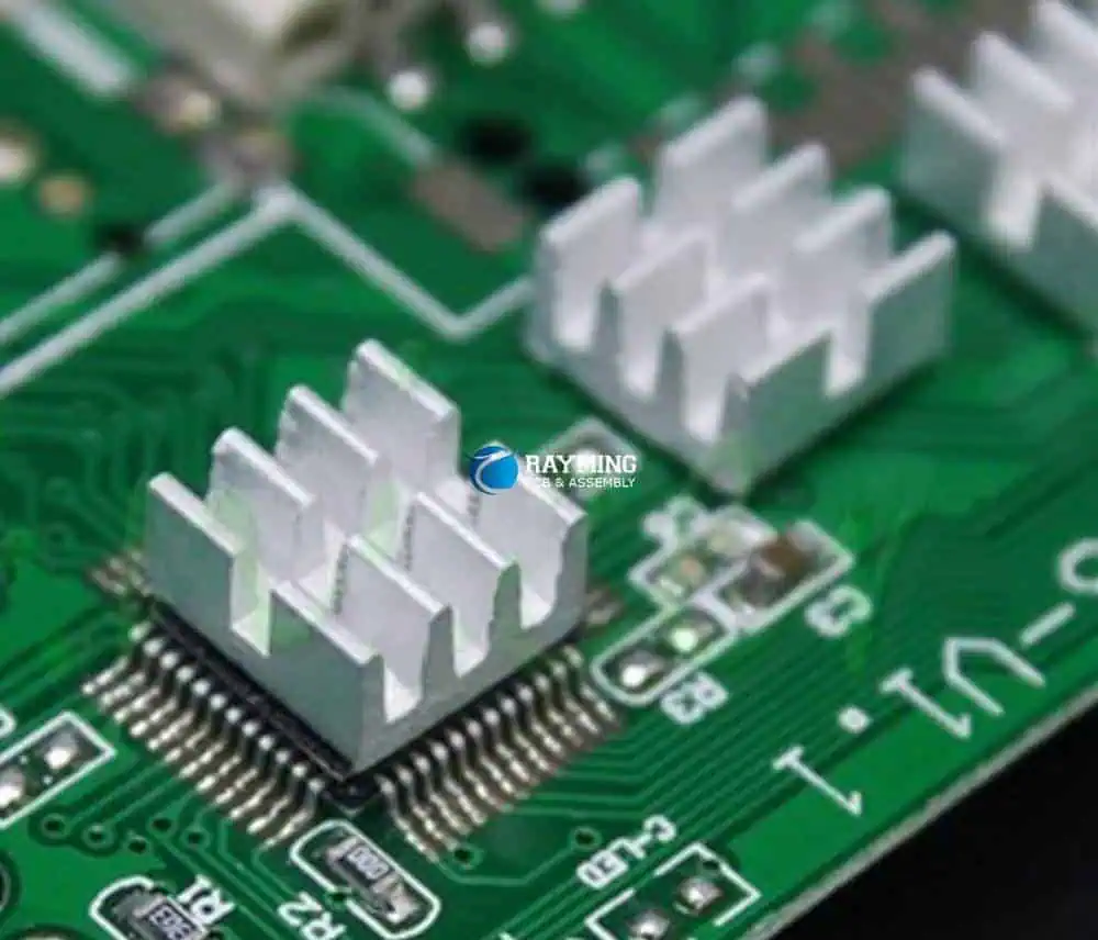
A heat sink comprises of a metal object, typically aluminum or copper, which is placed in contact with a heat generating component to conduct heat away and dissipate it into the ambient via fins exposed to airflow.

Key elements influencing heat sink performance include:

  • Base – Flat surface in contact with component to conduct heat from source
  • Fins – Ridges to increase surface area for more effective air convection cooling
  • Heat pipes – Closed channels containing liquid that evaporates and condenses, transmitting heat
  • Fans – Improve airflow across fins to expedite convection heat transfer
  • Thermal interface material – Grease/adhesive between sink and component to minimize thermal resistance

By efficiently sucking heat from a hot component and spreading it over a large area for air cooling, heat sinks enable reliable operation at higher powers.

Heat Sink Materials

Heat sink materials are selected for high thermal conductivity to optimize heat transfer from the heat generating component. Common materials include:

  • Aluminum – Offers excellent conductivity (200 W/mK) at low cost and weight. Most common sink material.
  • Copper – Very high conductivity (400 W/mK) but heavier and costlier than aluminum. Often used in high performance contexts.
  • Steel – Low cost but moderate conductivity (50 W/mK). Used when weight is not critical.
  • Silicon carbide – Lightweight with high conductivity (120 W/mK). Used in aerospace applications.
  • Diamond – Extremely high conductivity (2000 W/mK) but expensive. Used in specialized laser or semiconductor applications.
  • Ceramics – Insulating but can sustain high temperatures. Used as coating over metal cores.

Aluminum, copper and their alloys provide the best thermal performance for most electronics cooling applications.

Heat Sink Design Factors

Key aspects considered when designing an effective PCB heat sink include:

  • Thermal resistance – Should be low enough for required heat dissipation capacity. Depends on material and sink geometry.
  • Component power – Higher power components require greater heat flux capability.
  • Allowable temperature rise – Maximum permissible rise over ambient temperature.
  • ** Mounting method** – Conduction improved with thermal interface material and securing method.
  • Airflow – Natural or forced convection with fans impact heat transfer rate.
  • Size constraints – Physical dimensions may limit fin count and surface area.
  • Cost – Less expensive materials like aluminum often suffice for thermal needs.
  • Corrosion resistance – Sink materials should avoid corrosion over product lifetime.

Optimized heat sink design requires balancing these factors for effective thermal performance at reasonable cost.

Heat Sink Attachment Methods

Integrating heat sinks onto PCBs requires careful mounting provisions to minimize thermal resistance from component to heat sink:

Adhesives

  • Thermal adhesive physically attaches sink to component surface or package
  • Adhesive fills air gaps, improving thermal conduction
  • Silicone, epoxy or acrylic adhesive types available

Clips

  • Metal spring clips clamp sink securely onto component
  • Avoid applying excessive pressure to avoid damage
  • Clips allow sink detachment for component replacement/repair

Screws

  • Secure heat sink firmly to board or component using screws
  • Use insulation bushings/washers to prevent electrical shorts

Soldering

  • Reflowing solder paste permanently solders heat sink to lands around component
  • Provides robust thermal conduction path
  • Makes rework or repairs difficult

Adhesives, clips and screws allow some rework capability while soldering creates a permanent joint.

Thermal Interface Materials

Thermal interface materials (TIMs) are often inserted between the component and heat sink to minimize thermal resistance by filling microscopic air pockets that would otherwise hinder conduction:

  • Thermal greases – Silicone or ceramic pastes squeeze into surface irregularities. Require clamping pressure.
  • Thermal pads – Soft conductive sheets conform to surfaces. Some are dry applied, others use adhesive backings.
  • Phase change compounds – Wax-like materials melt during operation to fill gaps and voids.
  • Epoxy tapes – Adhere to surfaces and set to durable bond. Withstand scrubbing.

Applying the right amount ensures optimal conduction without air voids while avoiding excess amounts that increase resistance.

Heat Sink Fin Design

Fins provide the heat dissipating surfaces enabling convection cooling of heat sinks. Fin design parameters include:

  • Fin thickness – Thicker fins conduct heat better but add weight and material cost. Around 3mm is typical.
  • Fin height – Taller fins expose more surface area to airflow which increases heat dissipation.
  • Fin length – Longer fins increase exposed area but can be prone to bending/damage.
  • Fin density – Higher fin density boosts heat transfer but also increases air resistance. Around 5-10 fins per inch is common.
  • Fin shape – Rectangular or tapered fins affect airflow resistance and heat transfer characteristics.
  • Surface treatment – Textures, microstructures or coatings that increase surface area improve heat transfer.

Computer optimized fin shapes and patterns customized for the thermal profiles and airflow conditions enable maximum heat transfer.

Forced Convection Cooling

In forced convection, fans are mounted over heat sinks to dramatically improve airflow:

  • Axial fans – Most common. Direct air flow along length of fins.
  • Blowers – High pressure fans pushing air through dense fin arrays.
  • Centrifugal fans – Circulate air perpendicular to board expelling heat from enclosures.

Forced convection multiply heat transfer 5-10x compared to natural convection. The right fan needs to be matched to the impedance of the heat sink and airflow restrictions around board.

Heat Sink Modeling and Simulation

Heat sink designs are optimized using thermal modeling and computational fluid dynamics simulations. Important analysis parameters include:

  • Flow trajectories – Visualizes airflow patterns through heat sink for uniform distribution.
  • Pressure maps – Indicates high or low pressure zones causing flow resistance.
  • Air velocity – Quantifies airflow speed through fins ensuring sufficient ventilation.
  • Temperature mapping – Predicts localized heating across component, TIM and sink to identify hot spots.
  • Thermal gradients – Heat dissipation difference between base and fin tips should not exceed critical levels.

Such modeling ensures effective heat spreading from component to fins and no localized overheating, leading to optimal heat sink performance.

Heat Sink Applications

Heat sinks are ubiquitously used on PCB assemblies with high power dissipation components:

Power Supplies

  • Switching transistors and regulators
  • AC/DC rectifiers and converter ICs
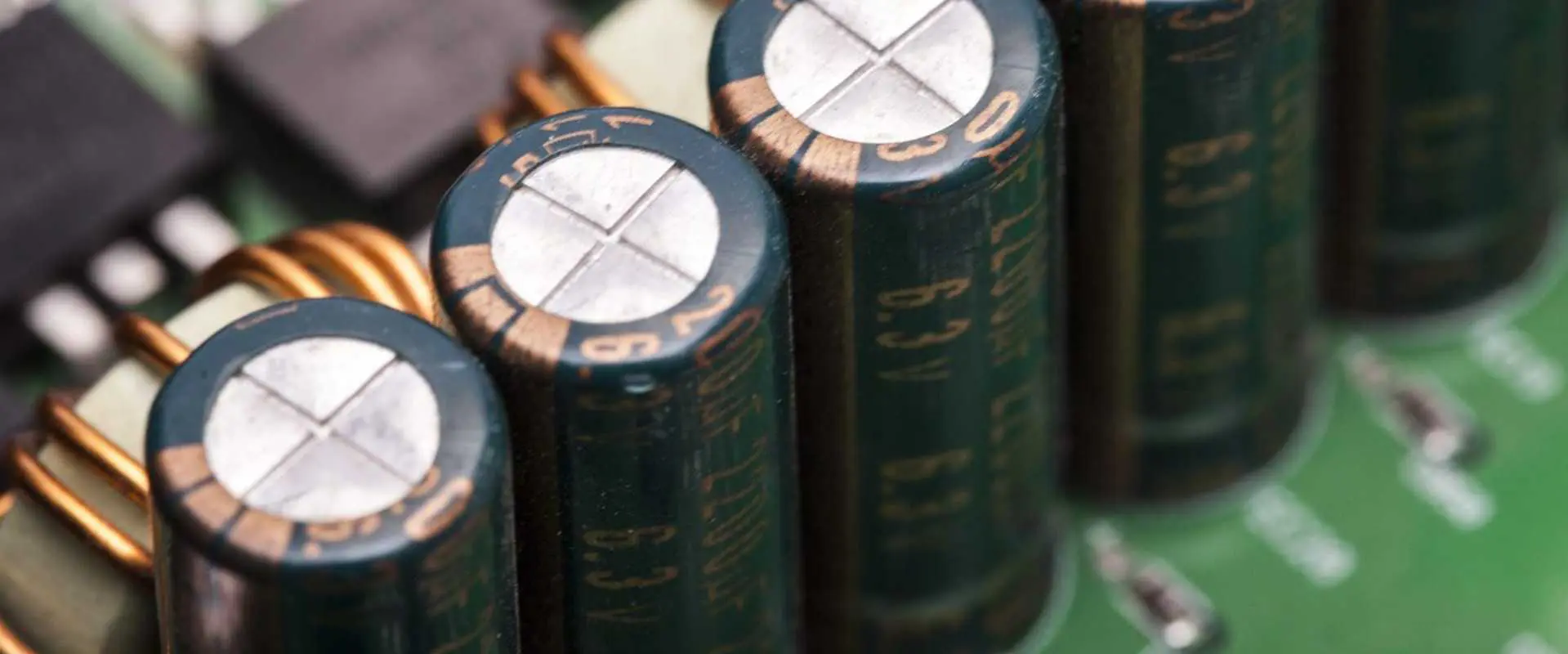
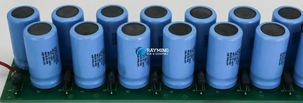
  • Bus capacitors

Motor Drives

  • IGBTs and power MOSFETs
  • DC/AC inverters
  • Braking resistors

Servers

LEDs

  • High brightness LEDs in lighting or displays
  • LED drivers

Audio Amplifiers

  • Output transistors
  • High wattage audio ICs

Industrial

  • PLC system controllers
  • Power monitoring equipment
  • Motor servo amplifiers

Any application needing to cool components dissipating over 1-2W can benefit from appropriately designed heat sinks.

Heat Sink Design Process

A typical workflow for designing an effective PCB heat sink involves:

  1. Determine maximum component power dissipation and ambient temperature.
  2. Estimate required heat sink thermal resistance from junction to ambient.
  3. Select candidate heat sink considering tradeoffs like performance, size and costs.
  4. Model heat sink in simulation software and optimize fin parameters.
  5. Simulate thermal performance under worst-case ambient temperatures and airflows.
  6. Verify adequate margin between model results and component temperature limits.
  7. Measure thermal performance on prototypes under real-world conditions.
  8. Iterate heat sink design as needed if measured results exceed thermal limits.
  9. Qualify final design across application operating conditions to ensure reliability.

Careful thermal design upfront prevents expensive redesigns and ensures equipment lifetimes and reliability goals are achieved.

Heat Sink Design Guidelines

Here are some best practice guidelines for developing effective heat sinks on PCBs:

  • Budget adequate clearance around heat sink for unrestricted airflow.
  • Orient heat sink to align with existing or forced airflows across the board.
  • Balance thermal dissipation needs with heat sink footprint constraints.
  • For ICs, maximize sink contact surface area overlid or exposed pad area.
  • Use thermally conductive interface materials to minimize contact resistance.
  • Secure heat sink firmly onto component using screws, clamps or soldering.
  • Verify heat sink isolation from any charged components to prevent shorts.
  • Monitor temperatures during testing to validate thermal design margins.
  • Consider adding redundancy with secondary heat sinks, thermal vias and ground planes.
  • Oversize slightly to account for degradation over product lifetime.

Conclusion

Heat sinks are an essential component enabling reliable operation of electronics required to dissipate substantial amounts of power. Their ability to efficiently conduct and spread heat using metallic materials with optimized fin geometries prevents device overheating.

With continually increasing power densities in modern PCBs driven by trends like wide bandgap semiconductors, wireless charging and high-speed ICs, effective thermal management using heat sinks, active cooling and thermal-aware design practices becomes mandatory.

The electronics industry will continue relying extensively on heat sink innovations spanning materials, 3D geometries, adaptive algorithms and computer simulations to sustain the relentless pace of advancement in energy efficient, high-performance electronic systems.

Frequently Asked Questions

Q: What is a heat sink in PCBs?

A: A heat sink is a metallic thermal management component like an aluminum plate that absorbs and dissipates heat from hot electronic components on a PCB through conduction and air convection.

Q: Why are heat sinks needed on PCBs?

A: Heat sinks prevent electronic components from overheating by efficiently conducting heat away and spreading it over fins exposed to airflow. This maintains safe device temperatures.

Q: What materials are used to make PCB heat sinks?

A: Aluminum and copper are most common due to high thermal conductivity. Other materials include steel, silicon carbide, diamond and ceramics.

Q: How are heat sinks attached to PCBs?

A: Common attachment methods include thermal adhesive, spring clips, screws and soldering. Thermal interface materials minimize contact resistance.

Q: How are heat sinks designed and simulated?

A: Important factors like airflows, fin parameters and thermal gradients are modeled using CAD and computational fluid dynamics simulation to optimize heat transfer.

Why Heat Sink PCBs are Important in Electronic Circuits

All electrical components in a circuit produce heat while the circuit is functioning. High-power devices such as power transistors, LEDs, and lasers produce heat. Some of these components can’t dissipate heat since they have a low dissipation capability.

Heat build-up in the component can result in total failure or premature failure in the device. Therefore, heat sink boards are a perfect way to conquer these problems. These circuit boards are used in most applications because of their cooling functions. PCB manufacturers include a heat sink in PCB due to the numerous benefits it offers.

Passive Heat Exchange

Heat sink PCBs feature a large surface area that cools off. These boards act as passive heat exchangers. The component of a device that canโ€™t control its temperature needs heat sink PCBs. To improve performance, every heat in a component of an electronic circuit must be dissipated. This will help to prevent the component from experiencing any failure.

Maintains Thermal Stability

Heat sinks in PCB help to maintain thermal stability in any electronic device. Thermal stability is very important for electronic components of any circuit. Heat sink PCBs can survive in any temperature because of their cooling ability. This is a major reason these PCBs are employed in high-performance applications.

Heat sinks donโ€™t only dissipate heat; they also provide heat during low temperatures. They do this by generating thermal energy for the smooth functioning of the circuit.

Spreads heat

Heat sinks serve as heat spreaders in some applications. For instance, a heat sink PCB functions as covers on the memory of a computer. Heat sinks also help to cool off the graphic processors and CPU of computers.

Prevents system failure

Heat sinks prevent system failure in a circuit. The absence of a heat sink can cause the failure of components. It is advisable to implement a heat sink in a PCB to prevent overheating. Component failure is one of the common problems of electronics or electrical devices.

Different types of mechanical and electronic devices generate heat which heat sinks absorb. Heat sink PCBs play significant roles in mechanical, electronic, nuclear, and solar processes.

Types of Heat Sink

Heat sinks are available in various types. Each of these types has its function. However, they share some common characteristics or features. Heat sinks are mostly made from metal like aluminum or copper. The commonest designs for a heat sink are the fin layout. Some versions utilize stamping and pins to increase the surface area and heat transfer rate.

Passive heat sink

A passive heat sink doesnโ€™t feature additional products while cooling a component. It isnโ€™t assisted by additional processes. These heat sinks donโ€™t have any mechanical components. They dissipate heat through the convection process. When you use this heat sink on PCB, it gives reliable results.  Experts recommend that engineers should maintain the flow of air across the fins of this heat sink.

Passive heat sinks serve as a standalone solution since they donโ€™t use other cooling methods. These heat sinks are bigger than active heat sinks. Passive heat sinks disperse absorbed heat via the direct contact between them.

Active heat sink

This type of heat sink uses additional products to enhance its cooling capacity. Active heat sinks use powered processes like water pumps and fans. These processes or products help to increase the heat transfer rate. In some electronic systems, these coolers run off the internal power supply. This type of heat sink isnโ€™t ideal for long-term applications. This is because it has moving parts.

Active heat sinks make use of one or more fans. These fans are either above or on the side of the fin stack. Some advanced active heat sinks use water to transfer heat from a source.

Types of Heat Sink Based on Material

Aluminum heat sink

An aluminum heat sink is a less expensive choice for heat sinks. This type of heat sink is designed in a way that the generated heat escapes via some thin metal fins. Aluminum is the commonest material used in heat sinks. The thermal conductivity of aluminum is different from copper. The thermal conductivity of the metal affects the heat sinkโ€™s heat transferring capacity.

Copper heat sink

Most heat sinks are made of copper. Copper is a good thermal conductor and has got great heat transfer capabilities. This type of heat sink draws away heat from the device you want to cool. Heat sink PCB made of copper is more expensive.  Most PCB heatsink designs use copper.

Pinned heat sink

A pinned heat sink is an alternative design fin heat sink. The core block of the pinned heat sinks features a cluster of rods or pins that extends outward or upward. This type of heat sink has a better overall surface. But, they donโ€™t offer good performance improvement in most applications.

Finned heat sink

This type of heat sink is designed from a block of metal. This metal is available in a large number of thin plates that extend away from the central block. Finned heat sink features a better surface area. This makes it more effective in transferring heat away from the component. The manufacturing and designing of this heat sink involve either die-cast or forged models.

Heat Sink Types Based on Manufacturing Techniques

Circuit board heat sink

Various manufacturing methods are used in manufacturing heat sinks.

Stamped heat sink

This type of heat sink features stamped metals. These metals can form a certain shape. The stamp designs the heat sinks anytime metal moves via the stamping machine. Stamped heat sinks are ideal for low-power applications.

Bonded heat sink

This type of heat sink is ideal for large applications that demand sensible performance. Bonded heat sinks are designed by combining separate fins of metal to the heat sinkโ€™s base. There are two different methods for doing this. They are the brazing and the thermal epoxy methods.

Skived heat sink

Skived heat sinks employ skiving for their manufacturing. Skiving is the use of fine blocks of metals for manufacturing heat sinks. Skived heat sinks can be high or medium-performing heat sinks.

Swaged heat sink

Swaged heat sinks are medium-performing heat sinks. Swaging is a manufacturing technique that involves a cold working forging process. However, it can undergo a hot working process.

Forged heat sink

Forging involves utilizing compressive forces. This technique is used for manufacturing aluminum and copper heat sinks.

Machining heat sink

This type of heat sink uses a machining process for its manufacturing. Gangsaw helps to eliminate a block of material. This type of manufacturing process is expensive since a lot of metal may waste.

Applications of Heat Sink PCB

Heat sink PCBs are used in several applications due to the functions they perform. These circuit boards are ideal for high-performance applications. They are also suitable for use in devices that produce a high amount of heat.

LEDs

Heat sink PCBs are commonly used in Light-emitting diodes (LED). These PCBs provide effective cooling for LED pcb. Heat sink circuit boards prevent excess heat from damaging LEDs. Most high-power LEDs feature heat sink PCBs.

Computers

Heat sink PCBs are a common component of computers. The CPU of computers needs a heat sink. Electrical activity in the CPU produces a good amount of heat. This may cause damage to the chipset. A heat sink helps to offer a good path for heat to pass through. The CPU comes with a heat sink. Some manufacturers use a particular type of heat sink for their CPUs.

Industrial facilities

Most industrial devices generate heat while in use. Therefore, a heat sink PCB is ideal for use in industrial equipment. Heat sinks are connected on a circuit board because of their cooling properties. They reduce the amount of absorbed heat in a mechanical device while running.

Soldering

During the soldering process, heat sinks help to protect electronic components. Some components need the protection of a heat sink during soldering.

Consumer products

Heat sink PCBs are used in most consumer products. Some electronic devices in the home come with heat sinks. This is because some components of these devices generate a lot of heat. Therefore, heat sink PCBs help to dissipate heat in these devices.

The Limitations of Heat Sink PCB

FULL PCB MANUFACTURING Quote

The cooling of electronic devices is important for their long-lasting function. The need for circuit bard cooling has continued to increase. Heat Sink PCBs help to dissipate heat in electronic devices. The importance of the use of heat sinks in PCBs canโ€™t be overemphasized.

There are different types of heat sink PCB with different thermal resistance values. These PCBs ensure cooling.  Heat sink PCBs have their challenges. One of the major challenges is the joining of the circuit board with the heat sink.

Another challenge is the aerial use of thermal adhesive without air pockets between the components.  The properties of the thermal adhesive caused this problem. However, thermal engineers achieved good distribution by using pressure pins. The vacuum joining process presents a reliable result.

The dissipation of heat loss from chips is a major issue for developers. There are several ways to link a heat sink to the source of the heat. The fabrication of a heat sink PCB involves creating a separate metal heat sink. Then, manufacturers use liquid adhesive to attach this heat sink to a finished board.

Heat Sink Dissipation Method

Heat sink PCBs use some methods to dissipate heat which are:

  • Heat transfer compounds
  • Metal heat-conducting plate
  • Higher copper thickness
  • Metal core

Heat transfer compounds

For heat sink PCBs, fabricators use a screen-printing procedure to apply the heat transfer compound to the silkscreen. The layer’s thickness ranges between 100 โ€“ 150 ฮผm.

Metal core

Rather than using the standard base material, a copper or aluminum sheet is used here.  A prepreg is used to laminate a copper foil onto a metal core.

Higher copper thicknesses

When it comes to thick-copper boards, the copper absorbs the heat and directly dissipates it. The copper thicknesses are 400 ฮผm, 210 ฮผm, and 105 ฮผm. This method involves high-cost production since the conductor structure requires much effort.

Metal heat-conducting plate

In this method, a heat sink PCB goes through the standard production process. Manufacturers use a prepreg to press mold the PCB to the metal heat-conducting plate.

Factors to Consider in Heat Sink Design

The design of a PCB is a very complex process. The importance of heat sinks in PCB canโ€™t be overstressed. Engineers need to consider some factors when implementing a heat sink on PCB. Heat sinks transmit thermal energy from electronic components into a cooling medium.

Several factors determine the performance of heat sinks. The materialโ€™s thermal conductivity and attachment method are some of these factors. Engineers can determine the parameters of a heat sink via analysis and modeling.

Heat sink materials

Alloys, aluminum, and copper are materials used for designing heat sinks. Copper is a good thermal conductor that resists corrosion and absorbs heat. This material is ideal for heat sinks due to its properties. However, it is a more expensive option.

Diamond is another ideal material for thermal applications. This is because it features lattice vibrations. Another alternative is the bonding of aluminum and copper. In this case, aluminum is the dominant material due to its lightweight. This is a perfect combination for heat sinks in computers.

Heat sink fins

Heat sinks feature fins in their design. These fins offer the necessary surface area for heat dissipation. They cool the heat source. The finโ€™s efficiency determines the performance of the heat sink. Once there is a flow of heat through the fin the temperature reduces from the base.

The arrangement and location of the fins also affect the performance of the heat sink. The design and shape of the fins will greatly determine the heat sinkโ€™s performance.

Thermal resistance

Thermal resistance determines how heat sinks perform. This factor determines heat flow. In order to achieve an efficient heat sink, the thermal management system needs to be combined with a cost-effective design.

Attachment methods

There are different methods of attaching heat sinks to the component of a device. Using the appropriate method helps to enhance the heat sinkโ€™s thermal performance. Thermal tape, standoff spacers, epoxy, and flat spring clips are examples of attachment methods.

Characteristics of a Good Heat Sink

A good heat sink features some characteristics that make them ideal in most applications. The characteristics of this heat sink are;

  • Heat dissipation correlates with the temperature difference between the ambient temperature and the device.
  • The mounting method is very critical. It uses screws rather than utilizing glue, clips, or sticky tape.
  • Heat dissipation correlates with the finsโ€™ surface area. Therefore, it should have a very large surface.
  • Flat surface must have contact with the source of heat. This is very important as it allows a layer of thermal compound to minimize thermal resistance between the devices.
  • Heat sink design must enable free flow of air through the fins.

PCB Heat Dissipation Techniques

As PCBs are a core aspect of electronic devices, heat dissipation techniques are very important. Most electronic devices produce heat while they are running. Heat sink PCB helps to spread heat across components in a circuit. Below are some heat dissipation techniques;

Use cooling fans and heat sinks

If a printed circuit board generates a high amount of heat. You will have to incorporate fans and heat sinks in the design. Manufacturers attach heat sinks to components that produce the most heat. Power transistors, CPUs, and voltage regulators are such components. Here, the heat sinks are on the PCB. You can also install a cooling fan to help discharge the hot air in the environment.

Thermal via arrays

You can make use of thermal via arrays to transform a PCB into an onboard heat sink. The idea behind this is for flow of heat from the components to the copper area. Then the heat dissipates via the air from the vias.

Thermal via array must feature a large diameter to allow effective dissipation of heat. The vias must feature padded holes that connect to the copper area. More thermal vias also help dissipation of heat.

Use wider traces

Ensure you increase the traceโ€™s width to improve heat dissipation to the air. This will help to reduce the traceโ€™s thermal resistance and also minimize heat spots. Good copper trace thickness can offer a low impedance path.

These heat dissipation techniques are very important in electronics. Heat sinks play a significant role in the dissipation of heat in electronic devices. Components like power transistors and microcontrollers often generate heat. This happens especially when the load current rises.

Frequently Asked Questions

How do you calculate heat sink performance?

The performance of heat sinks is also known as thermal resistance. It is measured in ยฐC/W. If a heat sink has a thermal load of 50W and the heat source rises by 20 ยฐC. One can say the heat sink rating is 20/50 ยฐC/W. This is equal to 0.40 ยฐC/W.

How can the impact of heat on PCBs be minimized?

To do this, separate heat-sensitive components and heat-generating ones on the PCB. This can help you concentrate heat dissipation to a certain area. Doing this will also prevent the heat from going towards the heat-sensitive components. Place heat-producing components on the top when mounting the PCB vertically. You can reduce the heat dissipation path by placing the components towards the PCBโ€™s edge.

What is a thermal simulation in PCB?

Thermal simulation locates the temperature of a thermal hotspot in a printed circuit board. Locating the thermal hotspots help to prevent the risk of failure in devices.

Conclusion

Electronic components can operate within a definite temperature range. When the temperature around these components rises beyond the upper limit, there can be a breakdown. Excessive heat can have a negative effect on the performance of the component.

For instance, MCU uses more energy at high temperatures. The lifespan of an electronic device will reduce if it is exposed to too much heat.  Too much heat can lead to premature failure of components. Therefore a heat sink PCB is an ideal choice for most electronics.

What Is Xilinx XC7A35T-2FGG484i?

Xilinx XC7A35T-2FGG484i

The Xilinx XC7A35T-2FGG484i device belongs to the low-cost, low-power Artix-7 family of FPGAs built on 28nm high-performance, low-power (HPL) process technology. With 33K logic cells, 125MHz DSP slices and 12.5Gbps transceivers, the XC7A35T provides an optimized blend of programmable logic, real-time processing, high-speed I/O and power efficiency ideal for applications including motor control, functional safety, video bridging, software defined radio, broadcast camera links and ultrasound equipment.

This article provides a technical overview of the XC7A35T architecture, available resources, target applications, design flow and benefits for system designers.

XC7A35T-2FGG484i Overview

The Xilinx XC7A35T belongs to the Artix-7 family which spans small to large capacity FPGAs and SoCs supporting space constrained embedded applications. Key attributes include:

  • 33K logic cells based on look-up tables (LUTs) as the basic logic building block
  • 125MHz DSP slices with 25 x 18 multipliers
  • 12 dual-channel gigabit transceivers operating up to 12.5Gbps
  • 258 maximum user I/Os
  • High speed memory interface supporting DDR3 at up to 1600Mbps
  • Configurable mixed-voltage I/O banks
  • High performance, low power 28HPL process

The 2FGG484 package designates a compact 17×17 mm 484-ball flip-chip grid array with 1.0mm ball pitch. It provides ample connectivity for embedding the Artix-7 in space constrained embedded systems.

XC7A35T Internal Architecture

The Artix-7 family architecture balances high density programmable logic fabric along with frequently needed hardened blocks for embedded systems.

Programmable Logic Fabric

The core programmable logic is built from slices containing LUTs, flip-flops, multiplexers, arithmetic and wide function generators. Key attributes:

  • 6-input LUTs efficiently implement logic functions using only a single LUT per slice
  • Flip-flops for sequential logic – register, shift register or latch operation
  • Carry logic for arithmetic functions
  • Block RAM for distributed memory storage

DSP Slices

The 125 embedded 18×25 multipliers and 48-bit accumulators enable high-performance arithmetic processing.

Block RAM

1.9Mb of distributed 36Kb block RAM provides on-chip data storage with built-in FIFO support.

Transceivers

Up to 12 multirate transceivers operating at up to 12.5Gbps support high-speed serial I/O connectivity.

PCI Express

Two integrated Gen2 PCIe blocks enable direct chip-to-chip communication.

Multi-Standard I/Os

The configurable I/O blocks allow matching electrical interfaces to a wide range of standards including LVDS, HSTL and SSTL.

XC7A35T Target Applications

The XC7A35T is designed to meet the needs of compute-intensive, connectivity-centric embedded systems across industrial, automotive, communications, aerospace/defense and functional safety applications:

Industrial Automation

  • Motor drives
  • Inverters
  • PLC systems
  • Process control
  • Machine vision

Automotive

  • Camera links
  • RADAR/LiDAR processing
  • Driver assistance systems
  • Functional safety

Wireless Infrastructure

  • FMCW radar modems
  • Microwave radio links
  • Small cell baseband processing
  • Optical network cards

Aerospace and Defense

  • RADAR and sonar processing
  • Communications monitoring
  • Video tracking systems
  • Encryption/decryption

Test and Measurement

  • Protocol analyzers
  • Video test signal generators
  • High-precision metrology

The cost-optimized programmable logic balanced with integrated processing enables these demanding applications.

XC7A35T-2FGG484i Benefits for Designers

The XC7A35T architecture and capabilities provide hardware engineers with several advantages:

High Performance

  • 33K logic cells enables implementation of complex digital logic
  • 125MHz DSP slices accelerate math-intensive algorithms
  • 12.5Gbps serial connectivity to transfer high-speed data

Power Efficiency

  • 28nm process enables low static and dynamic power consumption
  • Integrated blocks reduce external components lowering overall system power

Functional Safety

  • Configuration CRCs and error detection circuitry improve reliability

Scalability

  • Multiple density, I/O and transceiver options within Artix-7 family

Cost

  • Mature 28nm process combined with optimized architecture provides low cost

For demanding connectivity-centric embedded systems, the XC7A35T delivers high throughput signal processing coupled with flexible programmable logic at very compelling price points.

XC7A35T Design Flow

Xilinx provides powerful design tools for programming the XC7A35T FPGA:

  • Vivado Design Suite – Enables system design, logic synthesis, placement and routing
  • Vivado IP Integrator – Connects intellectual property blocks into integrated designs
  • SDSoC Development Environment – Supports C/C++ embedded software design
  • Vivado HLS – Converts C/C++ code into tuned logic implementations
  • System Generator – Implements high-performance DSP designs
  • ChipScope Pro – Provides low-level debug capability

The typical design flow involves:

  1. Create register transfer level (RTL) code defining desired functionality
  2. Run RTL simulations to verify correct behavior
  3. Synthesize RTL into Xilinx primitives using Vivado synthesis
  4. Place and route design to map into XC7A35T physical resources
  5. Generate bitstream representing complete FPGA configuration
  6. Program finished bitstream into XC7A35T device
  7. Validate operation and timing in real system

XC7A35T vs. Larger FPGAs

Xilinx Chips
Xilinx Chips

It is useful to contrast the XC7A35T against higher density FPGAs like the Kintex-7:

Programmable Logic

  • XC7A35T offers 33K logic cells using 6-input LUTs
  • Kintex-7 provides up to 474K logic cells using 6-input LUTs

Transceivers

  • Both support up to 16 transceivers operating at 12.5Gbps

Memory Interfaces

  • Both support external DDR3 memory interfaces up to 1600Mbps

DSP Slices

  • XC7A35T – 220 DSP slices operating at 125MHz
  • Kintex-7 – Up to 3600 DSP slices at 500MHz+

Cost

  • XC7A35T optimized for low cost high volume applications
  • Kintex-7 costs approximately 40% higher

For applications where power efficiency and unit costs are critical, the XC7A35T offers the ideal programmable logic solution. When maximum performance is mandatory, Kintex-7 provides superior DSP and memory interfacing capabilities.

Conclusion

By integrating abundant I/Os, DSP slices, serial transceivers, block RAM, and PCIe blocks together with cost-optimized programmable logic fabric, the Xilinx XC7A35T-2FGG484i provides an extremely capable chip foundation for next-generation industrial controls, motor drives, functional safety systems, communications infrastructure, test instrumentation and aerospace/defense electronics.

For embedded systems engineers challenged with staying competitive on performance, capabilities, power efficiency and unit costs, the Artix-7 family offers an invaluable platform for accelerating innovation and progress from concept to deployed solution.

Frequently Asked Questions

Q: What is the Xilinx XC7A35T FPGA?

A: It is a low-cost, low-power Artix-7 series FPGA with 33K logic cells, 125MHz DSP blocks and 12.5Gbps transceivers built on a 28nm fabrication process.

Q: What are some key components of the XC7A35T architecture?

A: This includes programmable logic fabric using 6-input LUTs, 220 DSP slices, 1.9Mb of block RAM, up to 16 transceivers, PCIe blocks, and configurable mixed-voltage I/O.

Q: What kinds of applications can the XC7A35T FPGA address?

A: Target applications span industrial automation, motor drives, functional safety systems, wireless infrastructure, broadcast video, test instrumentation.

Q: How does the XC7A35T compare against larger FPGAs like Kintex-7?

A: Kintex-7 offers approximately 40% higher logic capacity and performance but at a greater cost. XC7A35T optimizes cost and power efficiency.

Q: What design tools support programming XC7A35T FPGAs?

A: Xilinx’s Vivado Design Suite supports the end-to-end flow from RTL design entry to layout and implementation culminating in bitstream generation.

What Is Xilinx XC6SLX45T-2FGG484i ?

Xilinx XC6SLX45T-2FGG484i

The Xilinx XC6SLX45T-2FGG484i is a mid-range capacity Spartan-6 series field programmable gate array (FPGA) fabricated using a low-power 45nm process. This particular device provides a balance of programmable logic resources, abundant I/Os and hardened functional blocks ideal for applications including industrial networking, motor control, video processing, software defined radio and functional safety systems.

This article covers the XC6SLX45T architecture, available resources, target applications, design considerations and benefits for electronics engineers.

XC6SLX45T-2FGG484i Overview

The Xilinx XC6SLX45T belongs to the Spartan-6 FPGA family built on a 45nm node manufacturing process. Key attributes include:

  • 45K logic cells featuring 6-input LUTs as the basic logic building block
  • 216 DSP slices optimized for arithmetic and signal processing tasks
  • 12.2Mb of distributed block RAM for on-chip data storage
  • 6.6Gbps serial transceivers for high-speed chip-to-chip communication
  • 500+ user I/Os supporting dozens of electrical interfaces
  • Advanced power management techniques for low static and dynamic power
  • Industrial temperature rating of -40ยฐC to +100ยฐC

This combination of programmable logic, hardened blocks and I/O enables implementation of complex digital systems with high throughput capabilities.

The 2FGG484 package designates a 23x23mm 1.0mm pitch 484-ball fine-pitch BGA with 7.5mm ball height. This compact form factor provides adequate I/Os for most applications in a small surface mount package.

XC6SLX45T FPGA Internal Architecture

The Spartan-6 architecture is optimized to deliver balanced programmable logic capabilities together with essential integrated peripherals useful across many applications.

Configurable Logic Blocks

The core programmable logic fabric is built from Configurable Logic Blocks (CLBs). Each CLB includes:

  • 2 Slices, each with 4 6-input LUTs and 8 flip-flops
  • Arithmetic carry logic
  • Distributed RAM for local storage

CLBs are interconnected by a flexible routing fabric enabling complex digital logic implementation.

DSP Slices

216 dedicated 18×18 multipliers and 48-bit accumulators accelerate math-intensive functions like filters, FFTs and video processing.

Block RAM

12.2Mb of distributed 36Kb block RAM provides on-chip data storage. Built-in FIFO support, byte write enable and ECC mode simplifies memory management.

Clock Management

Digital Clock Managers (DCMs) and Mixed Mode Clock Managers (MMCMs) provide self-calibrating, fully digital solutions for distributing and manipulating clocks across the device.

I/O Blocks

Configurable I/O blocks around the periphery of the FPGA enable interfacing to a wide range of electrical standards including LVTTL, LVCMOS, LVDS and SSTL. Maximum I/O speed reaches 1.6Gbps.

Transceivers

Integrated serial transceivers operate at up to 6.6Gbps supporting protocols like PCIe, Gigabit Ethernet, CPRI and Serial RapidIO.

XC6SLX45T Target Applications

The XC6SLX45T provides an ideal blend of capabilities for connectivity-oriented embedded applications including:

Industrial Networking and Motor Control

  • EtherCAT slaves
  • Functional safety systems
  • Servo motor control
  • Human machine interface (HMI)
  • SCADA systems

Wireless Communications

  • 4G LTE radio control
  • Small cell baseband processing
  • Software defined radio
  • Microwave radio links

Broadcast Video

  • Video overlays
  • Format conversion
  • Frame synchronization
  • Distribution amplifiers

Medical and Scientific

  • DNA sequencing
  • Particle detection
  • Weather monitoring
  • Ultrasound and MRI processing

Aerospace and Defense

  • RADAR signal processing
  • Mission control
  • Navigation algorithms
  • Encryption/decryption

The XC6SLX45T balances performance, power and costs for connectivity-centric applications requiring reasonable logic capacity.

XC6SLX45T-2FGG484i Benefits for Designers

Xilinx FPGA distributor

For hardware engineers, the XC6SLX45T-2FGG484i provides several compelling advantages:

Performance

  • 45K logic cells enables complex digital system implementation
  • DSP slices accelerate math-intensive algorithms
  • 6.6Gbps transceivers allow high-throughput serial I/O

Low Power

  • 45nm fabrication optimized for low static and dynamic power
  • Suspend mode reduces power consumption to just 11mW

Reduced BOM

  • 12Mb RAM and DSP blocks minimize external memories and processors
  • Transceivers eliminate external SERDES ICs

Design Security

  • Bitstream encryption secures compiled designs from copying

Reliability

  • Industrial -40ยฐC to +100ยฐC temperature rating

While balancing cost, the XC6SLX45T provides ample functionality for applications at the intersection of programmable logic, real-time processing and high-speed interfacing.

Design Tools and Methodology

Xilinx offers a mature tool flow for programming the XC6SLX45T FPGA:

  • ISE Design Suite – enables design at register-transfer level (RTL) using Verilog or VHDL
  • Embedded Development Kit (EDK) – creates hardware/software systems using the Microblaze soft core CPU
  • ChipScope Pro – provides debug capability with real-time signal visualization
  • iMPACT – programs bitstream files into the FPGA through common interfaces

Typical design steps include:

  1. Create register-transfer level (RTL) code to define desired functionality
  2. Run RTL simulations to verify correct behavior
  3. Synthesize RTL into Xilinx primitives using ISE tools
  4. Verify timing, power and utilization meet requirements
  5. Generate bitstream file representing complete FPGA configuration
  6. Program finished bitstream into the XC6SLX45T-2FGG484i FPGA

XC6SLX45T vs. Larger FPGAs

It is useful to contrast the XC6SLX45T against larger capacity FPGAs like Xilinx’s Virtex-6:

Programmable Logic

  • XC6SLX45T provides 45K logic cells using 6-input LUTs
  • Virtex-6 offers up to 360K logic cells using 6-input LUTs

Transceivers

  • XC6SLX45T – 6.6Gbps data rate, up to 16 channels
  • Virtex-6 – Up to 11.2Gbps, 96 channels

Memory

  • Both support similar 36Kb block RAM capacities
  • Virtex-6 adds 512Mb – 1Gb dedicated DDR3 memory interfacing

DSP Slices

  • XC6SLX45T – 216 slices @ 25 x 18 multipliers
  • Virtex-6 – Up to 2016 slices @ 25 x 18 multipliers

Cost

  • XC6SLX45T optimized for low cost by removing top-tier features
  • Virtex-6 costs approximately 4-5X higher

For applications with intelligence distributed across multiple nodes, XC6SLX45T provides the optimal blend of capability and affordability.

Conclusion

The Xilinx XC6SLX45T-2FGG484i hits the sweet spot between programmable logic density, real-time processing capability and high-speed interfacing required in industrial controls, motor drives, communications infrastructure and functional safety systems.

Built on a low-power 45nm process, the XC6SLX45T balances logic capacity, abundant I/Os, DSP blocks and serial transceivers in a compact surface mount package – making it an extremely versatile chip for connectivity-centric applications demanding reasonable performance.

Frequently Asked Questions

Q: What is the Xilinx XC6SLX45T FPGA?

A: It is a low-cost Spartan-6 series FPGA with 45K logic cells, DSP slices and 6.6Gbps transceivers, built on a 45nm fabrication process.

Q: What are the key elements in XC6SLX45T architecture?

A: This includes 45K logic cells using 6-input LUTs, 216 DSP slices, 12Mb of block RAM, MMCM clock management, and up to 16 serial transceivers.

Q: What design tools can be used for programming XC6SLX45T FPGAs?

A: Xilinx offers the ISE Design Suite for RTL design entry, ChipScope Pro for debug, and iMPACT for final bitstream programming.

Q: What are some common applications for the XC6SLX45T FPGA?

A: Target applications include industrial motor control, functional safety systems, wireless infrastructure, broadcast video, aerospace electronics.

Q: How does XC6SLX45T compare to larger FPGAs like Virtex-6?

A: Virtex-6 offers 4-5X higher logic capacity and transceiver count but costs substantially more. XC6SLX45T provides an optimized cost/capability blend.

What is a Printed Circuit Board ( PCB )?

military rogers pcb board

What is a Printed Circuit Board?

A Printed Circuit Board (PCB) is the foundation of modern electronics, serving as both an electrical connector and a mechanical support for electronic components. Here’s what you need to know:

  1. Structure:
    • PCBs consist of alternating layers of conductive copper and insulating material.
    • Conductive features include copper traces, pads, and planes.
    • Insulating layers provide mechanical structure and electrical isolation.
  2. Surface Finish:
    • A non-conductive solder mask covers the board for protection.
    • Silk-screened legends guide component placement.
  3. Manufacturing Process:
    • Inner copper layers are etched to form circuit patterns.
    • Multiple layers are laminated together to create the full stack-up.
    • The bare board is then ready for component assembly.
  4. Assembly:
    • Electronic components are soldered onto the board.
    • The completed assembly is called a PCBA (Printed Circuit Board Assembly).
  5. Purpose:
    • Creates electrical connections between components.
    • Provides mechanical support for components within a device.

PCBs are essential in creating compact, reliable electronic devices across various industries, from consumer electronics to aerospace technology.

Read more about PCB technical:

6 Layer ENIG PCB
Flex PCB
Rigid Flex PCB
Rogers PCB
Antenna PCB
HDI PCB

Types of PCBs

While rigid PCBs are the most common, there are various types of circuit boards constructed on different materials. Here’s an overview of the main PCB types:

  1. Single-sided: Components on one surface, typically with a copper ground plane on the back.
  2. Double-sided: Components on both surfaces, with each surface acting as a signal layer.
  3. Multi-layer: Internal conductive layers for signals or planes. Can be single or double-sided.
  4. Rigid-flex: Combines rigid sections with flexible polyimide ribbons, allowing for movable elements.
  5. Flex PCBs: Entirely flexible, made of polyimide ribbons. Can have mounted components like rigid PCBs.
  6. Printed flex PCBs: Flexible base with printed copper conductors, similar to flex PCBs.
  7. Metal-core PCBs: Use a metal core (usually aluminum) for improved rigidity and heat dissipation.
  8. Ceramic PCBs: Used in applications requiring high thermal conductivity.
  9. HDI PCBs: High-density interconnect boards for very high pin count components.
  10. UHDI and Substrate-like PCBs: Extremely small and dense, requiring specialized additive manufacturing processes.

Each type has unique fabrication and assembly processes. Modern ECAD software can assist in designing any of these PCB types, provided the correct design rules are applied.

PCB Manufacturing Process Overview

Strip film etching line

PCBs are fabricated using sophisticated processes optimized for high yield and reliability across large panel sizes containing multiple boards:

  • 1. Design – The PCB layout is designed in CAD software based on circuit requirements and component footprints.
  • 2. Fabrication – Blank copper-clad laminate sheets are drilled, plated and coated with photoresist. An imaging process transfers the PCB layout onto the panel.
  • 3. Etching – Exposed copper is etched away chemically, leaving only the protected circuit traces/pads. Photoresist is then stripped.
  • 4. Plating – Conductive barrel walls are plated in drilled holes to create plated through hole (PTH) interconnections.
  • 5. Solder mask – Epoxy layers are applied for insulating exposed copper traces from solder and environmental corrosion.
  • 6. Silkscreen – Paint masks are used to apply component identifiers and outlines for assembly.
  • 7. Testing – Manufacturing defects are detected using electrical test and imaging processes.
  • 8. Panelization – Individual PCBs are depanelized from the larger sheets into stand-alone boards.
  • 9. Population – Electronic components are soldered onto the boards using surface mount (SMT) and/or through-hole technologies.

These steps produce finished printed circuit boards ready for integration into electronic products and systems.

PCB Substrate Materials

The PCB substrate, also referred to as laminate, forms the base layer upon which the copper traces are fabricated. Key laminate requirements include:

  • Electrical insulation to prevent shorting between traces
  • Thermal conductivity to dissipate heat from components
  • Structural rigidity for mechanical support
  • Dimensional stability across temperature and humidity
  • Process compatibility for fabrication and assembly

Popular PCB substrate materials include:

  • FR-4 – Woven fiberglass cloth in an epoxy resin binder. Low cost, globally available.
  • CEM-1/3 – Cotton paper base material. Cost effective, suitable for low frequencies.
  • PTFE – Synthetic fluoropolymer offering highest performance but costly.
  • Polyimide – Withstands very high temperatures. Used in flex circuits.
  • Alumina – Ceramic-based; very rigid and thermally conductive for high power PCBs.
  • Metal core – Base metal layer for max heat dissipation.

The substrate choice affects PCB performance parameters, fabrication methods and ultimate application suitability.

Conductive Layers

The conducting layers provide the electrical connectivity in a PCB by etching the laminated copper foils into desired circuit patterns. Key considerations include:

  • Copper thickness – Varies from 0.5 oz (0.0007 inches) to 6 oz (0.0042 inches) or more based on current needs.
  • Foil type – Rolled copper has better flexibility but lower current capacity than electrodeposited copper.
  • Layer count – Number of conductive layers laminated determines circuit complexity. Modern PCBs can have over 30 conductive layers.
  • Layer stackup – Stacking order of power, ground and signal layers optimized for electrical performance.
  • Trace dimensions – Conductor width, spacing and thickness dictated by current, voltages and insulation needs.
  • Trace profile – Rectangular or trapezoidal cross-section optimized for production yields.

Proper layer stackup design and copper weight/density minimizes noise coupling and enables routing high speed signals across the PCB.

Plated Through Holes

PCB pattern plating line

Plated through holes (PTHs) are conductive barrels fabricated by drilling holes through the PCB layers and plating the internal walls to form electrical connections between layers. Benefits include:

  • Provides vertical interconnects through entire PCB thickness
  • Connects traces on different layers for routing signals
  • Connects internal power/ground planes for power distribution
  • Enables component leads to pass through board and solder on opposite side
  • Higher reliability and current capacity than vias

PTHs are essential for multilayer PCB construction, power delivery, attaching connectors and through-hole component soldering.

PCB Design and Layout

PCB layout involves arranging interconnects between electronic components in a physical manner that optimizes electrical performance, manufacturability, costs, reliability and other factors.

Key aspects of PCB layout include:

  • Component footprints – Land/pad geometries matching component lead configurations
  • Net routing – Interconnects between component pins implemented as traces on layers
  • Thermal management – Strategic placement and copper fills to dissipate heat
  • EMI/EMC controls – Minimizing interference and susceptibility
  • Signal integrity – Tuned trace impedance, spacing, rise times for quality signal propagation
  • Manufacturing rules – Accommodating tolerances, annular rings, fabrication constraints
  • Test points – Providing access points for validation and troubleshooting
  • Assembly considerations – Ease of component placement, orientation and soldering

Following sound PCB design practices ensures the layout can be accurately produced within budget.

PCB Assembly and Soldering

Once fabricated, a bare PCB is populated with electronic components to form a functional printed circuit assembly (PCA). The two main methods are:

Through-Hole Assembly

  • Component leads are inserted through holes in PCB body
  • Leads soldered to barrel walls of plated through holes
  • Provides strong mechanical connection

Surface Mount Assembly

  • Components directly soldered to pads on PCB surface
  • Enables miniaturization and higher density
  • Reflow soldering heats entire board for mass solder joint formation
  • Mixed SMT and through-hole assembly also widely used

For high volume production, SMT lines utilize pick-and-place machines and conveyorized reflow. Rework stations allow modifying soldered assemblies.

Key PCB Characteristics

Rogers TC350 PCB

Essential characteristics defining a PCB’s capabilities:

  • Number of conductive layers – Represents PCB complexity; more layers provide higher component density
  • Laminate material – Determines electrical, thermal, mechanical characteristics
  • Trace/space – Narrowest conductor width and gap; 5 mil line/space common in commercial PCBs
  • Finished copper thickness – After plating; affects current capacity and manufacturability
  • Microvias – Small vias connecting adjacent layers; enables greater vertical connectivity
  • Hole size – Smallest drilled hole diameter; smaller holes provide higher interconnect density
  • L/S Ratio – Ratio of maximum layer count to minimum trace/space

PCB Classification and Grades

IPC, the Association Connecting Electronics Industries, has established standards for classifying PCBs based on quality levels:

  • Class 1 – General purpose PCBs with basic electrical test and quality conformance inspection.
  • Class 2 – PCBs requiring more controlled material and fabrication criteria with electrical testing. Used for routers, servers, switches, industrial controls.
  • Class 3 – High reliability PCBs manufactured under tightly controlled conditions and fully electrically tested. Used in enterprise network hardware, telecom infrastructure.
  • Class 4 – Mission critical PCBs for aerospace, high-end computing. Entails exhaustive product conformance and testing.
  • Stringent standards for lamination, drilling and imaging enables Class 3 and Class 4 PCBs to be produced with very low defect rates.

PCB Cost Drivers

Key factors impacting overall PCB fabrication costs:

  • Board size – Overall area determines panel utilization efficiency
  • Layer count – Additional layers require more process steps and materials
  • Finer features – Narrower traces/spaces need advanced capabilities
  • Hole sizes/PTH density – More and smaller holes increase drill costs
  • Higher tolerances – Holding tighter tolerances adds process overhead
  • Panel utilization – Packing efficiency impacts cost allocation
  • Laminate material – Exotic substrates cost more than standard FR-4
  • Lead times – Rush fabrication has higher costs
  • Order volumes – High volume production affords better economy of scale

PCB Design for Manufacturing Guidelines

Adhering to design for manufacturing (DFM) principles enhances PCB fabrication yields and minimizes costs:

  • Use minimum trace widths/spaces permissible for currents/voltages
  • Avoid using multiple different trace widths; standardize sizes
  • Minimize excessive voids requiring complex fill polygons
  • Plan layout for efficient board break optimization
  • Allow sufficient clearance around pads and traces for solder mask overlap
  • Limit high aspect ratio of traces that can cause etching issues
  • Use 90 or 45 degree angles rather than arcs for traces
  • Avoid traces between closely spaced pads which are hard to etch reliably

Considering fabrication practicalities during layout avoids unnecessary cost overruns and delivery delays.

PCB Design Software

PCB Design Software Altium Designer

PCBs are designed using sophisticated CAD software which provides:

  • Schematic capture with linkage to layout
  • Intelligent part/footprint libraries
  • Constraint-driven automated routing
  • Visual preview of designs in 3D
  • Design rule checks to ensure manufacturability
  • Output of Gerber files for fabrication
  • Modeling tools for signal and power integrity analysis

Leading vendors include Altium, Cadence, Mentor Graphics, and Zuken.

Key PCB Technology Trends

  • Continued miniaturization enabling higher component densities and thinner PCBs.
  • More board layers (20+ layers) allowing complex circuit partitioning.
  • Microvias under 0.15mm in diameter providing high interconnect density.
  • Flexible substrates facilitating rollable and shape-conforming PCBs.
  • Embedded actives and passives for further size reduction and improved electrical performance.
  • Direct imaging replacing photochemical methods for lower costs and waste.
  • Higher throughput equipment such as mass lamination presses.
  • PCB fabrication directly on thin silicon substrates for advanced packaging.
  • Laser-based micromachining for high precision drilling and structuring.
  • Conductive composites replacing copper for specialized applications.

PCB Reliability and Testing

Ensuring reliable PCB performance across product lifetimes requires robust design and qualification:

Design Analysis

  • Thermal modeling to optimize heat dissipation and prevent overheating
  • Vibration modeling to determine mechanical resonance risks
  • Signal integrity analysis through IBIS models to prevent coupling

Qualification Testing

  • Temperature cycling exposes boards to thermal extremes
  • Power cycling evaluates performance under hot operating conditions
  • Vibration testing checks for risks of fracture or component failure
  • Bend testing for flex boards validate stable operation through repeated flexing
  • HAST (highly accelerated stress testing) provides rapid lifetime wearout indication
  • Shear, pull and torque testing checks solder joint integrity

Test Methods

  • In-circuit testers validate component functionality and solder connections on populated boards
  • Flying probe testers perform bare board testing through mechanical probes
  • Boundary scan tests board wiring and connections between components
  • Automated optical inspection looks for physical defects
  • X-ray imaging reveals hidden defects and flaws

Robust qualification testing and design analysis improves overall PCB quality and long term reliability in the field.

PCB Applications Across Industries

Shengyi S1000 PCB

PCBs provide the foundation for electronics across every industry:

  • Consumer Electronics – Smartphones, laptops, tablets, wearables, home appliances, gaming consoles.
  • Automotive – Engine control units, dashboards, in-vehicle infotainment, LiDAR/RADAR components.
  • Aerospace/Defense – Avionics electronics, navigation, communications, weapon systems.
  • Computing – Servers, networking switches, data storage systems.
  • Communications – 5G and optical infrastructure, baseband processing, routing/switching.
  • Medical – Implants, diagnostic imaging systems, patient monitors, clinical lab instruments.
  • Industrial – Programmable Logic Controllers (PLCs), robotics, motor drives, process control electronics.

Conclusion

PCB fabrication represents the foundation of electronics, enabling the physical implementation of circuit schematics through precise copper pathways etched on insulating substrates. Over decades, PCB technology has evolved enormously – from simple single-sided boards to multilayer high density interconnects with thousands of components.

PCBs have facilitated exponential growth in electronics innovation and permeated every industry. Understanding PCB materials, manufacturing processes, design considerations and applications provides key insight into the most ubiquitous of electronics building blocks. Ongoing advances in fabrication techniques, packaging approaches, interconnect densities, component embedding and thermal management will ensure PCBs remain at the heart of electronics systems for decades to come.