
RAYPCB · Inspection and test planning
FCT test: turn product requirements into repeatable checks
Define the fixture, firmware state, measurement sequence and records behind a functional circuit test. Plan cycle time with visible assumptions.
Share your current requirements and open questions. Tool use is optional.
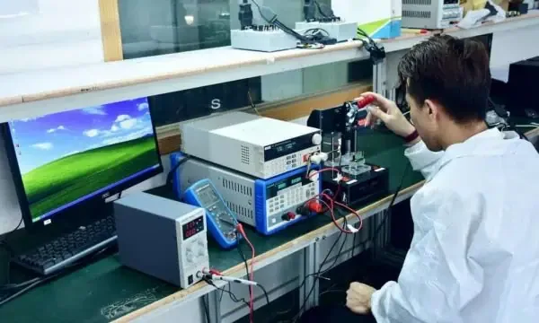
What is an FCT test for a PCBA?
FCT means functional circuit test. It applies defined power, inputs, loads and operating states to an assembled board, then compares specified responses with approved limits. A useful FCT result identifies the product, firmware, test sequence, fixture and observations. It answers whether the assembly met the tested requirements under those conditions, not whether every possible function and failure mode has been proved.
This page focuses on implementing a repeatable production test: fixture access, sequence, limits, cycle time, records and failed-unit handling. For the distinction between bare-board connectivity and populated-board operation, use the PCB versus PCBA testing explanation. The test-method comparison covers selection among AOI, X-ray, ICT and functional methods.
Start the FCT conversation while the schematic and layout can still support test access. A connector position, programming interface or missing observation point can change fixture complexity and coverage. The manufacturing quotation should identify whether test development, tooling, software, ongoing execution and records are included or supplied separately.
Turn product behavior into a testable requirement
A statement such as “check the board works” leaves the test engineer to guess the operating state and acceptance boundary. Break it into controlled conditions, stimulus, observation and limits. Include timing where it matters. Identify the software or firmware state that makes the expected response meaningful.
| Test element | Illustrative controller example | Why it matters |
|---|---|---|
| Requirement ID | PWR-01 | Connects the result to an approved requirement |
| Controlled state | Board revision C, released firmware and configuration | Prevents comparing incompatible builds |
| Stimulus | Specified supply and defined output load | Makes the observation repeatable |
| Observation | Rail voltage after the approved settling interval | Defines what the instrument measures |
| Limits | Drawing/test-specification lower and upper bounds | Separates measured value from judgement |
| Record | Serial, measured value, limits and test revision | Supports review and later investigation |
The example is a structure for a requirement, not a set of electrical limits. Use the product specification to establish actual values. Include relevant startup, reset, communication, analog, load and shutdown behaviors rather than assuming one boot message covers the whole board.
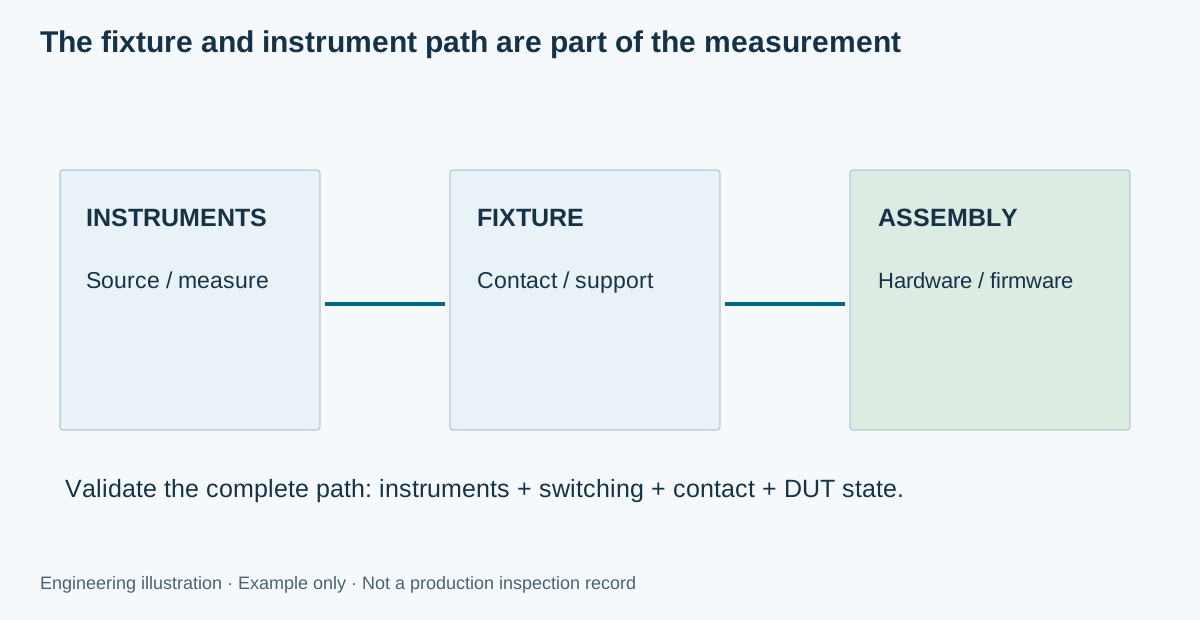
Design the fixture as part of the measurement path
A fixture establishes mechanical location and electrical contact while supporting the assembly. Connector mating, probe targets, board support and operator handling all affect repeatability. Keep the DUT orientation and allowed loading sequence unambiguous. A fixture with many contacts can still have poor coverage if the wrong nodes are accessible or the circuit cannot be stimulated as required.
Define the path from the instrument to the measured node, including cables, switches, probes and return connections. Contact resistance, shared grounds and loading can change the result. Where low resistance, small signals or fast edges matter, have the responsible test engineer choose the appropriate measurement arrangement and validate it against the requirement.
The DFA guide supports access and assembly discussions, but a functional test fixture also needs a product-specific electrical review. Account for hazardous energy, moving loads and interlocks in the actual test-system design. The planning tool on this page does not design a safe fixture or generate a wiring diagram.
Run a controlled sequence, not a collection of readings
An illustrative sequence begins with identity and fixture checks, then controlled startup, defined measurements and safe shutdown with record completion. The appropriate order depends on the product. A setup must not continue into a powered test when a prerequisite has failed simply because a later measurement might still return a number.
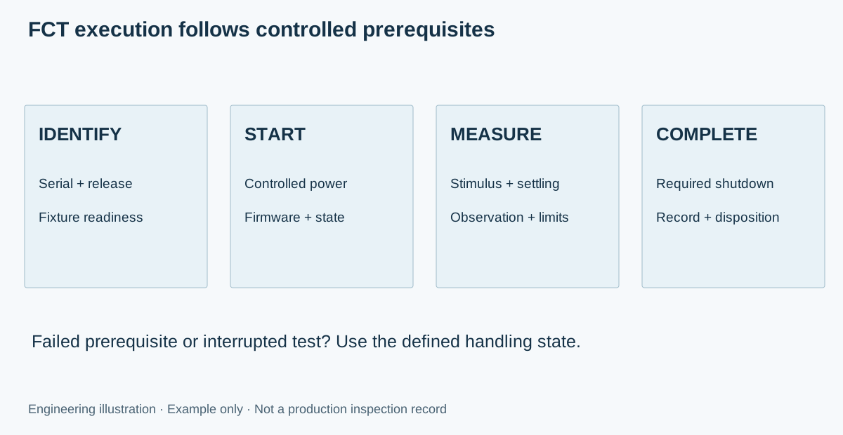
Verify the board and firmware identity before judging behavior. Establish the authorized power sequence and protective limits through the product-specific test design. Confirm communication and required configuration. Apply loads and inputs in the specified order, allow the defined settling time, then store measured values with their units and limits.
At the end, return the DUT and fixture to the required condition, remove or discharge energy as specified and complete the unit record. A software exception or lost communication should have a defined handling state. An interrupted test is not a pass, and an operator should be able to distinguish a DUT failure from a station error.
Plan the test cycle and explore the sequence
Enter measured or estimated durations for handling, startup/programming, measurements and shutdown. Each duration describes one complete fixture cycle for the entered number of simultaneously tested boards. The calculator does not divide a single-board measurement time by the number of sockets. Parallel operation must be supported by the actual instrument resources, fixture and software.
RAYPCB ENGINEERING
Quality PlanningFCT Fixture Cycle Planner
Loading FCT Fixture Cycle Planner…
Use the step controls to examine the conceptual sequence. Optional playback illustrates the stages; it is not a real test program or a record of powered equipment. A static sequence is available above. The download records the current assumptions so an engineering enquiry can distinguish estimated timing from measured production performance.
Example: fixture cycles and a realistic planning allowance
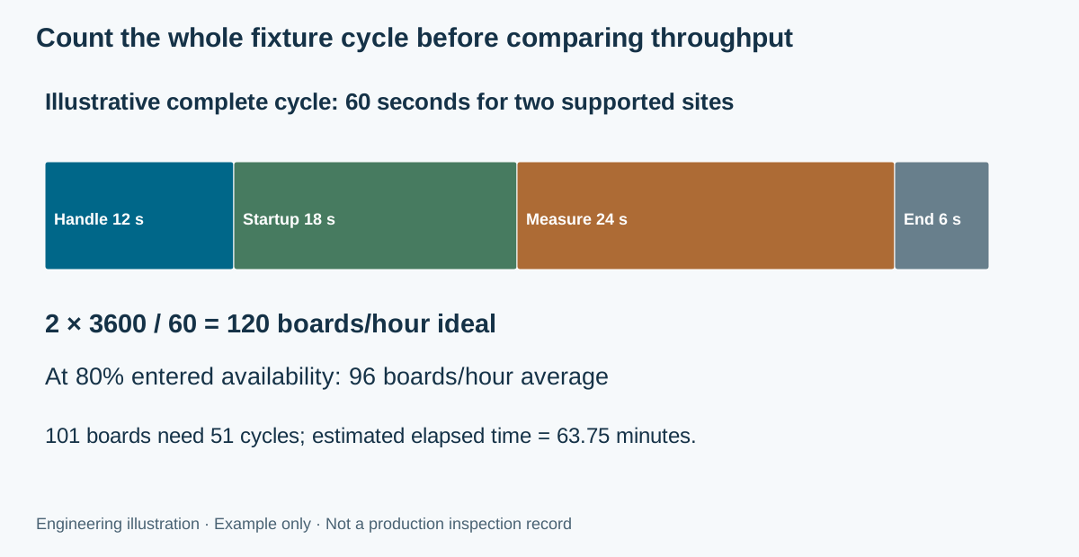
Suppose one illustrative cycle has 12 seconds of handling, 18 seconds of startup and programming, 24 seconds of measurements and 6 seconds of shutdown. The total is 60 seconds. With two independently supported DUT sites, the ideal arithmetic rate is 120 boards per hour. This assumes both sites complete together within those entered durations.
Using an entered 80% station-availability planning factor gives 96 boards per hour as an average rate. A lot of 101 boards needs 51 cycles, including a partly filled last cycle. At 60 seconds per cycle and the same availability factor, the estimated elapsed test time is 63.75 minutes. Setup, troubleshooting and retest are not added unless explicitly included in your timing assumptions.
This is capacity arithmetic, not a RAYPCB throughput claim. Shared instruments may serialize measurements, operator loading may dominate and a failed DUT may interrupt both sites. Measure the actual cycle before committing a delivery schedule or using the result to choose fixture quantities. Keep the quoted test scope constant when comparing alternatives.
Validate the station and the acceptance limits
Product limits and production test limits should be related through an approved measurement strategy. Instrument accuracy, uncertainty, fixture effects, settling and environment can matter near a boundary. A tighter-looking number is not automatically a better production limit. The responsible engineer must define and validate the decision rule for the application.
Use reference units and known conditions to challenge the station, not simply to show that one preferred sample passes repeatedly. A “golden board” can drift or contain an undetected issue. Control its identity and condition, and consider how the station responds to representative failures or boundary conditions that the test is intended to detect.
The NI functional-test overview discusses production test systems, parallelization and repeatable measurements. Instrument-vendor tools can support implementation, but they do not define your product’s limits or prove coverage automatically. Keep station validation evidence separate from the DUT’s production result.
Place FCT within the complete acceptance plan
FCT complements workmanship and structural inspection. IPC-A-610 and J-STD-001 may apply to the assembly acceptance and soldering requirements, but they do not supply a universal operating test for every circuit. The IPC assembly standards guide helps define that part of the agreement; the product owner must approve the functional requirements.
For component-level electrical questions, review ICT testing. For hidden-joint geometry, use the appropriate inspection method. A passing operational check does not demonstrate every physical joint is acceptable, just as a good-looking assembly does not demonstrate the correct firmware or output behavior.
Keep the coverage matrix explicit: required functions, operating states, observations, inaccessible conditions and supporting methods. Where a requirement cannot be verified in the selected production setup, record the gap and the agreed alternative. Do not convert a limited FCT into a general reliability, environmental or regulatory certification claim.
Keep each attempt linked to the unit
Record unit identity, hardware and firmware versions, fixture and sequence revision, instrument or station identity, timestamps, measurements, limits and disposition as required by the project. Store a clear status for interrupted tests and station errors. A report that contains only a green “pass” can be difficult to investigate when a later issue emerges.
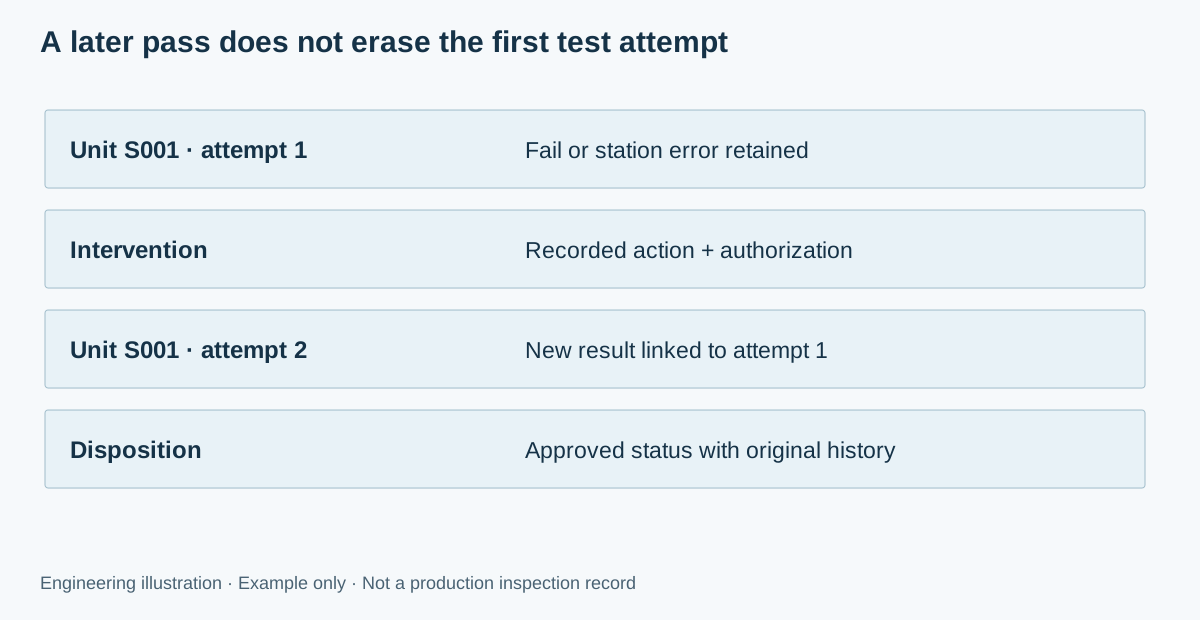
Preserve failed attempts and the reason for a retest. Repeatedly pressing test until a unit passes hides both product and station problems. If contact cleaning or fixture adjustment resolves an issue, distinguish that intervention from a component repair. Define who can authorize retest and which earlier measurements remain valid afterward.
The PCBA quality-control page connects the station result to containment, rework and process feedback. The traceability guide addresses retention and retrieval. Exported test data should remain interpretable after a fixture or software upgrade, with the original limits and revision available.
Prepare an FCT development and production enquiry
Provide the assembly revision, schematic, available interfaces, firmware process, functional requirements, quantities and desired records. State whether the test procedure, fixture or software already exists. Identify customer-supplied equipment and responsibility for maintenance, spare contacts, software changes and reference-unit control.
Separate one-time development and fixture work from per-board execution. Ask how changes in the board or firmware affect revalidation and pricing. If requirements are incomplete, label the enquiry as a scoping discussion and list the decisions still needed. You can proceed directly to PCB Assembly or contact RAYPCB without completing the calculator.
FCT test questions
Is a power-on check a complete functional test? Only if it covers the explicitly agreed requirement, which is usually a narrow one. Define the actual inputs, states, outputs and limits needed for the product.
Does adding sockets multiply throughput automatically? No. Instruments, stimulus resources, software and handling may be shared or serialized. Enter complete measured cycle times for the supported parallel configuration.
Can FCT replace burn-in or environmental qualification? No. They address different conditions and objectives. Specify each required verification activity independently instead of inferring it from a production FCT pass.
What happens after a failed test? Control the affected unit, retain the first result, distinguish a station fault from a DUT issue and apply the authorized review or rework process before any approved retest.
Scope your functional test requirements
Send the product revision, quantity, required standards and expected records. Identify unresolved limits, methods or responsibilities so the engineering review can address them before quotation or release.
Attach a downloaded tool brief manually. Contact does not automatically receive these inputs. References reviewed September 2026. Diagrams explain methods; published equipment photographs do not establish project results, certification or included test coverage.

