Static fold or repeated motion
Show the installed shape, bend zone, radius, direction and expected duty. Copper type and the complete flexible thickness govern the mechanical review.

RAYPCB / Manufacturing specifications
Check flexible layers, copper-dependent line spacing, coverlay, stiffeners, finishes and finished dimensions before releasing the flex drawing.
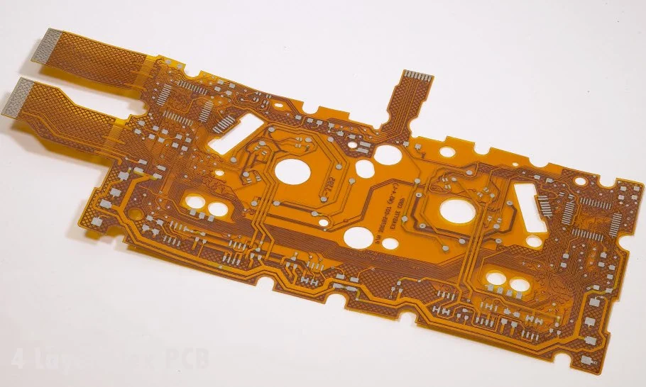
Use the matching construction and production window. Dimensions, copper and via limits must be reviewed together; an extended capability is confirmed against the released drawing.
Capability tables (CSV)| Parameter | Specification |
|---|---|
| Layers — flexible | 1–12 layers |
| Layers — rigid-flex | 2–32 layers |
| Base material | PI / DuPont Kapton, PET, PEN; FR-4 for rigid regions or stiffeners |
| Stiffeners | FR4, aluminum, polyimide, stainless steel |
| Copper thickness | 1/3 oz – 2 oz |
FR-4 is used for rigid regions or stiffeners; it is not a flexible base film. Rigid-flex total layers are included for comparison with the dedicated capability page.
| Parameter | Specification |
|---|---|
| Max / min board size | Minimum 0.2 × 0.3 in (5.08 × 7.62 mm); maximum 20.5 × 13 in (520.7 × 330.2 mm) |
| Final thickness — flexible | 0.002–0.1 in (≈0.05–2.54 mm); define each region |
| Final thickness — rigid-flex | 0.0024–0.16 in (≈0.06–4.06 mm); rigid-flex comparison range |
| Insulation thickness | 0.5–2 mil (12.7–50.8 µm) |
State thickness by region: flexible circuit, connector area and any locally reinforced area. The overall range does not define bend-region thickness.
| Parameter | Specification | Application notes |
|---|---|---|
| Min. trace width / space | 0.5 oz: 4/4 mil · 1 oz: 5/5 mil · 2 oz: 5/7 mil | |
| Min. annular ring | 0.5 oz: 4 mil · 1 oz: 5 mil · 2 oz: 7 mil | |
| Min. hole size | 8 mil | Confirm drilling vs finished diameter, hole depth and material. |
| Hole tolerance | PTH ±3 mil · NPTH ±2 mil | |
| Min. slot | 24 × 35 mil (0.6096 × 0.889 mm) |
Select the row for the actual copper weight. Minimum annular ring, hole diameter and trace clearance describe different dimensions.
| Parameter | Specification |
|---|---|
| Solder-mask / coverlay alignment tol. | ±3 mil |
| Silkscreen alignment tol. | ±6 mil |
| Silkscreen line width | 5 mil |
Coverlay openings and rigid-board solder mask have different fabrication steps. Mark their boundaries and tolerances separately.
| Finish | Specification |
|---|---|
| Immersion Nickel / Gold (ENIG) | Nickel 100–200 µin · Gold 1–5 µin |
| Gold plating (electrolytic) | Nickel 100–200 µin · Gold 1–4 µin |
| Immersion Silver | Silver 6–12 µin |
| Immersion Tin | Available |
| OSP | Film 8–20 µin |
Specify the nickel and gold layers separately. Finish thickness ranges do not imply every construction meets every IPC finish specification.
| Parameter | Specification | Application notes |
|---|---|---|
| Profile tolerance (punch) | Accurate mould ±2 mil · Ordinary mould ±4 mil · Knife mould ±8 mil · Hand-cut ±15 mil | |
| Test voltage | Testing fixture: 50–300 V | Electrical-test setting; not rated operating voltage. |
Choose the outline process on the drawing. Electrical-test voltage is a test setting, not the flex circuit’s rated operating voltage.
Show the installed shape, bend zone, radius, direction and expected duty. Copper type and the complete flexible thickness govern the mechanical review.
Dimension the final connector thickness, stiffener material and adhesive. Keep reinforcement boundaries out of the intended bend.
Map continuous copper and the local coverlay openings. Add support, tooling and the assembly sequence where components are fitted.
Flexible PCB manufacturing and design tools. Use the service-page tools for geometry or budget planning, or send your existing files directly for review.
Agree IPC-6013 for flexible / rigid-flexible board performance and IPC-A-600 for board acceptability, including revision, class and customer requirements. Request the relevant evidence against the part number and drawing revision.
IPC standards and their scope help separate manufacturing requirements from acceptance criteria.
Quality system and supplier documents · Inspection workflow · Equipment and process evidence

The listed combinations are 4/4 mil at 0.5 oz, 5/5 mil at 1 oz and 5/7 mil at 2 oz. Review finer geometry and bend-region routing with the actual stackup.
Specify it explicitly in the drawing. A reinforced connector region and the free-flex bend region can have very different finished thicknesses.
Cycle life needs a defined radius, motion, copper, stackup and qualification test. A layer count or minimum thickness alone cannot establish it.
Send what you have. Mark any requirement where you need an engineering recommendation, and identify the current revision.
Ready for a manufacturability review?
Upload the files through Contact. The reply can define pricing, delivery, process exceptions and the agreed test scope.
Send files for an exact quote