Introduction
In the high-stakes world of defense and aerospace, the reliability and performance of electronic systems can mean the difference between mission success and failure. At the heart of these critical systems lie Military PCBs (Printed Circuit Boards), the unsung heroes that enable everything from advanced communication networks to sophisticated weapons systems. These specialized PCBs are designed and manufactured to withstand extreme conditions, ensure unwavering reliability, and meet the stringent standards set by military specifications.
This comprehensive guide delves into the intricate world of Military PCB design and manufacturing, exploring the crucial factors that set these boards apart from their commercial and industrial counterparts. We’ll examine the stringent MIL-SPEC standards that govern their production, the unique materials and processes involved, and the best practices that ensure these PCBs meet the demanding requirements of modern military applications.
Whether you’re a defense contractor, an engineer working on aerospace projects, or simply interested in understanding the pinnacle of PCB technology, this article will provide you with invaluable insights into the world of Military PCBs. Let’s embark on this journey to uncover how durability, precision, and compliance converge to create the backbone of military electronics.
1. What Is a Military PCB?

Definition of Military PCB
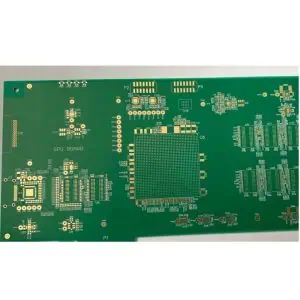
A Military PCB is a specialized printed circuit board designed and manufactured to meet the rigorous standards and specifications required by military and aerospace applications. These PCBs are engineered to operate reliably in extreme environments and under harsh conditions that would cause standard commercial PCBs to fail.
How Military PCBs Differ from Commercial and Industrial PCBs
Military PCBs stand apart from their commercial and industrial counterparts in several key aspects:
- Durability: Built to withstand extreme temperatures, shock, vibration, and humidity.
- Reliability: Engineered for extended operational life and minimal failure rates.
- Performance: Designed to maintain signal integrity under challenging conditions.
- Compliance: Adherence to strict military standards and specifications (MIL-SPECs).
- Materials: Use of high-grade, specially certified materials.
- Manufacturing Process: Rigorous quality control and documentation throughout production.
- Testing: Extensive testing protocols to ensure performance and reliability.
Common Applications of Military PCBs
Military PCBs find their way into a wide array of critical defense and aerospace systems, including:
- Advanced communication systems
- Radar and sonar equipment
- Avionics and flight control systems
- Missile guidance systems
- Satellite technology
- Electronic warfare systems
- Rugged portable devices for field operations
- Unmanned aerial vehicles (UAVs) and drones
2. Key Requirements for Military PCB Design
Durability Under Extreme Conditions
Military PCBs must be designed to operate reliably in environments that would quickly degrade or destroy standard electronics. This includes:
- Temperature Extremes: Functioning in temperatures ranging from -55°C to +125°C or beyond.
- Vibration and Shock: Withstanding high G-forces and constant vibration in aircraft and vehicles.
- Radiation Resistance: Operating in high-altitude or space environments with increased radiation exposure.
- Humidity and Moisture Resistance: Maintaining integrity in high-humidity or potentially wet conditions.
High Reliability and Long Lifecycle
The nature of military operations demands electronics that won’t fail at critical moments and can remain in service for extended periods. This requires:
- Component Selection: Using military-grade, high-reliability components.
- Redundancy: Implementing redundant circuits and fail-safe designs.
- Thermal Management: Effective heat dissipation to prevent premature component failure.
- Lifecycle Planning: Designing for long-term availability of components and potential future upgrades.
EMI/EMC Considerations in Design
Electromagnetic Interference (EMI) and Electromagnetic Compatibility (EMC) are crucial factors in military electronics:
- Shielding: Implementing effective EMI shielding techniques.
- Layout Strategies: Careful PCB layout to minimize EMI generation and susceptibility.
- Filtering: Incorporating appropriate filtering components to reduce EMI.
- Grounding: Proper grounding techniques to manage electromagnetic emissions and susceptibility.
Secure and Redundant System Design for Mission-Critical Operations
Military PCBs often form the backbone of mission-critical systems where failure is not an option:
- Fault Tolerance: Designing systems that can continue to function even if part of the circuit fails.
- Secure Design: Implementing features to prevent unauthorized access or tampering.
- Data Protection: Incorporating encryption and secure communication protocols at the hardware level.
- Redundant Power: Ensuring uninterrupted operation through redundant power supplies and circuits.
3. Understanding MIL-SPEC Standards

What are MIL-SPECs and Why They Matter
Military Specifications (MIL-SPECs) are a set of standards issued by the United States Department of Defense to ensure uniformity, quality, and reliability in military and aerospace equipment. For PCBs, these standards define:
- Material requirements
- Design parameters
- Manufacturing processes
- Testing procedures
- Documentation and traceability requirements
Adherence to MIL-SPECs is crucial because it:
- Ensures interoperability between different systems and components
- Guarantees a minimum level of quality and reliability
- Facilitates the procurement process for military projects
- Provides a common language between manufacturers and military customers
Key Military Standards Impacting PCB Design
MIL-PRF-31032 (Performance Specifications)
This specification covers the general requirements for printed circuits, including:
- Qualification and performance requirements
- Quality assurance provisions
- Marking and traceability
MIL-PRF-55110 (Rigid PCBs)
Focused on rigid printed circuit boards, this standard specifies:
- Material requirements for rigid PCBs
- Design and construction parameters
- Testing and inspection criteria
MIL-PRF-50884 (Flexible PCBs)
This standard addresses the requirements for flexible and rigid-flex printed circuits:
- Flex and rigid-flex material specifications
- Design guidelines for flexible circuits
- Unique testing requirements for flex PCBs
IPC-A-610 Class 3 (Acceptability of Electronic Assemblies)
While not a military standard per se, IPC-A-610 Class 3 is often specified for military projects:
- Defines the highest level of acceptance criteria for electronic assemblies
- Covers various aspects of PCB assembly, including soldering, component mounting, and cleanliness
How Compliance Impacts Procurement and Deployment in Military Projects
Compliance with MIL-SPECs has far-reaching implications:
- Qualification Process: Manufacturers must undergo rigorous qualification processes to be certified for military PCB production.
- Cost Considerations: Meeting MIL-SPEC requirements often increases production costs but is necessary for ensuring reliability.
- Lead Times: Compliance can lead to longer lead times due to additional testing and documentation requirements.
- Supply Chain Management: Only certified suppliers can be used, impacting the entire supply chain.
- Project Approval: Non-compliance can lead to project delays or rejections in military procurement processes.
- Field Performance: MIL-SPEC compliance directly impacts the reliability and performance of deployed military systems.
4. Materials Used in Military PCBs
High-Tg and Low-CTE Laminates
Military PCBs often utilize specialized laminates with specific characteristics:
- High Glass Transition Temperature (Tg): Materials like polyimide that maintain stability at high temperatures.
- Low Coefficient of Thermal Expansion (CTE): To minimize warping and stress on components during temperature fluctuations.
- Examples: Rogers 4350B, Isola IS620, and Panasonic MEGTRON6.
Metal Core PCBs for Thermal Management
In applications requiring superior heat dissipation:
- Aluminum or copper core PCBs are used to efficiently conduct heat away from components.
- These PCBs can handle higher power densities, crucial for radar and high-power RF applications.
Special Surface Finishes
Military PCBs often require specialized surface finishes for enhanced durability and reliability:
- ENIG (Electroless Nickel Immersion Gold): Provides excellent corrosion resistance and solderability.
- Hard Gold: Used in applications requiring high wear resistance, such as edge connectors.
- HASL (Hot Air Solder Leveling): Still used in some military applications, though less common due to lead concerns.
High-Reliability Solder Materials
Solder selection is critical in military PCBs:
- Lead-based solders: Still used in some military applications due to their reliability and exemption from RoHS regulations.
- High-reliability lead-free alternatives: Such as SAC305 (Tin-Silver-Copper) alloys for RoHS-compliant military projects.
Importance of RoHS and Non-RoHS Options
The choice between RoHS (Restriction of Hazardous Substances) compliant and non-RoHS materials depends on specific project requirements:
- Non-RoHS: Often preferred for critical military systems due to proven long-term reliability.
- RoHS-compliant: Increasingly adopted in less critical applications and to align with global environmental standards.
- Dual-compliance: Some manufacturers offer PCBs that meet both RoHS and non-RoHS requirements for maximum flexibility.
5. Military PCB Manufacturing Process
Overview of Manufacturing Steps
The manufacturing process for military PCBs follows a stringent set of procedures:
- Design Review: Thorough review of PCB design against military specifications.
- Material Selection: Choosing and verifying MIL-SPEC compliant materials.
- Inner Layer Processing: For multi-layer boards, including imaging and etching.
- Layer Alignment and Pressing: Critical for maintaining tight tolerances.
- Drilling: Precision drilling of holes and vias.
- Plating: Copper plating of holes and surface finish application.
- Outer Layer Imaging and Etching: Creating the final circuit patterns.
- Solder Mask and Legend: Application of solder mask and component markings.
- Final Finish: Application of the specified surface finish (e.g., ENIG, Hard Gold).
- Electrical Testing: 100% electrical testing of all boards.
- Final Inspection: Rigorous visual and dimensional inspection.
Special Manufacturing Controls for Military Projects
Military PCB manufacturing involves additional controls:
- Cleanroom Environments: To minimize contamination.
- ESD Protection: Strict electrostatic discharge protocols throughout manufacturing.
- Material Traceability: Detailed tracking of all materials used in production.
- Process Control Monitoring: Continuous monitoring and recording of critical process parameters.
Testing and Inspection Protocols
Military PCBs undergo extensive testing:
- Automated Optical Inspection (AOI): For detecting surface defects.
- X-ray Inspection: To check internal layers and hidden solder joints.
- Flying Probe and In-Circuit Testing: For electrical verification.
- Microsection Analysis: To verify internal structure and plating thickness.
- Environmental Stress Screening: Including thermal cycling and vibration testing.
- Functional Testing: To simulate operational conditions.
Certification and Documentation Processes Required
Comprehensive documentation is a hallmark of military PCB manufacturing:
- Certificate of Compliance: Documenting adherence to specified standards.
- Material Certifications: Proving the use of approved materials.
- Process Control Records: Detailed logs of all manufacturing processes.
- Test Reports: Results of all electrical and environmental tests.
- Traceability Records: Linking each board to specific batches of materials and process steps.
Read more about:
6. Design Best Practices for Military PCBs
Designing for Thermal Stability
Ensuring thermal stability is crucial for military PCBs operating in extreme environments:
- Thermal Analysis: Conduct thorough thermal modeling during the design phase.
- Component Placement: Strategically place heat-generating components for optimal heat dissipation.
- Thermal Vias: Implement thermal vias to efficiently transfer heat to other layers or heat sinks.
- Copper Pours: Utilize large copper areas for improved heat distribution.
- Material Selection: Choose PCB materials with appropriate thermal characteristics for the application.
Signal Integrity and Noise Mitigation Techniques
Maintaining signal integrity is paramount in military electronics:
- Controlled Impedance: Design traces with controlled impedance for high-speed signals.
- Proper Stackup Design: Optimize layer stackup for signal integrity and EMI reduction.
- Signal Isolation: Separate analog and digital signals to minimize interference.
- Shielding: Implement guard traces and ground planes for sensitive signals.
- Differential Pair Routing: Use differential pairs for high-speed and noise-sensitive signals.
Use of Redundant Circuits for Fault Tolerance
Redundancy is a key strategy in military PCB design:
- Duplicate Critical Circuits: Design multiple instances of critical circuit paths.
- Voting Systems: Implement triple modular redundancy for mission-critical functions.
- Backup Power Circuits: Design redundant power distribution networks.
- Failsafe Mechanisms: Incorporate circuits that default to a safe state in case of failure.
Design for Manufacturability (DFM) and Testability (DFT)
Optimizing designs for production and testing:
- Component Placement: Allow adequate spacing for assembly and rework.
- Test Point Allocation: Strategically place test points for in-circuit and functional testing.
- Panelization Considerations: Design with efficient panel utilization in mind.
- Standardization: Use standard component packages and footprints where possible.
- Documentation: Provide comprehensive design documentation to facilitate manufacturing and testing.
Importance of Robust PCB Stacking and Shielding
Proper layer stacking and shielding are critical for military PCBs:
- EMI Shielding Layers: Incorporate dedicated ground planes and shield layers.
- Layer Symmetry: Design symmetrical layer stacks to prevent board warpage.
- Embedded Capacitance: Use embedded capacitance layers for improved power integrity.
- Faraday Cage Techniques: Implement board-level Faraday cages for sensitive circuits.
- Edge Plating: Consider edge plating for additional EMI protection.
7. Common Challenges in Military PCB Projects
Long Lead Times for Specialized Materials
Military PCB projects often face challenges with material availability:
- Limited Suppliers: Fewer suppliers for MIL-SPEC certified materials.
- Custom Formulations: Specialized materials may require custom production runs.
- Stockpiling Strategies: Implementing strategies to maintain a stock of critical materials.
- Alternative Qualifications: Processes for qualifying alternative materials when primary options are unavailable.
Managing Strict Traceability and Documentation Requirements
The documentation burden in military projects is significant:
- Comprehensive Record-Keeping: Maintaining detailed records of all processes and materials.
- Version Control: Implementing robust version control for design files and documentation.
- Audit Preparedness: Keeping documentation ready for potential audits by military or regulatory bodies.
- Secure Data Management: Implementing secure systems for storing and accessing sensitive project data.
Balancing Performance vs. Cost Under Budget Constraints
Military projects often struggle with budget limitations:
- Cost-Effective Design Choices: Finding the right balance between performance and cost.
- Value Engineering: Identifying areas where costs can be reduced without compromising quality.
- Long-Term Cost Analysis: Considering lifecycle costs, not just initial production expenses.
- Negotiating with Suppliers: Working with suppliers to optimize costs for long-term projects.
Keeping Up with Rapidly Evolving Defense Technology Standards
The fast pace of technological advancement poses challenges:
- Continuous Education: Keeping design teams updated on the latest military standards and technologies.
- Flexible Design Approaches: Creating designs that can accommodate future upgrades or modifications.
- Collaboration with Military R&D: Engaging with military research to anticipate future requirements.
- Rapid Prototyping: Implementing agile development processes to quickly adapt to new standards.
8. Choosing the Right Military PCB Manufacturer
Key Qualifications to Look For
When selecting a manufacturer for military PCBs, consider these crucial qualifications:
- MIL-SPEC Certification: Verify that the manufacturer is certified to produce PCBs according to relevant military specifications.
- IPC Membership and Training: Look for manufacturers with active IPC membership and staff trained in IPC standards.
- ITAR Compliance: Ensure the manufacturer complies with International Traffic
Key Qualifications to Look For
- ITAR Compliance: Ensure the manufacturer complies with International Traffic in Arms Regulations (ITAR) for handling sensitive military technology.
- AS9100 Certification: This aerospace-specific quality management system certification is often required for military and aerospace PCB manufacturing.
- ISO 9001 Certification: A baseline quality management system certification that’s essential for any high-reliability manufacturing.
- NADCAP Accreditation: For manufacturers involved in aerospace applications, NADCAP accreditation demonstrates compliance with industry-specific quality standards.
Experience with Military and Aerospace-Grade Electronics
Look for manufacturers with:
- A proven track record in producing military and aerospace PCBs
- Familiarity with common military applications and their unique requirements
- Experience in handling classified or sensitive projects
- Capability to work with specialized materials and processes required for military PCBs
How to Verify Quality Assurance Systems
To ensure a manufacturer’s quality assurance meets military standards:
- Request and review their quality manual and procedures
- Ask for case studies or examples of previous military projects
- Inquire about their internal audit processes and corrective action procedures
- Check if they have dedicated military/aerospace quality assurance personnel
Importance of Supply Chain Security and Confidentiality
In military PCB manufacturing, security is paramount:
- Evaluate the manufacturer’s protocols for handling sensitive information
- Verify their cybersecurity measures for protecting design data
- Assess their supply chain management to ensure all materials and components are sourced from approved suppliers
- Check their policies on employee background checks and security clearances
9. Future Trends in Military PCB Design and Technology

Miniaturization and High-Density Interconnects (HDI)
As military equipment becomes more compact and sophisticated:
- Increased use of microvias and buried/blind vias
- Adoption of ultra-thin materials and finer line/space geometries
- Implementation of advanced packaging technologies like System-in-Package (SiP)
Use of Flexible and Rigid-Flex PCBs for Rugged Environments
To meet demands for lighter, more durable electronics:
- Growing adoption of flex and rigid-flex PCBs in wearable military technology
- Development of new flexible materials capable of withstanding extreme conditions
- Integration of flexible circuits in conformal antenna designs for aircraft and vehicles
Embedded Components for Enhanced Reliability
Embedding components within the PCB structure offers several advantages:
- Improved protection against harsh environmental conditions
- Enhanced signal integrity due to shorter interconnects
- Reduced overall size and weight of military electronics
Cybersecurity Considerations in Hardware
As cyber threats evolve, PCB design is adapting:
- Integration of hardware-based encryption and security features
- Implementation of anti-tamper technologies directly on the PCB
- Design of PCBs with built-in intrusion detection capabilities
Role of AI, 5G, and Advanced Materials in Military Electronics
Emerging technologies are shaping the future of military PCBs:
- AI-driven design optimization for complex military PCBs
- Integration of 5G capabilities for enhanced battlefield communication
- Exploration of novel materials like graphene for next-generation military electronics
Conclusion
Military PCB design and manufacturing represent the pinnacle of electronic engineering, where precision, reliability, and compliance converge to create the backbone of modern defense systems. Throughout this comprehensive guide, we’ve explored the intricate world of Military PCBs, from the stringent MIL-SPEC standards that govern their production to the cutting-edge technologies shaping their future.
The critical role that Military PCBs play in ensuring defense success cannot be overstated. These specialized circuit boards form the foundation of communication systems, weapons platforms, and surveillance equipment that safeguard nations and support military operations worldwide. As we’ve seen, the design and manufacturing processes for these PCBs are far more complex and demanding than those for commercial electronics, reflecting the high-stakes environments in which they must operate.