
RAYPCB · ENGINEERING GUIDE
EMI vs EMS vs EMC: Connect the Terms to the Engineering Task
EMI describes electromagnetic interference. In an EMC discussion, EMS commonly refers to electromagnetic susceptibility, while EMC describes compatibility in the intended electromagnetic environment. These terms help separate the disturbance source, the equipment's response and the overall engineering objective.
EMS can also mean electronics manufacturing services in another context. This page addresses susceptibility and EMC terminology; the manufacturing business has a separate service route. The task classifier helps identify which engineering question a visitor is actually asking.
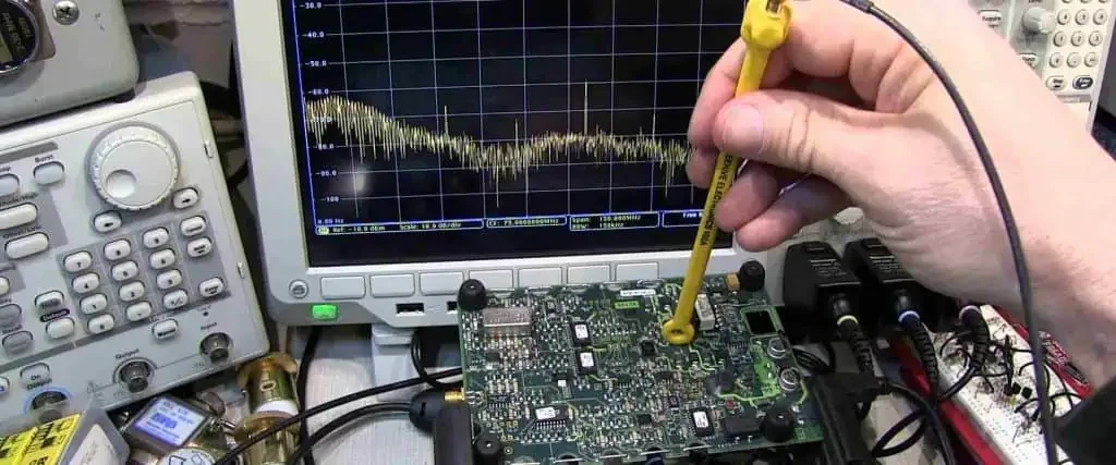
Start with the direction of the problem
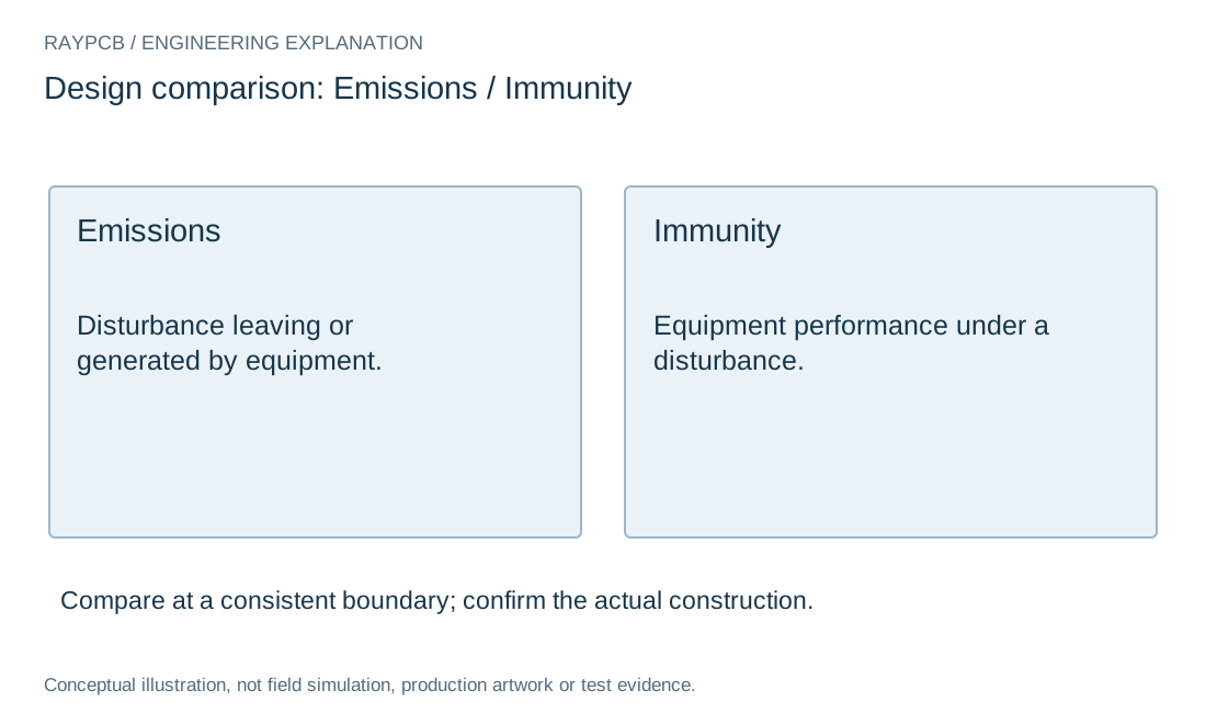
If equipment produces an unwanted disturbance that affects something else, the investigation includes its emissions and coupling paths. If equipment malfunctions when exposed to a disturbance, the investigation concerns immunity or susceptibility. The same assembly can be involved in both directions.
Describe the observation before choosing a label. A receiver loses sensitivity when a local processor operates is more informative than saying the board has an EMC issue. It identifies an affected function and a condition that can be tested.
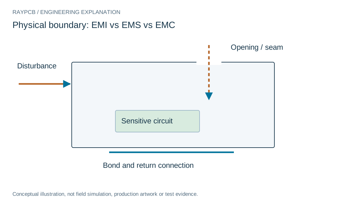
Terms connected to a practical task
| Term | Engineering meaning | Useful next question |
|---|---|---|
| EMI | Unwanted electromagnetic disturbance or interference. | What source, coupling path and affected function are observed? |
| EMS in EMC work | Susceptibility to a disturbance. | What stimulus and functional criteria define the response? |
| EMC | Compatibility in the intended electromagnetic environment. | Which emissions and immunity requirements apply to the product? |
| EMS in procurement | Electronics manufacturing services. | Which assembly and program services are required? |
Distinguish interference from an emissions number
An emission measurement describes a quantity under a defined test setup. Interference describes an unwanted effect or interaction. A measured peak can indicate a risk, but its relevance depends on the path, victim and applicable requirement.
Keep the measurement units and setup with the result. A near-field scan, cable-current reading and chamber electric-field measurement do not report the same quantity, even when their traces share a frequency axis.
| Review item | What to establish |
|---|---|
| EMI | Unwanted disturbance and its effect are described. |
| EMS | Susceptibility meaning is separated from manufacturing services. |
| EMC | Whole-product requirements include emissions and immunity. |
| Task | Observation leads to a specific investigation. |
Understand susceptibility and immunity
Susceptibility concerns the tendency to be affected by a disturbance; immunity describes the ability to maintain the required behavior under specified conditions. The test needs a defined stimulus and functional performance criteria.
For a digital controller, a reset may be unacceptable even if the hardware remains physically undamaged. For another function, temporary degradation may be assessed differently by the applicable requirement. Do not replace those criteria with a universal survives/does-not-survive statement.
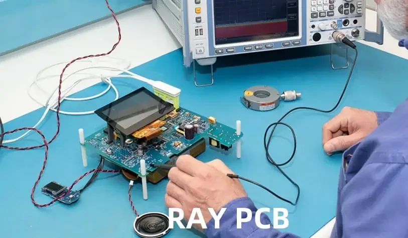
Treat EMC as a system objective
Compatibility requires attention to both the equipment's disturbance behavior and its response to the environment. Board construction, enclosure, cables, peripherals and software modes can all influence the outcome.
The PCB EMC planning guide turns this objective into requirements and evidence. It separates board-level design work from the final product configuration so a local improvement is not misrepresented as whole-system compliance.
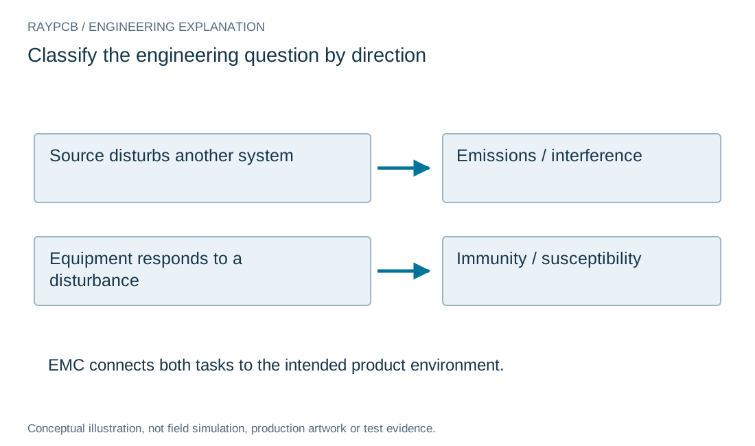
EMC task classifier
EMC task classifier
Use the current inputs and keep the assumptions
Start with the physical boundary named above the inputs. Enter your own values, or select Load example to explore the labeled teaching case. Example mode remains visible after edits so an illustrative result is not mistaken for measured project data. Clear for my inputs removes the sample values and starts a separate record.
Generate the result after completing the relevant fields. Changing an input invalidates the previous output and disables its download until you calculate again. Read the limitations next to the result: a ratio, margin or checklist does not qualify a channel, approve an EMC test or establish a supplier capability.
Download the current result if it supports your review. The text file contains inputs, outputs, assumptions and the tool version. It stays on your device; attach it manually to an enquiry if useful. No CAD or measurement file is uploaded or interpreted, and nothing is automatically inserted into the Contact form. You can ask an engineering question without completing this tool.
| Input | What to establish before using it |
|---|---|
| Review reference | Nonconfidential scope or revision. |
| What is being observed? | Choose the observed direction, not a certification claim. |
| Observed symptom / test condition | No private project data; free text is not verified. |
Separate conducted and radiated paths
Conducted paths involve electrical connections such as power and signal wiring. Radiated coupling involves fields, but the physical system can connect the mechanisms: currents on cables can contribute to radiation, and fields can induce currents in conductors.
Use a source-path-victim sketch instead of treating the categories as isolated boxes. That sketch helps determine whether the next investigation should focus on a filter, return connection, shield boundary or source behavior.
Choose the correct measurement language
An EMI receiver may report a corrected field strength or conducted voltage using a specified detector and bandwidth. An immunity test reports functional behavior under a defined stimulus. These results require different records and should not be merged into one generic noise score.
The receiver measurement guide explains one correction chain. It also shows why a positive arithmetic margin does not automatically include uncertainty or establish a formal compliance decision.
Use the classifier as a starting point
Select the direction that best describes the observed problem and write a short nonconfidential condition. The tool returns an appropriate task category and keeps the observation in a local summary. It cannot determine a standard, inspect a board or verify a test result.
If the issue is not repeatable yet, record that uncertainty. The next useful step may be creating a repeatable operating condition rather than selecting a shielding material or adding a suppression component.
Move from terminology to a review
Provide the affected function, operating mode, interface, disturbance evidence and relevant product requirements. Use EMC troubleshooting for a failure investigation or EMI protection for a mechanism-based intervention study.
For a RAYPCB enquiry, state the board or assembly change under consideration and the manufacturing scope. Understanding the terms improves that conversation, but tool completion is not required and no classification on this page certifies the equipment.
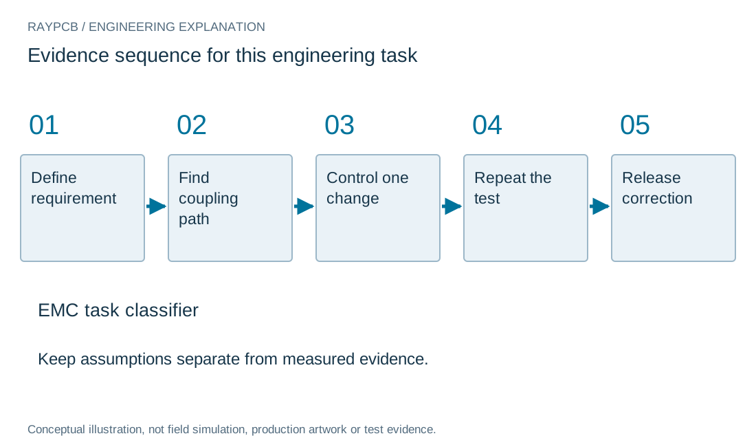
Use a source, path and victim record
Describe the disturbance source, its coupling path and the circuit or external system affected. This framework helps choose a testable change. It does not require knowing every field distribution before beginning, but it does require a hypothesis more specific than saying that the board has noise.
Record the product operating mode, software revision, cables, enclosure and power source. A bench configuration that omits those elements can be valuable for isolation, yet should not be mistaken for the final product configuration. Mark temporary diagnostic modifications separately from changes approved for production.
Plan regression checks when a change improves the suspected mechanism. A slower edge, filter, shield or different bond can affect timing, thermal behavior, service access or immunity as well as emissions. Evaluate the relevant tradeoffs before freezing the revised schematic, layout or mechanical drawing.
Turn the design decision into a controlled record. Keep the schematic and layout revision, model source, operating case and requirement together. Distinguish an entered assumption from a supplier nominal value and a measured result. If an important value is missing, record the unresolved question rather than replacing it with a convenient typical number.
Compare alternatives at a consistent boundary. Preserve the baseline and change one relevant variable when possible. If several features change together, describe the outcome as a comparison between configurations; do not assign the entire improvement to the one component you wanted to justify. Keep both favorable and unfavorable frequency regions in the evidence.
Before a repeat order, check whether substitutions affect the reasoning. A package change, alternate dielectric, shield finish or assembly operation can invalidate an earlier comparison even when the visible board outline is unchanged. Specify which changes need engineering review and which are already accepted. This makes the purchasing and manufacturing handoff useful without asking either team to reconstruct the original electrical investigation.
Standards, source context and limits
Use the applicable device documentation, interface specification and test-method edition for actual requirements. The public sources below explain particular methods; they do not certify the board on this page or replace a licensed standard. Match the document to the selected device, construction and end product before applying a numerical rule.
Numeric examples are teaching inputs unless explicitly identified otherwise. Archive photographs provide physical context, not current factory, customer-project or inspection evidence. Original drawings explain the stated model and are not production artwork, field-solver output or measured waveforms. No search ranking, compliance outcome or manufacturing limit is inferred from these illustrations.
For fabrication scope and the agreed construction requirements, see PCB manufacturing.