
Application engineering · Manufacturing review
Industrial PCB Manufacturing: Control, Power & Reliability
Design an industrial control board around its field wiring, supply interruptions and service life. Review power integrity, isolation boundaries, test access and a release package for fabrication or assembly.
Preliminary files are welcome. Identify the board revision, quantity and the question you need to resolve.
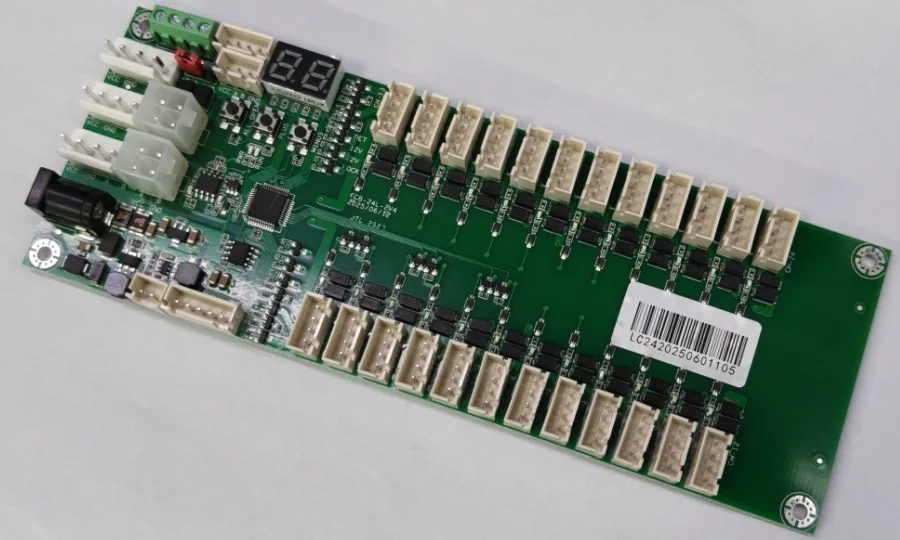
Industrial PCB: design for the installation, not just the enclosure
An industrial PCB connects electronics to an environment that may contain long cables, inductive loads, electrical noise, condensation and technicians replacing modules years after release. The board might be a PLC input module, a motor-control interface, a machine sensor, an HMI or a network gateway. Those applications share a need for predictable behavior, but they do not share one stackup, isolation rating or test program. Start with what crosses the enclosure boundary and what the equipment must do when that connection fails.
For a purchasing engineer, the useful question is not simply whether a supplier makes industrial boards. It is whether the proposed fabrication and assembly route supports the actual laminate, finished copper, connector loading, cleaning process and verification plan. RAYPCB can review a defined enquiry for bare-board manufacture or assembly. Identify which scope you need, the drawing revision and the decisions still open. A preliminary discussion is most productive when uncertainty is visible instead of hidden behind an apparently complete specification.
| Decision | Why it matters | Bring to the review |
|---|---|---|
| Supply interruption | Hold-up energy, converter behavior and controller recovery | Supply range, interruption profile and essential load |
| Field wiring | Protection, filtering and connector mechanics | Cable interfaces, external loads and fault response |
| Repeat service | Revision identity and component availability | Approved BOM, test limits and change ownership |
Map the board by energy and signal paths
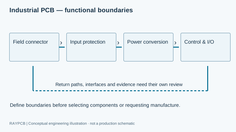
A field connector is an electrical entry point and a mechanical load. Place protection so incoming disturbances do not first cross the sensitive part of the board. Keep the high-current route through protection and conversion identifiable, and treat its return as part of the circuit. A quiet ADC input is not made quiet merely by giving its ground net a different name. Review where currents actually close their loops and where a return path changes reference.
Separate the requirements for 24 V distribution, analog measurement, isolated communication and digital control. A four-layer construction can provide useful routing and reference planes, but layer count alone does not prove EMC performance. The choice depends on component density, impedance needs, heat spreading and connector placement. Discuss multilayer PCB construction when routing and plane continuity are the constraint. Use an isolation boundary only where the system architecture requires one, with distances derived from the applicable working voltage and environment.
Engineering workbench
Industrial Supply Hold-up Planner
Explore the worked example or enter your own assumptions. The result explains the calculation boundary and can be downloaded for an engineering enquiry. No project data is uploaded by this tool.
RAYPCB ENGINEERING
Industry EngineeringIndustrial Supply Hold-up Planner
Loading Industrial Supply Hold-up Planner…
Calculate supply hold-up before increasing capacitance
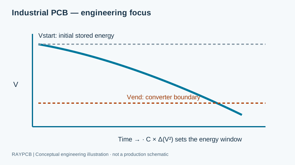
The interactive planner uses capacitor energy between an initial voltage and the minimum usable converter input. For an approximately constant output power, the idealized hold-up time is C × (Vstart² − Vend²) × efficiency / (2 × power). It uses effective capacitance, not an unqualified nominal label. For 470 µF, 24 V falling to 18 V, 85% efficiency and a 5 W load, the result is about 10.1 ms. This is a first energy check, not a prediction of a measured brownout waveform.
Real behavior also depends on ESR, converter undervoltage lockout, load steps, leakage, capacitance tolerance, temperature and aging. Adding capacitance can increase inrush and restart stress. A design that survives a brief supply dip may still lose communication state or corrupt a write operation. Define what must remain powered, how the controller detects the event and whether graceful shutdown is preferable to trying to sustain the whole product. Check the dynamic waveform on the released hardware.
The TI hold-up energy application note explains why constant-power, constant-current and resistive loads have different discharge behavior. The planner uses the constant-power case with a fixed conversion-efficiency assumption. Record the load model beside the calculated result so a later reader can understand what the number represents.
Select the protection IC with its external circuit
An industrial eFuse, ideal-diode controller or protected switch can simplify an input architecture, but their functions differ. Compare operating voltage, allowable transient exposure, current limit behavior, reverse polarity handling, fault response, thermal dissipation and restart mode. The TI TPS2660 product documentation provides an example of an industrial protection family and links to evaluation documentation. The exact variant and external components determine the implemented behavior; the example is not an approved part substitution.
Use the manufacturer's evaluation schematic as a reference to investigate, not as a complete schematic for your installation. Check connector ratings, fuse coordination, TVS selection, stored energy and the converter that follows the protection stage. Keep a component decision table with the maximum required operating voltage, anticipated abnormal conditions and evidence for each selection. The drawing on this page deliberately shows functional blocks rather than unverified component values. A project schematic requires the actual requirements and a design review.
Materials, copper and mechanical constraints
Choose laminate using the actual thermal exposure, thickness, dimensional stability and electrical requirements. A higher Tg value is not a substitute for checking the assembled product temperature or the complete material specification. Connector-heavy boards also need consideration of insertion forces, mounting locations, edge clearance and support during assembly. A heavy terminal block next to an unsupported board edge can make mechanical reliability the governing issue even when the electrical layout looks generous.
Copper selection should follow current, voltage drop, temperature and manufacturing constraints. Thicker copper may reduce resistive loss but changes etching, spacing and lamination requirements. Before specifying it everywhere, identify which conductors need the extra cross-section and whether busbars or a separate power stage are more appropriate. The power PCB design guide explains loss and switching-loop concerns. Keep the approved stackup and the distinction between base and finished copper in the fabrication package.
Field interfaces and fault behavior
An analog input connected to a long cable has a different risk profile from an on-board sensor. Document expected signal range, common-mode exposure, filtering and protection, including how an open or shorted cable is recognized. A 4–20 mA input also needs a burden and compliance-voltage review across the loop; the resistor value is not chosen only for a convenient ADC voltage. Label test points so a technician can measure the intended node without accidentally shorting nearby power conductors.
For RS-485, CAN, Ethernet or another interface, use the transceiver and protocol requirements for termination, topology and protection. Do not apply one interface's termination arrangement to another. Decide whether communications may continue during an input fault and how the system returns to service. Industrial reliability includes recoverable behavior and useful diagnostic information. Test the fault response at system level, including the cable, enclosure and power source, because a bare-board continuity check cannot establish it.
Manufacturing and inspection should follow failure modes
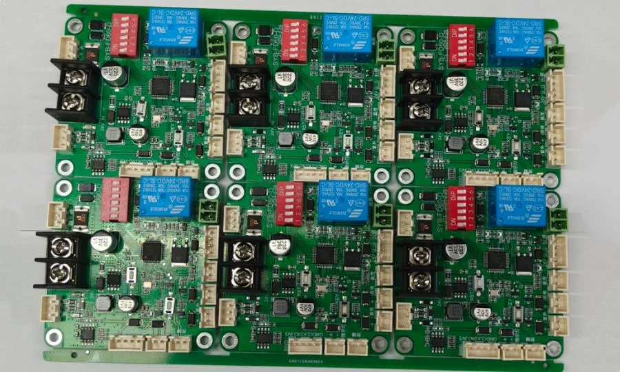
The fabrication review should address drill quality, annular geometry, copper balance, isolation slots, outline tolerance and any controlled-impedance structures. Assembly planning should address moisture-sensitive components, large thermal masses, connector soldering, cleaning compatibility and fixture access. Conformal coating, if specified, needs its own material, masking, cure and inspection agreement. It is not a universal repair for inadequate creepage, trapped contamination or unsuitable connectors.
Use design for assembly to resolve access and process conflicts before ordering. AOI can help find visible assembly defects; X-ray can support inspection of hidden features when applicable. Neither verifies a sensor transfer function or recovery from a supply interruption. A useful functional test has a defined stimulus, operating condition, output limit and record. Keep acceptance criteria separate from an operator's informal observation that the board appears to work.
Cost and quotation: separate the recurring board from engineering work
The recurring cost depends on board area and panel utilization, material availability, copper construction, drilling, finish, components, assembly operations and test time. Fixtures, programming development and first-build investigation may be non-recurring. A lower bare-board price can be overwhelmed by manual calibration or an awkward connector soldering process. Compare quotations using the same released requirements and the same inclusion of test, coating, packaging and traceability.
For a useful RFQ, provide the fabrication output, stackup, mechanical drawing, quantity and delivery need. Add the BOM with exact part numbers, placement data and assembly drawing for PCBA. Describe the installation, supply range, cable interfaces and any customer-selected workmanship criteria. If a test fixture does not exist, state that clearly and describe the required measurements. We can then discuss what needs engineering definition before a firm build scope can be agreed.
A practical pilot-build sequence
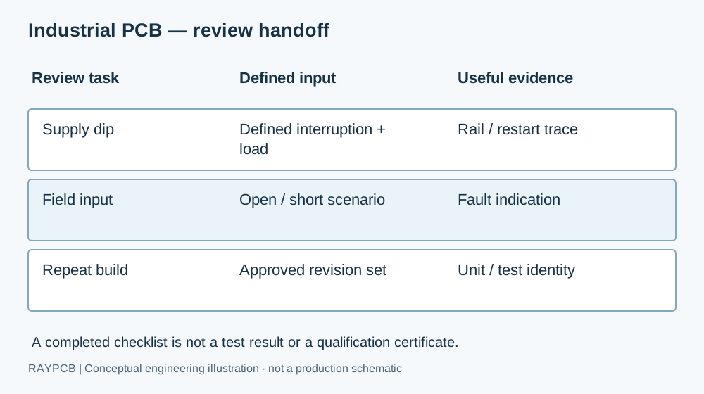
First freeze the requirement set and identify the revision used for purchasing. Next resolve the manufacturing questions and approve any component alternatives through the design owner. For the pilot, record the test setup and first-build findings in a way that can be reused for the next lot. A good pilot does more than deliver working samples: it reveals whether the files, fixture and acceptance instructions produce consistent decisions across operators.
Keep field feedback connected to the serial or lot record. If a connector, capacitor or firmware revision changes, determine which verification needs repeating and what happens to work already in progress. For ongoing OEM programs, electronic contract manufacturing is the appropriate conversation about repeatability and lifecycle ownership. For a fabrication-only requirement, return to PCB Manufacturing with the approved board specification.
For a motion-control project, the robot PCB current-sensing guide develops the shunt, Kelvin-routing and amplifier-headroom review. Keep the machine-level interface and supply requirements here, then use the specialized guide for that measurement path rather than repeating the same general checklist on both pages.
Questions engineers ask
Does an industrial PCB always need heavy copper?
No. Use the electrical loss and temperature requirement to identify where thicker copper is useful. Dense signal routing, isolation geometry and fabrication tolerance may favor another construction or a separate power path. A current figure without its conductor geometry and cooling conditions is not a meaningful board rating. ### Does the planner confirm a supply dip will be tolerated? No. It estimates stored energy under the stated constant-power assumptions. Converter behavior, capacitor characteristics and system state must be checked on hardware. Use the downloaded brief to document assumptions and request a review, not as a production acceptance record. ### Which files can I send before the design is finished? Send the available schematic, preliminary board data and a clear list of open issues. State which files are reference-only. A useful early review can focus on the supply architecture, connector arrangement or stackup without pretending the entire product is ready for manufacture.
A focused next step
Bring the requirement. Identify the open question.
Send the available board files, quantity and revision with the operating conditions discussed above. State whether you need bare boards, assembly or a broader manufacturing scope.
Use the downloaded brief to explain your assumptions. The Contact form is independent; it does not automatically receive calculator entries. A project review determines the quotation and agreed build scope.
Technical references reviewed September 2026. Illustrations explain concepts. Product and equipment photographs do not establish project-specific qualification, test results or certification.