
RAYPCB · ENGINEERING GUIDE
FPC Connector Selection: Tail Thickness, Contact Side and Fit
FPC connector selection begins with a matched pair of drawings: the connector and the finished flexible tail. Pitch and contact count are only the first checks. Finished tail thickness, contact-side orientation, exposed length, retention geometry, actuator access and the installed bend route determine whether the interface can be assembled consistently.
The thickness-envelope tool compares an entered tail tolerance with entered connector limits. A successful comparison addresses thickness alone; it does not approve the connector or create a land pattern.
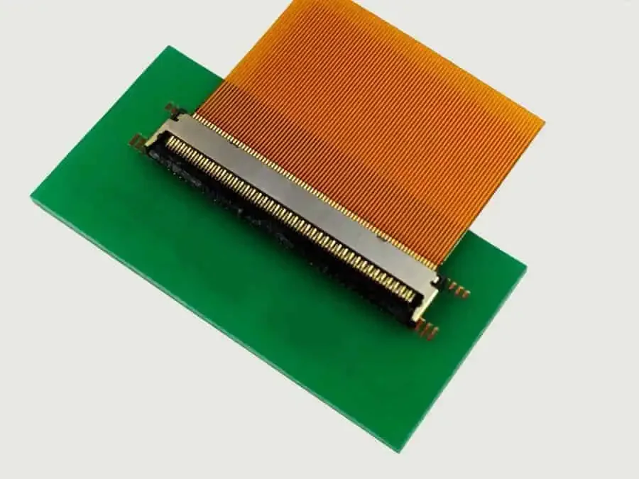
Choose the interface before finalizing the tail
Record the exact part number and current drawing revision. Similar-looking connectors can have different mating geometry, contact arrangements, locking features or recommended processing. Specify a controlled alternative rather than allowing substitution by pitch alone.
Include the intended mating cycles, environment and service access. A prototype connector that is convenient during development may not be the preferred interface for the final enclosure and production assembly method.
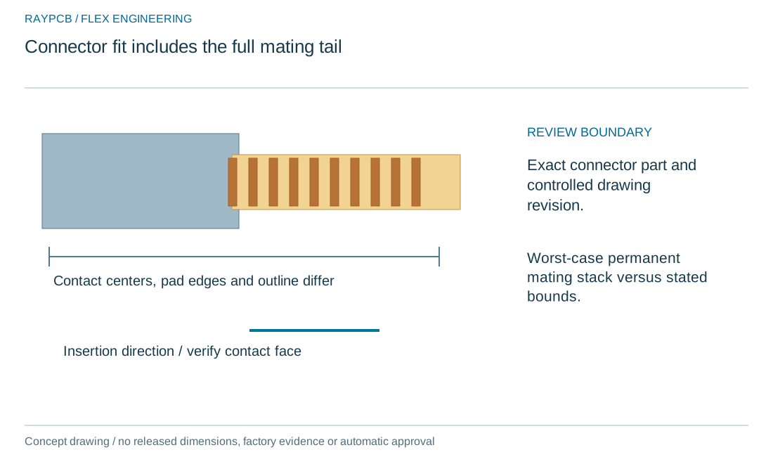
Calculate the permanent mating thickness
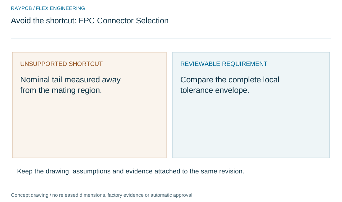
The mating region may include copper, finish, dielectric, adhesive and a stiffener. Identify the connector's thickness datum and compare the full finished envelope. Do not measure an unreinforced portion of the flex and treat it as the tail thickness.
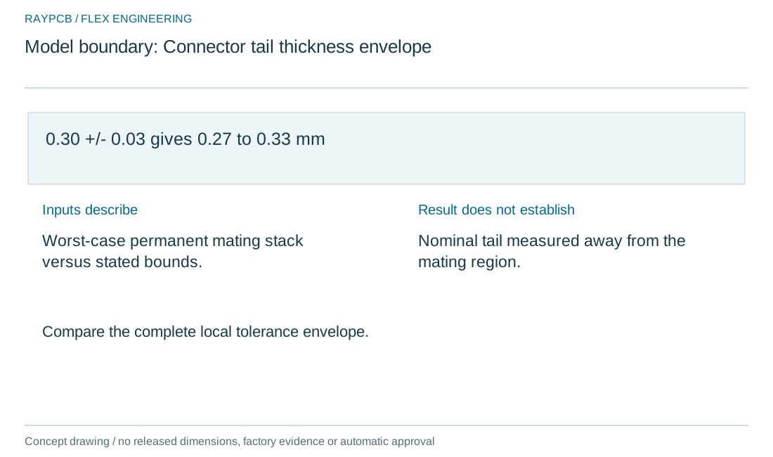
For illustration, a 0.30 ±0.03 mm tail spans 0.27–0.33 mm. Compared with entered limits of 0.25–0.35 mm, the numerical margins are 0.02 mm at both ends. Those example values are not a recommendation for an unspecified connector.
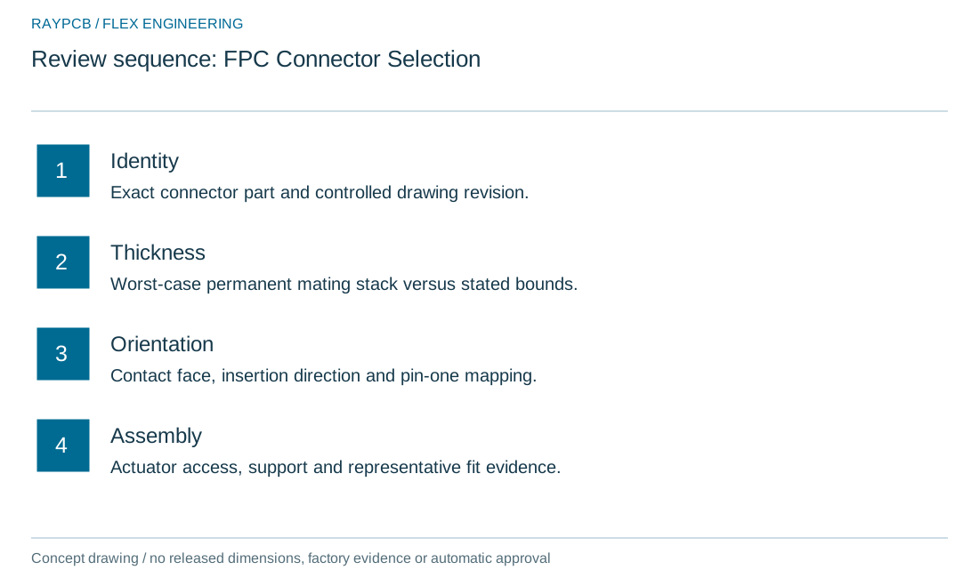
| Review item | What to establish |
|---|---|
| Identity | Exact connector part and controlled drawing revision. |
| Thickness | Worst-case permanent mating stack versus stated bounds. |
| Orientation | Contact face, insertion direction and pin-one mapping. |
| Assembly | Actuator access, support and representative fit evidence. |
Connector tail thickness envelope
Connector tail thickness envelope
Use the current inputs and keep the assumptions
Choose the engineering question before entering data. Every field begins blank. Load example provides teaching values so you can inspect the calculation or workflow; it is not a recommendation for dimensions, materials, operating conditions or prices. The example label remains visible after editing. Reset the worksheet before preparing a record based entirely on your own project inputs.
Keep the units and measurement boundaries consistent. A finished thickness is different from an incoming film thickness; a complete current loop is different from one conductor; a bulk dielectric constant is different from effective permittivity. Identify the source and conditions of the values you enter. If information is missing, record it as an engineering question instead of selecting an attractive assumption.
Read the result together with its limitations. A positive geometric margin addresses only the dimensions entered. An evidence checklist records your statements without checking the underlying documents. A cost scenario adds your allowances without supplying current market prices. None of these tools approves a material substitution, predicts service life or issues a manufacturing quotation.
Editing an input invalidates the current result and disables its download until you run the worksheet again. The text download contains the inputs, results and stated limitations. Processing stays in this browser; the tool does not read CAD, upload project files or send your inputs to analytics. No parameters are automatically passed to Contact. Download and attach the record manually if useful, or contact RAYPCB directly without using the tool.
| Input | What to establish before using it |
|---|---|
| Review reference | Use a nonconfidential revision or scope reference. |
| Finished tail nominal · mm | Include all permanent copper, finish, film, stiffener and adhesive. |
| Tail bilateral tolerance · mm | Same magnitude above and below nominal. |
| Connector allowed minimum · mm | Use the exact current drawing. |
| Connector allowed maximum · mm | Use the same drawing and mating section. |
Confirm contact side and pin numbering
Show the tail as viewed from an unambiguous side and identify pin one. Trace that numbering through the mating connector to the board netlist. A folded route can reverse the apparent order in a drawing even when the physical connector has not changed.
Use an actual assembly view to resolve top-contact, bottom-contact or other vendor terminology. The Molex footprint review demonstrates why a series name is insufficient for selecting a library footprint or orientation.
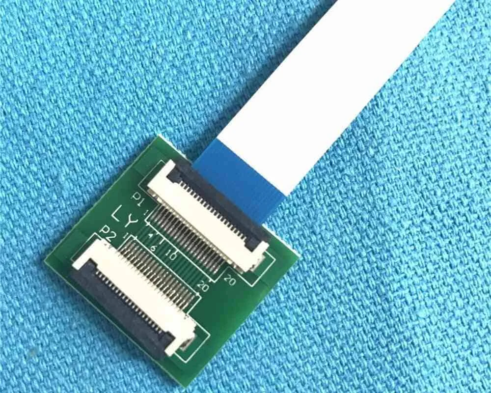
Reserve room to operate the actuator
Check the enclosure, adjacent components and tools needed for insertion and locking. The assembler needs enough access to insert the tail squarely without damaging exposed contacts or loading the circuit at a stiffener boundary. A connector that fits the PCB footprint may still be inaccessible in the product.
Include retention and cable routing in the review. Do not assign the connector the job of absorbing uncontrolled bending or pull loads from a moving flex. Mechanical supports need their own defined relationship to the mating interface.
Review current and signal requirements separately
Use the exact connector ratings and their stated conditions, then assess the actual contacts in use. Paralleling contacts does not guarantee equal current sharing. Temperature, conductor resistance and the mating state influence the complete path.
For battery interfaces use FPC battery connector planning. For high-speed routing, consider launches and returns as part of the USB FPC path, not simply as a pitch-selection problem.
Verify with representative assembled parts
Check insertion, locking, retention and electrical continuity using the intended tail construction and board assembly. Review extremes where practical, including thickness tolerance and the installed cable route. A nominal CAD fit does not reveal every handling or contact problem.
Retain the part numbers, material stack and revisions with the evaluation. If a stiffener adhesive or finish changes, assess whether the evidence still represents the new mating region.
Send an interface-focused enquiry
Provide the connector drawing, proposed tail stack, contact-side view, net mapping, installed route, assembly sequence and quantities. State unresolved thickness or access questions directly. RAYPCB can review the printed-circuit construction against the supplied interface requirements.
If the construction choice itself remains open, compare FFC and FPC first. For the geometrical envelope of a contact row, use flat flex circuit geometry.
Review the complete mating interface
Start with the exact mating pair and their controlled drawings. Record complete part numbers, contact count, variant and document revision. Family names are useful for browsing catalogs but can conceal different contact arrangements, mounting features and operating conditions. A purchasing alternative should be treated as an engineering substitution until its relevant differences are reviewed.
Separate three geometries: the board land pattern, the connector body and operating envelope, and the flexible mating tail. The dimensions in one do not automatically define the others. Show the assembly in a view that makes contact side, insertion direction, actuator movement and pin numbering unambiguous.
Trace the electrical mapping through the interface. Check the schematic symbol, footprint, assembly orientation, connector contacts and flex nets together. A mirrored view or folded route can make an incorrect mapping look plausible. Preserve a pin-one reference and an installed view in the release package rather than relying on an informal explanation.
Review the full permanent tail stack against the drawing's thickness limits. Include reinforcement, adhesive and finish where they fall inside the mating region. Use a stated tolerance envelope and datum. A nominal fit is not enough if manufacturing extremes can move the tail outside the allowed range.
Check the assembler's task in the real enclosure. Can the tail be inserted squarely and the actuator operated without loading a vulnerable circuit transition? Will service or inspection require reopening the connection? Define supports and strain relief separately from the electrical contact system; the connector should not inherit unspecified mechanical loads.
Keep current and signal requirements with their applicable conditions. A contact rating belongs to its stated use, and parallel contacts do not necessarily share current equally. High-speed operation depends on the complete launch and reference environment. Neither pitch nor successful continuity testing establishes those other functions.
Use representative hardware to verify the intended assembly when the design is ready. Retain the actual connector and tail revisions with observations about fit, handling and electrical behavior. If materials, thickness or geometry change later, identify which evidence must be repeated. This turns an apparently simple connector choice into a controlled and reproducible interface.
Standards, source context and limits
Use references within their stated scope. Official material documentation applies to the identified grade, conditions and revision. A supplier specimen test is not a guaranteed result for a different finished circuit. Connector drawings govern the specified parts; public category descriptions do not replace them.
Agree the applicable controlled standards, revisions, construction requirements and acceptance criteria for the order. IPC-2223 concerns flexible-board design; IPC-6013 concerns qualification and performance of flexible and rigid-flex printed boards. Assembly workmanship and product-level electrical or safety requirements are separate. A standards reference does not establish a RAYPCB certification or prove that a particular test is included.
Archive photographs provide visual context from the existing website. They do not establish the precise material grade, present equipment ownership or results of your project. Original diagrams are explanatory construction and review illustrations, not released fabrication drawings or inspection evidence.
For fabrication scope and the agreed construction requirements, see PCB manufacturing.