
RAYPCB / Manufacturing & Quality
RAYPCB PCB Assembly Equipment
Connect printing, placement, soldering and inspection to your assembly requirements.
Review RAYPCB’s equipment photographs alongside the process and test questions that matter to your product. Bring the BOM, placement data and acceptance requirements to the discussion.

Specify the assembly before specifying the test plan
Board dimensions, component packages, thermal constraints and test access affect the production route. Use the assembly capability page to frame the requirement, and the PCB assembly service page to define procurement and production scope.
Equipment names below follow the supplied media inventory. Current model, configuration, site assignment and applicable limits should be confirmed for the project; photographs are not a capacity commitment.
Incoming control and production preparation
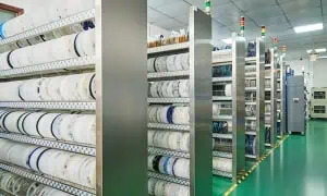
Incoming components and materials
Review identification, storage, shelf-life controls and approved material status.
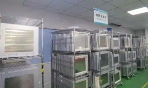
Stencil preparation
Match stencil revision and aperture requirements to the released assembly.
SMT production-line view
Confirm the assigned route and line configuration for the board.
Printing, placement and soldering
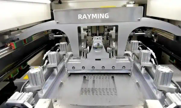
Solder-paste printing
Review stencil setup, paste handling and the agreed deposit-inspection plan.
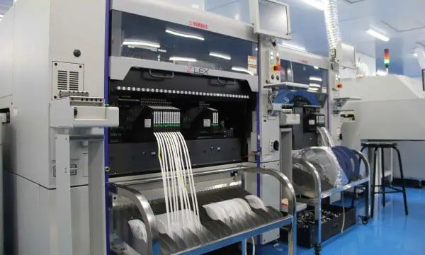
Component placement
Confirm package handling, feeder setup and first-piece checks; no machine-model limit is inferred from this photograph.
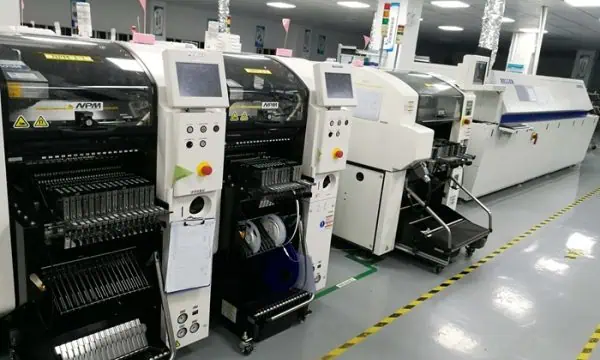
Component placement
Connect the placement program to the approved BOM, orientation and revision.
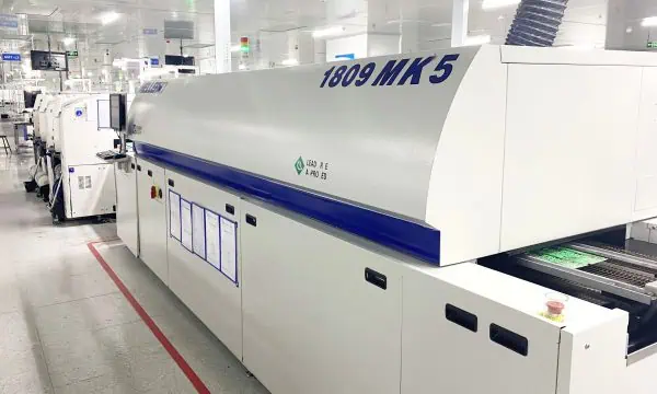
Reflow soldering
Define and validate the thermal profile for the actual board, paste and components.
Inspection, programming and functional verification
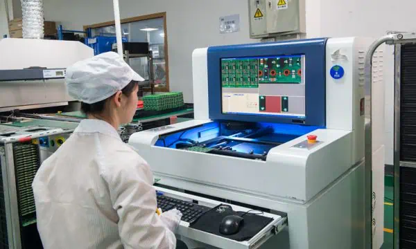
Automated optical inspection
Review visible assembly features against the approved program; hidden joints need an appropriate additional strategy.
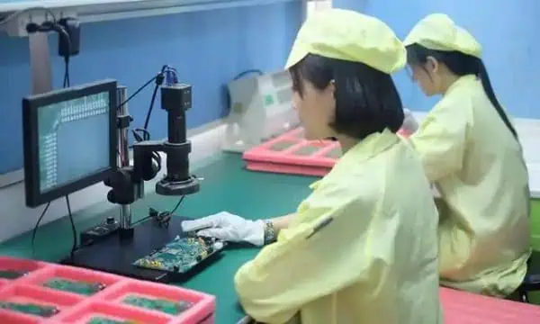
Visual inspection
Apply the agreed acceptance criteria with clear defect disposition.
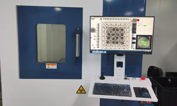
X-ray inspection
Evaluate relevant hidden features using an agreed inspection plan; an image alone does not prove full electrical performance.
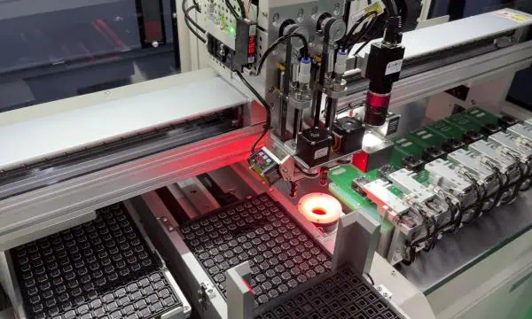
Programming and verification
Control firmware revision, configuration and verification records where programming is ordered.

Functional testing
Agree fixtures, interfaces, limits and a test procedure for the product.
Cleaning, handling and packing
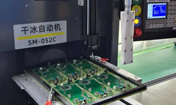
Dry-ice cleaning equipment
Select cleaning requirements from the assembly and contamination risks. A method name is not proof of ionic cleanliness.
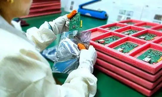
Packing and shipment preparation
Agree protection, identification, handling and accompanying records for the delivered assembly.
Choose inspection and test by the question it must answer
| Method | Question addressed | Important limitation |
|---|---|---|
| Paste inspection, when specified | Was the intended deposit formed before placement? | Confirm the installed method and coverage; do not infer SPI configuration from a printer photograph. |
| AOI / visual inspection | Are the relevant visible assembly features acceptable? | Does not establish hidden-joint quality or complete circuit function. |
| X-ray inspection | What do relevant hidden structural features show? | Does not replace an electrical or functional test. |
| ICT / electrical test, when specified | Are the accessible circuit properties within agreed limits? | Depends on access, fixtures and test-program coverage; equipment availability needs confirmation. |
| FCT | Does the assembly meet the defined operating test? | Only the agreed functions and operating conditions are covered. |
IPC J-STD-001 and IPC-A-610 address soldered-assembly requirements and acceptability. A product-specific test plan remains a separate decision. Continue to PCBA quality control for the inspection workflow.
Follow a mixed-technology board through the line
Consider an illustrative assembly with surface-mount components, one hidden-joint package and a through-hole connector. The useful equipment question is how the board is supported, processed and checked at each stage. A fast placement machine does not by itself solve stencil release, connector access, a difficult thermal mass or missing electrical test points.
Start with the released board dimensions, panel drawing, component packages and assembly sequence. Identify operations that expose the board to another thermal cycle or constrain access to a joint. Then ask how the setup and inspection records follow the same revision. The sequence below explains a review method; it is not a statement that every order follows an identical production route.
| Stage | Question for this example | Evidence or decision |
|---|---|---|
| Print and support | Are stencil revision, board support and paste handling defined? | Released stencil/setup data and the specified deposit-check method. |
| Placement | Do part numbers, orientation and population options match? | BOM/placement reconciliation and setup or first-piece checks. |
| Soldering | Is the thermal process suitable for this board and its components? | Board-specific profile evidence and the applicable process constraints. |
| Connector assembly | Which insertion and soldering route suits access and thermal load? | Agreed assembly method, fixture needs and accessible inspection features. |
| Inspection and verification | Which questions remain hidden or electrically untested? | Defined optical, X-ray, electrical and functional coverage as applicable. |
Read the coverage, not only the station name
For the hidden-joint package, a visible inspection result cannot establish every concealed connection. An X-ray image may address a structural question, while an electrical test addresses a different circuit property. Firmware readback verifies an image or identifier only under its defined procedure; it does not show that every product function passed.
The manufacturer and customer need an agreed combination of methods. A board can pass one check while another is not performed, not accessible or awaiting a fixture. Those states should remain visible in the release record. A percentage without a defined denominator—for example, which joints, nets, units or functions were covered—does not explain the scope.
Example: a release record for one assembly revision
ILLUSTRATIVE TEMPLATE — not a customer record, quotation or factory capability statement.
| Field | Illustrative content to request | Reason |
|---|---|---|
| Assembly identity | Board revision, BOM revision, lot/unit identifier and population option. | Connects the record to the product actually delivered. |
| Setup reference | Placement/inspection program revision and the relevant soldering setup or profile record. | Shows which instructions were used; a generic equipment brochure does not. |
| Test procedure | Procedure and fixture identifiers, firmware version and applicable limits. | Makes the pass/fail result interpretable and repeatable. |
| Result and coverage | Method performed, units or features covered, results and any untested items. | Separates a completed check from an omitted or unavailable test. |
| Exception and release | Rework/deviation reference, required re-verification and authorized disposition. | Prevents an unresolved failure being hidden inside a shipment total. |
No result or customer performance is asserted by this template. Choose the fields relevant to the order and agree the actual report format before production. Keep proprietary test programs, firmware, keys and serial data in the approved sharing channel rather than pasting them into a public planning tool.
Use a supplier review to resolve an actual build constraint
A short example makes the discussion concrete: the enclosure fixes the connector location, but that connector can obstruct access to a nearby joint after insertion. Before accepting the route, compare component sequence, fixture access and inspection timing. The answer may involve a different sequence or tooling; it should be reviewed with the assembly drawing rather than inferred from a photograph of a soldering machine.
For a moisture-sensitive package, the relevant records concern the actual component handling and process conditions. For a board with a large thermal mass, the relevant evidence concerns its soldering profile and acceptance requirements. For a coated assembly, agree whether testing occurs before coating, after coating or both, along with masked regions and required records. The equipment list helps frame these questions but does not replace the product requirements.
Define what the quotation must cover
Identify board fabrication and component sourcing separately from assembly. List any programming, special fixture, inspection report, cleaning, coating or system test that affects the delivered product. Clarify whether the requested quantity is a pilot lot or a repeat release and whether customer-supplied items will be available before the scheduled build.
Ask the response to distinguish included work, optional work and unresolved inputs. A production date remains dependent on the actual file release, material and setup readiness. A report request should state its method and coverage; “test certificate” by itself can mean different things to different teams. Keep these decisions with the approved revision and revise them when the configuration changes.
The evidence worklist below helps you record which categories have been requested, received or reviewed. It is not an audit or supplier rating. No attachment is uploaded, and checking a category does not establish that the document is valid. Download the current summary and attach it manually if it is useful to your enquiry.
RAYPCB ENGINEERING
Manufacturing ProcessSupplier evidence worklist
Loading Supplier evidence worklist…
What to include in an assembly supplier review
Request the process controls relevant to the assembly: component and program revision control, operator competence, ESD and moisture-sensitive material handling, setup verification, profile control, inspection coverage and nonconformance handling.
| Evidence category | Project-specific discussion |
|---|---|
| Production equipment | Model / configuration and process assignment for the planned build. |
| Setup and thermal process | Released assembly data, setup checks and applicable profile evidence. |
| Inspection and test | Program revision, sampling or unit coverage, limits and result traceability. |
| Rework and exceptions | Authorization, handling limits and verification after rework. |
| Release package | Board identity, firmware version where relevant, agreed test results and packing requirements. |
Use quality assurance to prepare certificate and supplier-review questions. For bare-board production, refer to PCB manufacturing equipment. Confirm optional tests and report availability before order release.
Equipment is one part of supplier qualification. Review the EMS capability and evidence checklist alongside the manufacturing program responsibilities.
Start with your project requirements
Send your drawings, revision, order quantities and required acceptance criteria. Include your supplier questionnaire when an audit or onboarding review is required. The applicable manufacturing site, process route, records and commercial scope should be confirmed before order release.
Email opens a draft for you to complete and attach files. The Contact page handles submission; nothing is sent automatically.