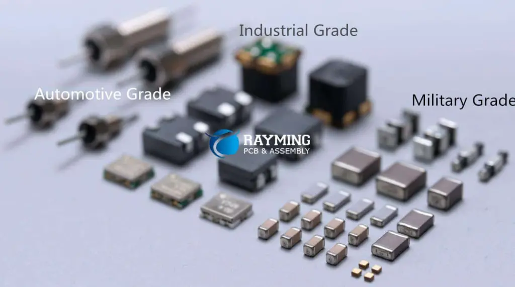


Inductors are passive components that store energy in a magnetic field when current flows through them. They resist changes in current flow.
![]()
![]()
Transistors are active components that can amplify or switch electronic signals. They are fundamental building blocks of modern electronics.

Diodes are semiconductor devices that allow current to flow in one direction while blocking it in the opposite direction.

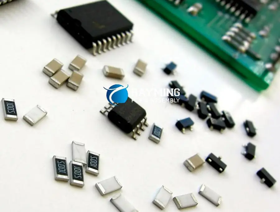
Integrated circuits are complex electronic circuits miniaturized and packaged into a single chip. They can contain thousands or millions of transistors and other components.
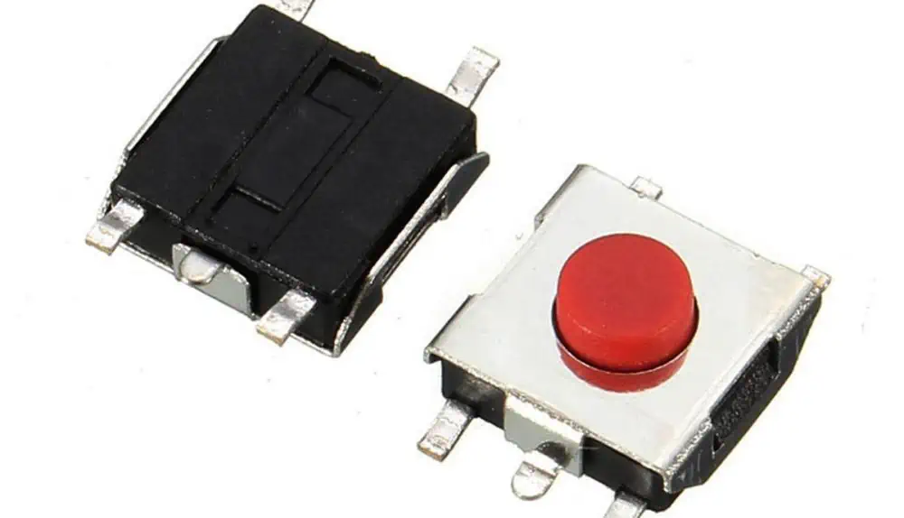
Switches are components used to open or close an electrical circuit, controlling the flow of current.
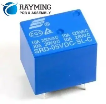
Relays are electrically operated switches that use an electromagnet to mechanically operate a switch.
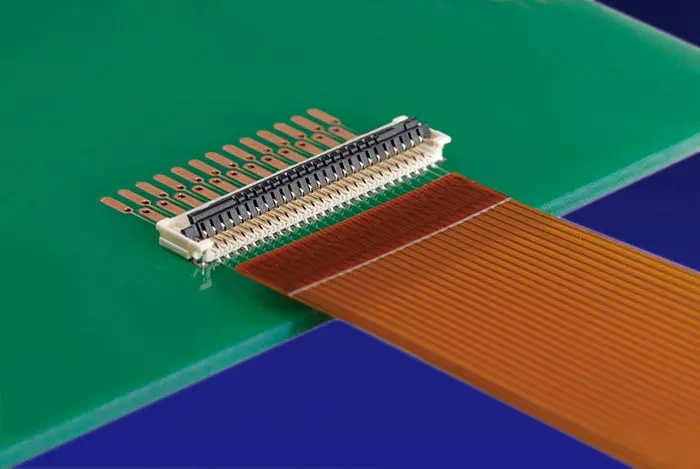
Connectors provide a way to join electrical circuits together, allowing for modular design and easy maintenance.
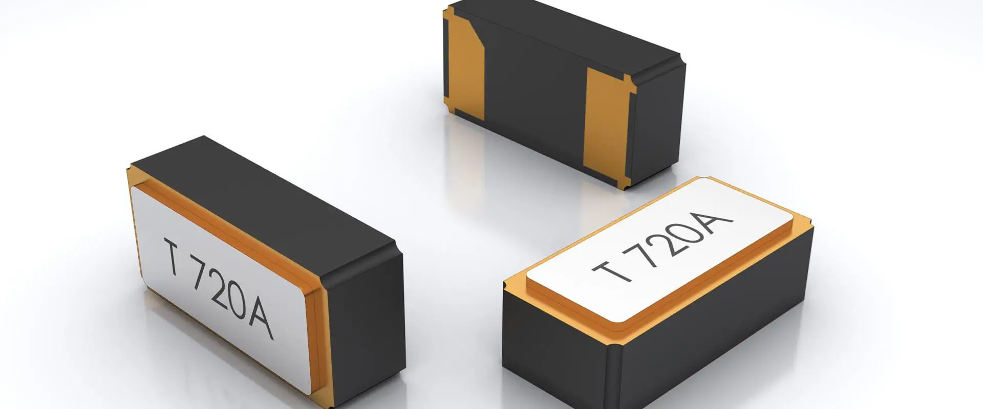
Crystals are used to generate precise frequencies for timing and synchronization in electronic circuits.
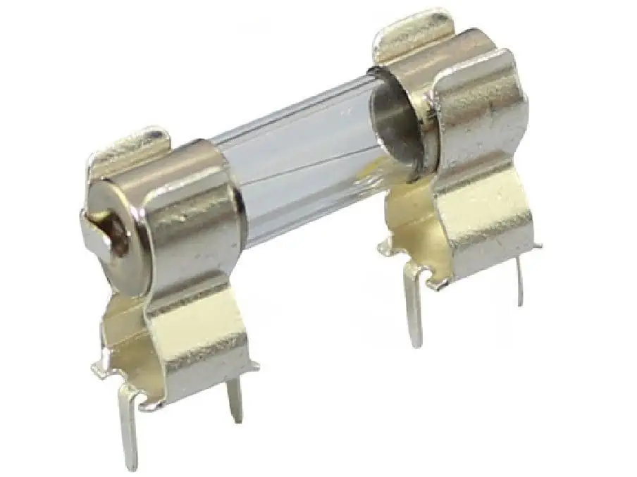
Fuses are safety devices that protect circuits from overcurrent conditions by melting and breaking the circuit when too much current flows.

Microcontrollers are small computers on a single integrated circuit, containing a processor, memory, and programmable input/output peripherals.
Operational amplifiers (op-amps) are high-gain electronic voltage amplifiers with differential inputs and a single output.