High-Quality Flex PCB Assembly: Prototype to Production Solutions

One-stop solution from flexible PCB Manufacturing to flex circuit assembly, Contact us to estimate cost now!

What is Flex PCB Assembly?

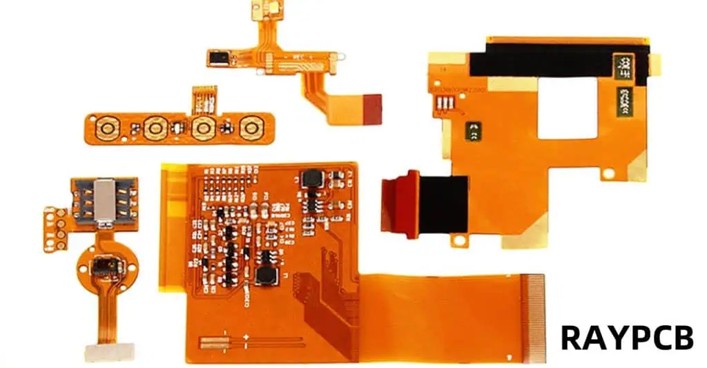
Flex PCB assembly refers to the process of mounting and soldering electronic components onto a flexible printed circuit board (PCB). Unlike rigid PCBs, flex PCBs are made from flexible materials, typically polyimide or polyester, allowing them to bend, fold, and conform to various shapes.

Flex PCB assembly combines the versatility of flexible circuits with the precision of modern electronics manufacturing. This process involves carefully placing components on the flexible substrate and securely attaching them using specialized techniques, ensuring both electrical connectivity and mechanical stability.

Differences Between Flex PCB Assembly and Rigid Assembly

While both flex and rigid PCB assemblies serve the purpose of creating functional electronic circuits, they differ significantly in several aspects:

  1. Substrate Material: Flex PCBs use flexible materials like polyimide, while rigid PCBs typically use FR-4 or other rigid substrates.

  2. Flexibility: As the name suggests, flex PCBs can bend and flex, allowing for dynamic applications, whereas rigid PCBs maintain a fixed shape.

  3. Space Efficiency: Flex PCBs can be folded or bent to fit into compact spaces, making them ideal for applications with spatial constraints.

  4. Weight: Flex PCBs are generally lighter than their rigid counterparts, making them suitable for weight-sensitive applications.

  5. Assembly Techniques: Flex PCB assembly often requires specialized techniques and equipment to handle the flexible nature of the substrate.

  6. Component Placement: Flex PCBs may have limitations on component placement due to bending zones, while rigid PCBs offer more freedom in this aspect.

  7. Cost: Initially, flex PCB assembly can be more expensive due to specialized materials and processes, but it may offer long-term cost savings in certain applications.

  8. Durability: Flex PCBs can withstand repeated bending and flexing, making them more durable in dynamic environments.

Design Considerations for Flex PCB Assembly

Designing for flex PCB assembly requires careful consideration of various factors to ensure optimal performance and reliability. Let’s explore the key design considerations:

1. Placement in Flex PCBs

Component placement is crucial in flex PCB design. Consider the following:

  • Place components in static areas or regions with minimal flexing
  • Avoid placing components near bend lines or fold points
  • Group components with similar heights to simplify assembly

2. Component Type and Size for Flexible Circuits

Choosing the right components is essential for successful flex PCB assembly:

  • Opt for surface mount devices (SMDs) over through-hole components
  • Use smaller, low-profile components when possible
  • Consider flexible components or those designed for flex applications

3. Solder Joint Location

Proper solder joint placement is critical for reliability:

  • Position solder joints away from areas of high stress or frequent bending
  • Use appropriate pad designs to ensure strong solder connections
  • Consider using stiffeners in areas with critical solder joints

4. Flexible Trace Routing

Trace routing in flex PCBs requires special attention:

  • Use curved traces instead of sharp angles to distribute stress
  • Avoid routing traces perpendicular to bend lines
  • Implement wider traces in flex areas to improve durability

5. Stiffeners and Supports

Stiffeners play a crucial role in flex PCB assembly:

  • Use stiffeners in areas with heavy components or connectors
  • Apply stiffeners to regions requiring additional mechanical support
  • Consider partial stiffeners to maintain flexibility in specific areas

6. Prototyping and Testing

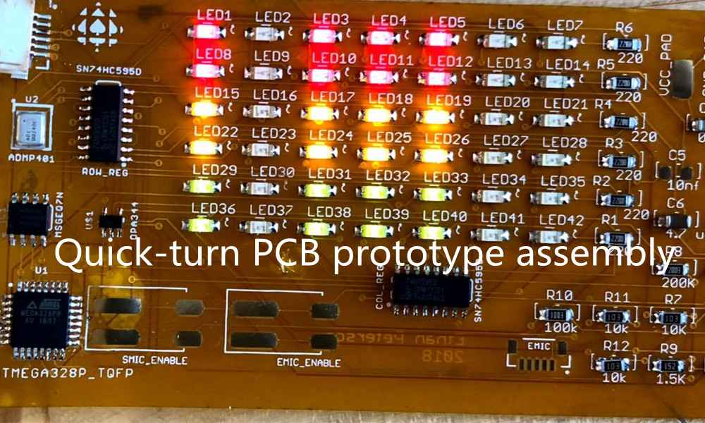
Thorough prototyping and testing are essential:

  • Create multiple prototypes to evaluate different design options
  • Perform extensive bend and flex testing to ensure reliability
  • Use thermal cycling tests to verify solder joint integrity

7. Size

Size considerations in flex PCB assembly include:

(1) Miniaturization

  • Leverage the flexibility to create compact, space-efficient designs
  • Utilize both sides of the flex PCB for increased component density

(2) Package Size

  • Choose component packages suitable for flex applications
  • Consider the impact of package size on overall flexibility

8. Weight

Weight is a significant advantage of flex PCBs:

(1) Lightweight Materials

  • Select ultra-thin flexible substrates to minimize weight
  • Use lightweight copper foils for conductor layers

(2) Low-Profile Components

  • Opt for low-profile or chip-scale package (CSP) components
  • Minimize the use of heavy connectors or mechanical components

9. Mechanical Robustness

Ensuring mechanical robustness is crucial for flex PCB assembly:

  • Design for even stress distribution across the flexible areas
  • Implement strain relief features at transition points between flex and rigid sections
  • Use appropriate materials and thicknesses to achieve the desired flexibility and durability

10. Stress Concentration

Managing stress concentration is vital for longevity:

  • Avoid sharp corners and abrupt transitions in flex areas
  • Use gradual bends and transitions to distribute stress evenly
  • Implement stress relief features such as teardrop pads and rounded corners

11. Impact on Flexibility

Consider the impact of design choices on overall flexibility:

  • Balance component placement and density with desired flex characteristics
  • Use selective stiffening to maintain flexibility in critical areas
  • Design flex regions with appropriate bend radii for the intended application

12. Assembly Challenges

Address potential assembly challenges proactively:

  • Design for ease of handling during the assembly process
  • Consider the impact of flexing on automated pick-and-place operations
  • Implement fiducial marks for accurate component placement

13. Material Compatibility

Ensure compatibility between all materials used:

  • Verify compatibility between flex substrate, solder mask, and components
  • Consider the thermal expansion characteristics of different materials
  • Select adhesives and coatings compatible with flex PCB materials

14. Design Iterations

Embrace an iterative design process:

  • Plan for multiple design iterations to optimize performance
  • Use simulation tools to evaluate design choices before prototyping
  • Incorporate feedback from assembly and testing phases into subsequent iterations

What are Jigs for Flex PCB Assembly?

Jigs play a crucial role in flex PCB assembly, providing support and stability during the manufacturing process. These specialized tools are designed to hold the flexible PCB in place, ensuring accurate component placement and preventing unwanted bending or distortion during assembly.

Key features of jigs for flex PCB assembly include:

  1. Customized Design: Jigs are tailored to the specific layout and dimensions of each flex PCB.
  2. Material Selection: Often made from materials like aluminum or high-temperature plastics to withstand assembly processes.
  3. Registration Pins: Ensure precise alignment of the flex PCB during assembly.
  4. Clamping Mechanisms: Secure the PCB without damaging the flexible substrate.
  5. Heat Resistance: Capable of withstanding high temperatures during soldering processes.
  6. Adaptability: Some jigs are designed to accommodate multiple flex PCB designs for increased versatility.

Tests of Flex Circuit Assemblies

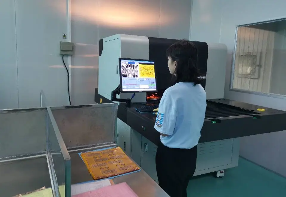
Rigorous testing is essential to ensure the reliability and performance of flex circuit assemblies. Common tests include:

  1. Electrical Continuity Testing: Verifies proper electrical connections.
  2. Bend Testing: Assesses the circuit’s ability to withstand repeated flexing.
  3. Environmental Stress Testing: Evaluates performance under various environmental conditions.
  4. Thermal Cycling: Tests the assembly’s resilience to temperature fluctuations.
  5. Vibration Testing: Ensures durability in high-vibration applications.
  6. Adhesion Testing: Verifies the bond strength between layers and components.
  7. X-ray Inspection: Identifies hidden defects or inconsistencies in solder joints.
  8. Functional Testing: Confirms that the assembled circuit performs as intended.

Flexible Printed Circuit Board Assembly [Step by Step]

Let’s walk through the step-by-step process of flexible printed circuit board assembly:

1. BOM Preparation

  • Create a detailed bill of materials (BOM) listing all components
  • Verify component availability and lead times
  • Ensure all components are compatible with flex PCB assembly

2. FPC Fabrication

  • Manufacture the flexible printed circuit board according to design specifications
  • Perform quality checks on the bare flex PCB

3. Baking Flexible PCBs

  • Bake the flex PCBs to remove moisture and prevent delamination
  • Follow recommended baking times and temperatures for the specific substrate material

4. Fixing Flexible PCB with Jigs

  • Secure the flex PCB in the custom-designed assembly jig
  • Ensure proper alignment and tension to prevent warping or distortion

5. Flexible PCB Assembly

  • Apply solder paste to the PCB using a stencil or dispensing system
  • Place components using automated pick-and-place equipment or manual placement for prototypes
  • Verify component placement and orientation

6. Reflow Soldering

  • Pass the assembled flex PCB through a reflow oven
  • Carefully control temperature profiles to ensure proper solder joint formation without damaging the flexible substrate

7. Thermal Lamination

  • Apply any necessary additional layers or coatings
  • Use thermal lamination processes to bond layers securely

8. Flex PCBA Testing

  • Perform electrical testing to verify connectivity and functionality
  • Conduct mechanical tests to ensure flexibility and durability
  • Carry out any application-specific performance tests

Application of Auxiliary Fixtures in Flexible PCB Assembly

Auxiliary fixtures play a vital role in enhancing the quality and efficiency of flexible PCB assembly, particularly in certain scenarios:

1. Low Density

For low-density flex PCBs:

  • Use simple, cost-effective fixtures to maintain board flatness
  • Implement modular fixtures for quick changeovers between different designs

2. High Quality Requirements

When high precision is crucial:

  • Employ precision-machined fixtures with tight tolerances
  • Utilize optical alignment systems for accurate component placement

3. High Assembly Cost

To optimize costs in high-value assemblies:

  • Design reusable fixtures for recurring production runs
  • Implement automated fixture systems to reduce labor costs and increase throughput

Applications and Innovations in Flexible Circuit Assembly

Flexible PCB Assembly

Flex PCB assembly has found applications across various industries, driving continuous innovation:

  1. Consumer Electronics: Enabling slim, curved designs in smartphones, wearables, and foldable devices.

  2. Automotive: Facilitating complex wiring in tight spaces and supporting advanced driver assistance systems (ADAS).

  3. Medical Devices: Powering miniaturized implantable devices and flexible sensors for patient monitoring.

  4. Aerospace: Providing lightweight, reliable circuitry for aircraft and spacecraft systems.

  5. Industrial Automation: Enabling flexible, dynamic connections in robotic systems and control panels.

Innovations in flex PCB assembly continue to push the boundaries of what’s possible:

  • Stretchable Electronics: Developing circuits that can stretch and conform to complex 3D shapes.
  • Integrated Sensors: Embedding sensors directly into flexible substrates for advanced IoT applications.
  • Biodegradable Flex PCBs: Creating environmentally friendly circuits for disposable electronics.
  • 3D-Printed Flex Circuits: Exploring additive manufacturing techniques for rapid prototyping and customization.
  • Hybrid Rigid-Flex Assemblies: Combining the benefits of both rigid and flexible PCBs in a single assembly.

In conclusion, flex PCB assembly represents a dynamic and rapidly evolving field within electronics manufacturing. By understanding the unique design considerations, leveraging specialized tools and processes, and staying abreast of the latest innovations, engineers and manufacturers can harness the full potential of flexible circuits to create cutting-edge products that meet the demands of today’s technology-driven world.