
RAYPCB · ENGINEERING REFERENCE
Cable Assembly: Types, Terminations & Design Review
Specify the complete interconnect, including cable construction, mating interfaces and the electrical test. Calculate a documented DC voltage-drop budget before release.
Original engineering guidance · References checked September 27, 2026
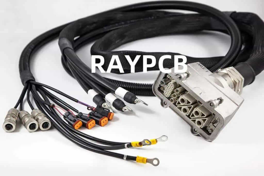
Specify the complete cable assembly, not only the cable
A cable assembly combines a defined cable construction with terminations and any required strain relief, shielding, sealing or identification. It is purchased and tested as an interconnect. Its performance depends on the cable, the transition into each connector and the installed routing. A cable datasheet alone cannot guarantee the behavior of the finished assembly.
For a quotation, identify the cable part number or controlled specification, both connector interfaces, the finished length convention and the test requirements. State whether the assembly carries power, low-frequency signals, high-speed data or RF. These uses lead to different design checks. A connector that mates mechanically does not, by itself, establish impedance, shielding effectiveness or the permitted current.
The useful distinction from a wire harness assembly is the main engineering deliverable. A cable specification emphasizes the cable construction and end transitions; a branched harness adds routing and breakout relationships. Some products contain both. The cable-versus-harness comparison helps define that boundary without forcing an artificial either-or label.
Match cable construction to the electrical task
| Application | Define before sourcing | Verify on the finished assembly |
|---|---|---|
| DC power | Current profile, voltage-drop allocation, environment and fault protection | Path resistance, temperature behavior and connector limits |
| Low-frequency signals | Pin assignment, shielding and ground reference | Correct mapping, noise susceptibility and isolation where specified |
| High-speed differential data | Cable impedance, pair mapping, length and termination geometry | Required channel performance under the applicable interface specification |
| RF or microwave | Reference impedance, frequency range, loss and connector interface | Specified RF measurements with stated reference planes |
| Repeated motion | Cable construction, motion envelope and permitted routing | Qualification for the actual bending or torsion duty |
Use the exact supplier document for conductor resistance, insulation, bend limitations and environmental properties. Do not transfer values between cable families because their jackets look similar. A shield can be foil, braid, a combination or another specified structure; the termination method and coverage continuity matter. Define any drain wire separately from the intended signal return or protective conductor.
For a fixed installation, reserve enough space for the approved bend and connector backshell. For motion, identify the actual cycle, stroke, bend location and torsion. A cable described as flexible for assembly is not automatically qualified for repeated flexing. Agree a candidate construction and validation plan before treating a catalogue description as evidence for the complete machine.
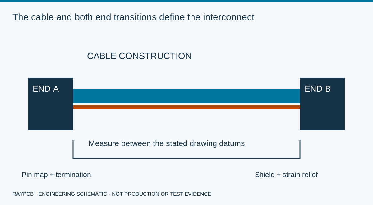
Define the measurement datums and installation access
“One meter long” can refer to exposed jacket length, connector-face-to-face length or total tip-to-tip length. Select one definition and show the measurement points on a drawing. State the tolerance and the condition in which it is measured. The cable path inside a backshell or strain relief can make those definitions materially different.
Check connector key orientation, latch access, cable exit direction and removal clearance in the product. A correct pinout is not useful if the assembly cannot be installed without twisting the cable against its approved routing. Include boots, clamps, grommets and mounting features in the mechanical review. The installation drawing should show where external loads are transferred so they do not act directly on the termination.
For RF measurements, physical end-to-end length and electrical reference planes are different concepts. State which connector interfaces define the measurement and whether adapters or test leads are removed by calibration. For high-speed data, identify the required test or compliance method rather than assuming a DC resistance result verifies the channel.
Calculate a DC voltage-drop allocation
This worksheet evaluates a two-conductor DC supply loop. Enter the outgoing and return lengths independently, the documented resistance per kilometer for each conductor, and the total allowance for series contacts. Values must correspond to the intended conductor temperature. The model does not select wire gauge, estimate bundle heating or approve connector current capacity.
RAYPCB ENGINEERING
EMS InterconnectCable DC voltage-drop worksheet
Loading Cable DC voltage-drop worksheet…
Loop resistance = outgoing length × outgoing resistance per length + return length × return resistance per length + series contact resistance. Multiply by current for voltage drop and by current squared for resistive dissipation. The voltage at the load is the supply voltage minus the calculated drop; the source regulation and transient response are outside this steady-state calculation.
For illustration, two 2 m conductors each specified as 21 ohms/km contribute 0.084 ohm together. Add 20 milliohms for the combined series contacts and the loop becomes 0.104 ohm. At 3 A the calculated drop is 0.312 V and the resistive loss is 0.936 W. With a 24 V source this is 1.3% of the supply. These are hypothetical inputs, not recommended cable specifications.
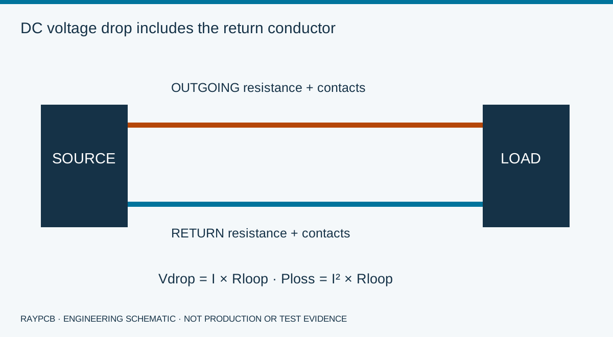
The heat is distributed among wire and contact locations; the total wattage is not a temperature prediction. A small contact resistance can create localized heating. If the calculation produces an impossible negative load voltage, reconsider the stated current and circuit assumptions. For regulated loads, startup, inrush or constant-power behavior, use an appropriate circuit model and verification plan.
Control the transition at both ends
Terminations may be crimped, soldered, insulation-displacement or another approved construction. Select the method from the component and cable specifications. For crimp contacts, the wire range, insulation support and tooling must match the selected parts. Refer to the applicable application specification; a general crimping article cannot provide universal dimensions for every contact system.
For a shielded assembly, define where the shield terminates, what hardware makes that connection and how exposed conductors are supported. A long unshielded transition may change electromagnetic behavior even when every conductor passes continuity. Connector shell bonding and circuit-ground connection are separate design decisions. Resolve them with the system grounding and EMC requirements rather than using the same connection on every cable.
Sealing also depends on interfaces. A cable gland must suit the actual outer diameter and jacket, while a connector seal must suit its mating counterpart and assembly condition. A sealed connector part does not automatically establish the ingress rating of the finished product. Any claimed rating needs evidence for the relevant configuration, including unused positions and installation features.
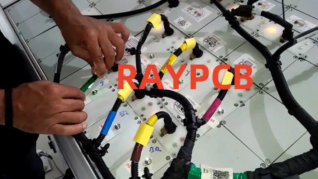
Choose evidence that matches the claimed function
Use a released pin map for continuity and short-circuit testing. Identify which paths should be connected, which must remain isolated, and whether shields or shells form separate groups. Record test limits, fixture version and any required compensation. If the assembly includes filters, resistors or active devices, the test method must account for their behavior.
The IPC/WHMA-A-620 overview describes a workmanship and acceptance framework for cable and harness assemblies. Specify the applicable revision and class in the purchase documents. Compliance with a workmanship framework is not a substitute for the product-specific signal, power, environmental or safety requirements.
For an RF cable, define the frequency range and required loss or reflection measurements. For a data cable, specify the channel requirements and test configuration. For a power cable, establish the resistance and thermal evidence under the relevant load. Do not convert one test result into a broader performance claim. The PCB and assembly test-method guide explains the same coverage principle at board and system level.
Build a transparent cable assembly allowance
Purchased connectors, cable length, terminations, shield treatment, overmolding or other protection, test time and setup all affect cost. A small order may carry a substantial one-time fixture cost. A longer cable increases material use but does not necessarily multiply every labor operation. Separate these categories before comparing suppliers or order quantities.
RAYPCB ENGINEERING
EMS InterconnectInterconnect manufacturing allowance
Loading Interconnect manufacturing allowance…
Use current project quotations for each allowance and identify their source and currency. Material per assembly should include the specified cable length, connectors, contacts and accessories. Labor should represent the agreed assembly operations; testing has a separate per-unit allowance. One-time setup is distributed across the entered order quantity. Do not add a test charge twice when it is already included in a bundled labor quotation.
The worksheet is optional and uncalibrated until you supply those amounts. It excludes freight, taxes, qualification and special tooling unless you explicitly include them in an appropriate category. It cannot establish a delivery promise or resolve an unsupported interface. Direct enquiries can identify missing requirements so the engineering response addresses them before commercial assumptions become fixed.
Release the cable with its installed context
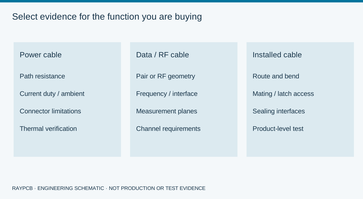
An effective release package connects the electrical table, mechanical drawing, approved BOM and acceptance plan. Include the mating interfaces or their controlled drawings, quantity breaks and expected repeat demand. State whether installation into an enclosure is included. If it is, retain the assembly routing, clamp locations and system-test sequence with the box build scope.
For repeated orders, define how cable, connector and tooling substitutions are approved. Even a nominally equivalent change may affect fit, crimp setup, sealing or signal behavior. Maintain the relationship between the shipped configuration and the test record. Use contract manufacturing when sourcing, integration and ongoing change control are part of a larger OEM program.
Contact RAYPCB with your drawing, part references, cable length and tolerance, pin map and required tests. A preliminary request is welcome with unresolved items clearly listed. Download the current worksheet if useful and attach it manually. The worksheet creates an engineering discussion aid; it does not certify the cable or transfer confidential design files automatically.
Cable assembly questions
Can a cable resistance calculation select the connector?
No. It only estimates the stated DC path loss. Connector selection also requires mating compatibility, contact ratings, environmental conditions, mechanical retention and the manufacturer's application requirements.
Is the shortest possible cable always the best design?
No. Avoid unnecessary length, but retain the installation and service allowance needed for the approved bend, strain relief and removal sequence. Tension at a connector is not a useful way to reduce conductor resistance.
Does a shielded cable automatically pass EMC testing?
No. Shield continuity, termination geometry, grounding, enclosure interfaces and the rest of the system determine the relevant behavior. Validate the complete configuration against its actual requirements.
Prepare a reviewable project request
Send the controlled drawing, component or material references, build quantity and acceptance requirements. Identify open engineering questions and the delivery boundary so the response addresses the actual project.
Send requirements for reviewOptional: attach the downloaded worksheet manually. This guidance does not certify a design, approve a shipment or replace the applicable authorized standards.