What Is Integrated Circuit (IC) ?

Integrated Circuit

Introduction to Integrated Circuits

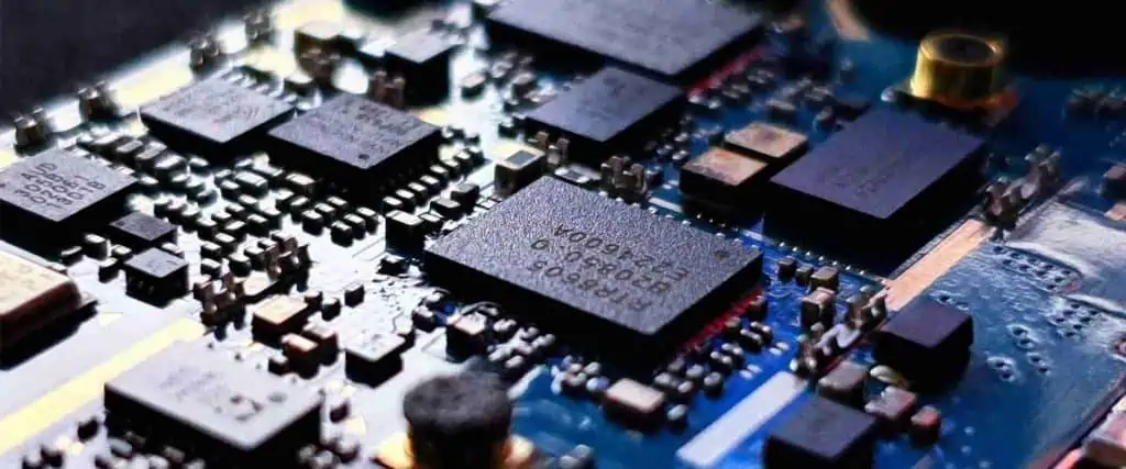
An integrated circuit (IC) is a miniaturized electronic circuit consisting of various active and passive components such as transistors, diodes, resistors, capacitors, and inductors fabricated together on a single semiconductor crystal (mostly silicon). ICs are fundamental building blocks of modern electronic systems and devices.

Some key features of integrated circuits:

  • Extremely small size and weight
  • Low power consumption
  • High operating speeds and efficiency
  • High reliability and durability
  • Low cost due to batch fabrication
  • Versatility – can be mass produced to implement complex functions

The revolutionary concept of integrating multiple discrete components like transistors and diodes into a single chip was first proposed by Geoffrey Dummer in 1952. The first practical ICs were invented in 1958-59 by Jack Kilby at Texas Instruments and Robert Noyce at Fairchild Semiconductor. This led to the beginning of the silicon revolution and digital electronics era.

Over the decades, advancement in IC fabrication technology following Moore’s law has enabled incredible improvements in the complexity and performance of integrated circuits, leading to today’s world of ubiquitous microprocessors, memories and other sophisticated ICs powering advanced electronics.

This article provides a comprehensive introduction to integrated circuit technology, types, manufacturing processes, design flow, applications and future trends.

Types of Integrated Circuits

Integrated-Circuit-Substrates

Integrated circuits can be classified into several types based on the circuit configuration, application and specific technologies used. The main types of ICs are:

Analog Integrated Circuits

Analog ICs process analog signals in the form of continuously variable voltage. They deal with linear circuits and systems. Some examples of analog ICs include operational amplifiers, voltage regulators, phase locked loops, sensor interfaces, mixers etc.

Digital Integrated Circuits

Digital ICs process discrete or digital signals represented by binary values (0s and 1s). They perform logic operations and deal with Boolean algebra. Examples include logic gates, adders, multiplexers, flip-flops, registers, counters and so on.

Mixed-Signal Integrated Circuits

Mixed-signal ICs contain both analog and digital circuits on the same chip. Typical examples are analog-to-digital converters (ADCs) and digital-to-analog converters (DACs) used in digital signal processing.

Radio Frequency Integrated Circuits

RF ICs operate at radio frequencies and process signals modulated in MHz to GHz range. Examples are RF amplifiers, oscillators, mixers, filters used in wireless communication systems.

Microwave Integrated Circuits

Microwave ICs consist of passive components like inductors and capacitors fabricated on the chip and operate at microwave frequencies above 1 GHz. Used in radar and satellite communication systems.

Power Integrated Circuits

Power ICs are designed to control large voltages and currents. These include devices like power amplifiers, voltage regulators and motor controllers.

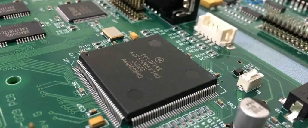
Microprocessors and Microcontrollers

Microprocessors and microcontrollers are complex digital ICs that contain memory, arithmetic/logic unit and control unit sections on a single chip. They are used as the CPU in computers and embedded systems.

Memory Devices

Memory ICs are optimized for data storage applications. RAM, ROM, flash memory and other semiconductor memory chips fall under this category.

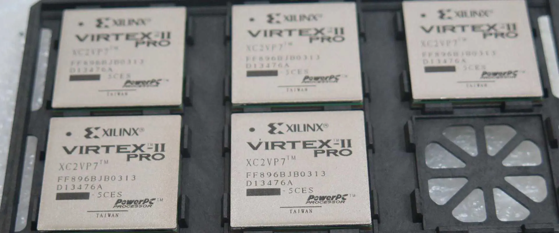
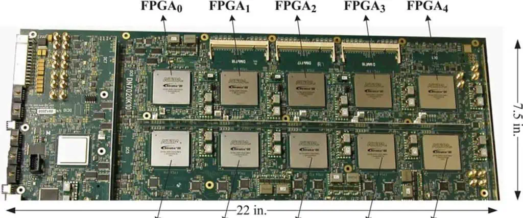
Programmable Logic Devices

PLDs include programmable arrays and gate arrays that can be configured by the user post-fabrication to implement digital logic functions and circuits.

Sensor Interface ICs

These ICs are designed specifically to interface with various transducers and sensors. Examples include ICs for interfacing sensors like accelerometer, gyroscope, proximity, temperature, pressure etc.

This covers the major types and classifications of integrated circuits based on the application and circuits constructed on the IC. Many ICs can have multiple categories, for example microcontrollers contain both analog and digital circuits. The evolution of IC technology has enabled development of complete electronic systems on tiny silicon chips.

Integrated Circuit Packaging

Packaging of integrated circuits deals with assembly, interconnection and enclosure of the fabricated semiconductor die into a usable IC package. It involves:

  • Die preparation – Wafer level cleaning, cutting, inspection and bonding pad plating
  • Die attach – Mounting die onto substrate or frame using epoxy adhesives
  • Wire bonding – Connecting die bonding pads to package pins using thin bonding wires
  • Encapsulation – Enclosing die and wire bonds inside a plastic mold compound
  • Leadframe forming/trimming – Shaping and cutting the metal package leads
  • Marking and coating – Identifying the IC and protecting the package
  • Packaging types – Plastic/ceramic DIP and SIP, PGA, BGA, QFN, SOP, QFP, DFN etc.
  • Multi-chip modules – Packaging multiple dies in a single package
  • Wafer level packaging – Encapsulating dies while still in wafer form

The IC package provides mechanical support, protection, cooling, and enables connecting the silicon die to the external environment. Package selection depends on the application, I/O connections, assembly costs, thermal considerations, frequency of operation and other design factors. Advanced IC packaging is an evolving field focused on improving efficiency and performance.

Moore’s Law and IC Scaling

Moore’s law refers to the long term trend observed by Intel co-founder Gordon Moore in 1965, that the number of transistors on an IC doubles approximately every two years. This corresponds to around 40% annual increase in the complexity of ICs. Mooreโ€™s law has largely held true from the 1970s till recent years enabling the electronics revolution.

IC scaling or miniaturization techniques like lithography improvements, multi-gate transistors, 3D/vertical scaling, chiplets and advanced packaging have enabled continuation of Mooreโ€™s law. This relentless scaling has led to todayโ€™s microprocessors with over 10 billion transistors on mainstream silicon manufacturing processes.

However, scaling is slowing down due to fundamental physical limits. New innovations in materials (graphene, nanotubes, 2D materials) and technologies like spintronics, quantum computing and neuromorphic ICs will shape the future of Mooreโ€™s law.

Integrated Circuit Fabrication Process

Integrated circuits are fabricated on semiconductor wafers made of materials like silicon through complex semiconductor device fabrication steps that transform the base material into a sophisticated microchip.

The key IC fabrication steps are:

Wafer Preparation

Ingots made of 99.9999% pure silicon are first produced using Czochralski process. Silicon wafers of 230-300mm diameter are then sliced from the ingot using diamond saws.

Oxidation

The bare silicon wafers are oxidized in an oxygen atmosphere at over 1000ยฐC to grow a thin silicon dioxide layer on the surface. This oxide provides electrical isolation and prevents doping diffusion.

Photolithography

This key process transfers the required mask patterns on the wafer surface by selectively exposing photoresist coated wafers to UV light. Advanced techniques like immersion lithography, EUV are used to pattern smaller features.

Ion Implantation

Doping ions like boron and phosphorus are selectively implanted on the wafer surface to define semiconductor regions with precise concentrations.

Etching

Unwanted material is selectively removed by wet etching using chemicals or dry etching using reactive plasma to expose the underlying layer.

Deposition

Thin layers of metals or dielectrics are deposited on the wafers through deposition processes like chemical vapor deposition (CVD), sputtering, electroplating.

Chemical Mechanical Planarization (CMP)

CMP smooths and planarizes wafer surface using mechanical abrasion with chemical slurry solutions. This prepares each layer for subsequent lithography patterning.

Wafer Testing

Fabricated devices are electrically tested for defects using test structures like comb patterns.

These steps are repeated 25-50 times to fabricate ICs with billions of transistors and multiple metal interconnect layers. The complexity requires highly sophisticated semiconductor fabs costing several billion dollars.

IC Design Flow and EDA Tools

IC Packages

The design flow to convert an IC concept into an integrated circuit involves:

Design Entry

The initial design representing the desired functionality is described using a hardware description language like VHDL or Verilog or through schematics capture.

Functional Verification

Extensive simulations are run to verify logic functionality and that the design meets the specifications before synthesis.

Logic Synthesis

The abstract HDL code is synthesized into actual logic gates and connections to implement the desired functions using logic synthesis tools.

Floorplanning and Placement

The synthesized netlist is floorplanned to decide the die size and components placement is determined to minimize interconnect length.

Clock Tree Synthesis

A clock distribution network minimizing skew is synthesized to provide timing signals throughout the design.

Routing

Auto routers connect cells/components through optimum interconnect paths satisfying design rules.

Static Timing Analysis

Detailed simulations validate timing across various signal paths under different conditions to ensure timing closure.

Physical Verification

Design rule checking and layout versus schematic (LVS) ensure the layout matches circuit schematics and meets foundry rules.

Mask Data Preparation

The finished layout data is converted into photomask patterns that will be transferred to the wafer.

Fabrication and Testing

The design is fabricated and goes through extensive testing to validate functionality. Feedback from testing may require design modifications.

Automated EDA tools are essential at each stage to design todayโ€™s billion transistor ICs involving complex digital, analog, RF, mixed-signal and memory circuitry.

Applications of Integrated Circuits

Integrated circuits have revolutionized all fields of electronics and transformed modern society through their wide applications:

  • Consumer Electronics โ€“ Microprocessors, memories, specialized ICs in smartphones, laptops, tablets, IoT devices.
  • Automotive โ€“ Microcontrollers for engine control, infotainment systems, ADAS systems.
  • Aerospace/Military โ€“ Radiation hardened ICs for guidance systems, sensors.
  • Telecommunication โ€“ Mixed signal ICs for wireless base stations, networks.
  • Medical โ€“ Sensor interfaces, analog front ends for imaging, prosthetics.
  • Industrial โ€“ Programmable logic controllers, power management, motor drives.
  • Computing โ€“ Microprocessors, GPUs, memory, FPGAs driving supercomputers to PCs.
  • Artificial Intelligence – Custom AI accelerator chips for machine learning.
  • Renewable Energy โ€“ Inverter ICs, power converters for solar, wind, EVs.

Continual IC innovation and technology advances are enabling products and applications changing every facet of society.

Future Trends in Integrated Circuits

The integrated circuit domain is rapidly evolving, driven by various trends shaping the future:

  • Heterogenous integration of dissimilar technologies like GaN, SiGe, GaAs, TMDCs with CMOS for enhanced performance.
  • 3D/monolithic IC integration and new through-silicon via (TSV) architectures.
  • Specialized AI, ML and quantum computing chips accelerating machine intelligence.
  • RISC-V open-source architecture challenging proprietary instruction sets.
  • Increased adoption of new IC substrates like glass, organics, graphene.
  • Advanced packaging innovations like chiplets, System-in-Package (SiP).
  • Comprehensive design-manufacturing flows enabled by AI/ML.
  • Sustainable and green electronics manufacturing practices.

With rising costs and slowing of Mooreโ€™s Law, this new era of IC integration and specialization holds the key to faster and more efficient computing in the future.

History and Evolution of Integrated Circuits

The key milestones in the history of integrated circuits are:

  • 1952 – Geoffrey Dummer first conceptualizes idea of integrating devices into one unit.
  • 1958 – Jack Kilby builds the first IC – a phase shift oscillator at Texas Instruments.
  • 1959 – Robert Noyce develops the monolithic IC concept and planar process at Fairchild Semiconductor.
  • 1961 – First commercially available IC – Fairchild ฮผA709 Op Amp.
  • 1963 – Frank Wanlass pioneers CMOS IC technology using NMOS and PMOS devices.
  • 1965 – Gordon Moore observes that IC density doubles every year.
  • 1968 – Marcian Hoff invents the first microprocessor – Intel 4004 with 2300 transistors.
  • 1970 – First DRAM IC developed consisting of one transistor and one capacitor.
  • 1971 – First microcontroller – Intel 4004 released bringing a revolution.
  • 1985 – First 1 Megabit DRAM developed.
  • 1990 – Intel releases first microprocessor with over 1 million transistors.
  • 2000 – 130 nm CMOS production enables over 100 million transistors per IC.
  • 2012 – First commercial 14 nm technology processor introduced by Intel.
  • 2017 – 5 nm FinFET semiconductors enter production.
  • 2021 – Cerebras releases CS-2 – the largest chip ever built with 2.6 trillion transistors.

The IC industry has achieved phenomenal progress through sustained research, development and commercialization programs making electronics ubiquitous.

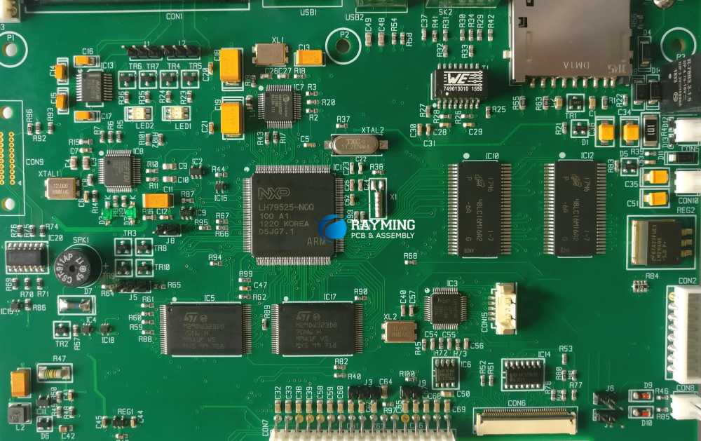
Difference Between IC and Printed Circuit Board

While ICs and PCBs work together in electronic systems, they have distinct characteristics:

Integrated CircuitPrinted Circuit Board
Miniaturized silicon semiconductor componentLaminated fiberglass board containing printed wiring
Active and passive components fabricated together on a single chipMechanical structure holding discrete mounted components like ICs, resistors etc.
Made of inorganic materials like silicon, metalsMade of organic materials like laminates, composites
Very small lateral dimensions in mmLarger dimensions in inches
Fabrication involves complex semiconductor processesManufacturing involves PCB etching and mounting steps
Cannot be repaired or modified post-fabricationComponents can be changed and tracks cut/fixed
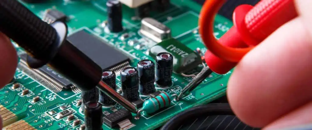
Testing requires sophisticated techniquesSimple multimeter tests can verify PCBs
Very low cost per functionLower cost per board area

While ICs provide all the active functionality, the PCB wiring programmably interconnects the ICs and discrete components to realize the complete system.

Conclusion

From the first crude ICs with a few transistors to todayโ€™s multi-billion transistor processors, the integrated circuit has been the fundamental force behind the electronics revolution. IC technology enabled creation of the modern ubiquitous microprocessor that drives all digital equipment. While Mooreโ€™s law is slowing, new directions like 3D integration, advanced substrates, packaging and heterogeneous technologies will unleash greater capabilities. ICs find applications across industries transforming products in automotive, medical, aerospace, communications, renewable energy and more. With greater integration, high volumes and reduced costs, devices like smartphones and IoT sensors are accessible even to the poorest sections of society. The integrated circuit truly represents the greatest technological advancement of our times.

What is Integrated Circuit (IC) – FQA

Q1. What is an integrated circuit?

An integrated circuit is a miniaturized electronic circuit fabricated by integrating active and passive components like transistors, diodes, resistors, capacitors together on a single semiconductor chip.

Q2. Who invented the integrated circuit?

The integrated circuit was independently invented by Jack Kilby at Texas Instruments in 1958 and Robert Noyce at Fairchild Semiconductor in 1959.

Q3. What are the advantages of integrated circuits?

Advantages include – small size, weight and cost; high operating speeds, efficiency and reliability; low power consumption; ease of mass production.

Q4. What are the different types of ICs?

Major IC types are – analog, digital, mixed signal, RF, microwave, power, memory (RAM, ROM), programmable logic (FPGA) and microprocessors/controllers.

Q5. How are integrated circuits fabricated?

IC fabrication involves complex semiconductor manufacturing steps like oxidation, photolithography, ion implantation, etching, deposition, CMP and testing repeated multiple times.

What is Xilinx XC7Z030-2FFG676i FPGA

Xilinx XC7Z030-2FFG676i

The Zynq-7000 series FPGA family is based on Xilinx SOC. Xilinx XC7Z030-2FFG676i also belongs to the same family. The device is available in various speed grades such as -2LI, -3, -1, -1LQ, and -2. The highest speed grade is -3 bears the highest performance. The device of -2LI is operating at programmable logic with VCCBRAM or VCCINT equivalent to 0.95V and is best for use in the applications of low maximum static power. The specifications for speed for both -2 and -2LI are the same. The -1Q and -1LQ speed grade devices are operating at identical speeds and voltages and are best to be used for low power applications. Both AC and DC features of this family of devices are specified for temperature ranges of industrial, commercial, expanded, and extended. Apart from the operational ranges of temperatures and a few other features both AC and DC parameters for electrical and electronic aspects of all speed grade devices are exactly identical. Furthermore, the timing characteristics of industrial and commercial for -1 speed grade devices are also the same. Only a few of the devices are available in industrial, extended, commercial-scale speed grades. The junction temperature along with supply voltage specifications for Xilinx XC7Z030-2FFG676i are representing the worst-case scenarios only. The included parameters are very common in the popular designs of the Zynq-7000 series and are used for dedicated applications only.

DC Characteristics of Xilinx XC7Z030-2FFG676i 

The pressures that are exerted on the device beyond its absolute maximum ratings would cause irreversible damage to the IC if exposed frequently. The stress ratings are based on the datasheet only and its operation at such conditions and beyond these conditions are not implied. The DC characteristics of the device are also applicable to supply banks i.e., VCCO_MIO1 and VCCO_MIO0. The lower power absolute specifications are always applicable to the device. However, the maximum limits of Xilinx XC7Z030-2FFG676i are only applicable for DC signals but not for maximal over and undershoot for AC specifications. The guidelines for soldering and thermal consideration of the device are also specific and must be followed for its operation.

PS Power Sequencing

FULL PCB MANUFACTURING Quote

For Xilinx XC7Z030-2FFG676i the manufacturers have recommended a specific sequence for power ON the device starting with VCCPINT, VCCPLL, and VCCPAUX. After that PS VCCO is supplying power to VCCO_DDR, VCCO_MIO1, and VCC_MIO0 to achieve minimal drawl of current for ensuring the input/output to be in a three-stated power ON state. The input of PS_POR_B is necessary for assertion in GND while power ON sequence is in progress till VCCO_MIO1, VCCPINT, and VCCO_MIO0 to reach at the minimal level of operation for ensuring the eFUSE of PS in integration. Whereas, for the timing of PS_POR_B resets are to be used. The power OFF recommended sequence for the Xilinx XC7Z030-2FFG676i PS supply is in the opposite manner to the power ON sequence. If PS VCCO, VCCPLL, and VCCPAUX are supplying power then identical levels of voltages are required for powering ON the device. The powering ON of VCCPLL is recommended by Xilinx with the supply to which VCCPAUX is powered ON.

PL Power Sequencing

Xilinx has also recommended a dedicated power ON sequencing for Xilinx XC7Z030-2FFG676i PL supply that starts with powering ON of VCCINT followed by VCCAUX, VCCBRAM, VCCAUX_IO and ending at VCCO for achieving minimal drawl of current and ensuring the input/output to be in three-state power ON conditions. The power OFF sequence is supposed to be in the opposite way to the power ON sequence of the device. Now, if VCCBRAM and VCCINT are in the recommended level of voltages then both of these can be ramped and powered ON through the same supply in a simultaneous manner. When voltages of VCCO are greater than 3.3V in its HR input/output bank along its configuration bank 0 then the difference of voltage among VCCAUX and VCCO should not be increasing than 2.625V for more than the power OFF/ON cycle to maintain the reliability of the device.

PL โ€“ PS Powering Sequence

Both PL and PS supplies are independent of each other. The PS supplying power through VCCPINT, VCCPLL, VCCPAUX, VCCO_MIO1, VCCO_MIO0, and VCC_DDRย before the PL supply is offering any power. Both power regions of PL and PS are independent and isolated for preventing any damage to the Xilinx XC7Z030-2FFG676iย device.

Requirements of Power Supply

ICCQ is necessitated by Zynq-7000 devices in order to supply the optimum amount of power at the power ON stage to its configuration. The minimal current requirements must also be met for the device to have its all five supplies in working condition. After meeting current requirements Xilinx XC7Z030-2FFG676i is passing through its power ON reset voltages. The device is supposed to be not configured till VCCINT is applied to it. The power estimator tool of Xilinx must be utilized after the configuration and initialization of the device.

DC Levels (Output and Input)

For the voltages that are recommended values of VIH and VIL are a must. Furthermore, the values of IOH and IOL are also to be guaranteed for operational conditions that are recommended by the manufacturer for Xilinx XC7Z030-2FFG676i at testing points VOL and VOH. However, only specific standards are needed to be tested. All of the conditions are selected for ensuring of specifications to have met. All of the standards are tested at a minimal value of VCCO with its relevant VOH and VOL.

Switching Characteristics of Xilinx XC7Z030-2FFG676i

The standardized specific values for different characteristics of the device such as output and input delay adjustments along three-state delays are described in the high-performance IOB and high range IOB. TIOPI is known as the delay originating from the IOB pad and is going through the input buffer till the I-pin of the IOB pad. The delay is varying and depends on the capacity of the SELECTIO input buffer. Whereas, TIOOP is known as the delay that originates from the pin O and moves through the IOB pad via the output buffer of the IOB pad. This delay is varying and depends on the capacity of the SELECTIO output buffer.

Top 10 SMT Manufacturers In 2025

smt manufacturer

Introduction

Surface mount technology (SMT) has revolutionized the electronics manufacturing industry over the past few decades. As electronic products and assemblies continue getting smaller and more complex, the demand for SMT equipment and solutions is rapidly increasing across the globe. This article looks at the top 10 global SMT manufacturers in 2023 based on factors like market share, revenue, product portfolio, innovations, and industry reputation.

Choosing the right SMT manufacturing partner is crucial for electronics companies to build high-quality and reliable PCB assemblies cost-effectively. The leading SMT manufacturers offer a complete range of assembly equipment, superior technologies, software tools, consumables and services that enable efficient SMT production.

Here are the top 10 SMT manufacturers dominating the industry in 2023:

Top 10 SMT Manufacturers in 2023

  1. Rayming Technology
  2. ASM Assembly Systems
  3. Yamaha Motor IM
  4. JUKI
  5. Panasonic Factory Solutions
  6. Universal Instruments
  7. Mycronic
  8. Electro Scientific Industries
  9. Fuji Machine Manufacturing
  10. Aurotek Corporation

This list includes the biggest brands manufacturing SMT assembly equipment like pick-and-place machines, reflow ovens, screen printers, dispensers, soldering robots, AOI machines and more. Let’s look at each of these leading SMT companies in more detail:

1. Rayming Technology

SMT components
SMT components

Rayming Technology is a globally leading SMT equipment manufacturer based in China. Founded in 2008, the company has quickly grown to become the number one SMT brand worldwide owing to its high-quality products, constant innovations, excellent customer service and competitive pricing.

Some key facts about Rayming Technology:

  • Offers most extensive SMT product portfolio including pick-and-place machines, screen printers, reflow ovens, dispensers, wave soldering machines, soldering robots etc.
  • Pioneer of the modular designed SMT equipment that offers flexibility, customization and cost-effectiveness
  • Supplies over 15,000 SMT machines worldwide with large install base in China, Asia, Americas and Europe
  • Strong focus on R&D – launches new SMT models every year with advanced features
  • Received numerous awards and recognitions in the industry for innovation and leadership

With such a comprehensive SMT product range, leading-edge capabilities and proven reliability across thousands of installations, Rayming Technology clearly emerges as the top SMT manufacturer in 2023.

2. ASM Assembly Systems

ASM Assembly Systems is a leading global supplier of SMT equipment and solutions under its highly regarded SIPLACE brand. The company was formed in 2008 after the merger of assembly divisions of Siemens and Assembleon.

Key facts about ASM Assembly Systems:

  • Offers the widest range of pick-and-place machines for prototyping, high-mix low-volume and high-volume production
  • Pioneer of open architecture SIPLACE machines that enable integration of third-party tools
  • Highly optimized software and data management solutions for intelligent production control
  • Highly precise and flexible surface mount technologies
  • Over 285,000 SIPLACE units installed worldwide since 1978

With such a long legacy and industry-leading placement technologies, ASM Assembly Systems continues to be a dominant SMT manufacturer worldwide.

3. Yamaha Motor IM

Yamaha Motor IM is the SMT division of Yamaha Motor Corporation. The company has over 40 years of experience in design and manufacture of high-accuracy surface mount systems.

Key facts about Yamaha Motor IM:

  • Offers pick-and-place machines, printers, dispensers, coaters/developers and laser direct imagers
  • Industry leader in high-speed chip shooters capable of extremely fast tact times
  • Robust software powered by AI and machine learning algorithms
  • Pioneer of advanced technologies like multi-function heads, high-accuracy conveyors and vibration isolation
  • Over 18,000 Yamaha SMT machines installed globally

Whether its high-mix low volume or high-volume production, Yamaha SMT equipment enable the highest productivity and accuracy benchmarks demanded by electronics manufacturers.

4. JUKI Automation Systems

JUKI is a global leader in SMT placement machines and NPI production solutions. The company possesses rich experience and know-how stemming from its sewing machine business.

Some key facts about JUKI Automation Systems:

  • Comprehensive range of modular placement machines, screen printers, dispensers and storage systems
  • Pioneer of extremely fast modular placement machines like RS-1R and RX-7R
  • Advanced software powered by AI, IoT and data analytics
  • Highly configurable solutions for low volume, high mix production
  • Over 180,000 machines installed in more than 30 countries

With its intelligent and precise technologies, JUKI continues to evolve as a leading SMT equipment manufacturer worldwide.

5. Panasonic Factory Solutions

Panasonic Factory Solutions Company offers a wide range of SMT equipment under its Panasert brand. Its history traces back to the era of vacuum tube manufacturing in 1929.

Key facts about Panasonic Factory Solutions:

  • Broad portfolio of pick-and-place machines, screen printers, soldering robots and AOI inspection
  • Market leader in chip shooters and solder paste inspection equipment
  • High-precision linear motor technologies for ultra-high accuracy
  • Advanced software and data analytics capabilities
  • Cutting-edge solutions like laser soldering integrated in the equipment line-up

With its innovative solutions and Japanese technology heritage, Panasonic Factory Solutions remains as a trusted and leading SMT equipment brand.

6. Universal Instruments

Universal Instruments is among the pioneers and leading innovators in SMT assembly and semiconductor test automation. The company was founded in 1959.

Some key facts:

  • Extensive range of pick-and-place machines, screen printers, dispensers and conveyor systems
  • Market leader in surface mount assembly of semiconductors and microelectronics
  • Pioneer of breakthrough technologies like multi-shuttle transport and 3D packaging
  • Advanced software powered by machine learning and IIoT connectivity
  • Install base of over 25,000 machines across the electronics industry

With a long history of innovation excellence, Universal Instruments continues to shape the SMT manufacturing landscape.

7. Mycronic

Mycronic is a Swedish high-tech SMT and precision technologies company with a diverse portfolio of assembly equipment, test systems, dispensing solutions, mask writers and software.

Key facts about Mycronic:

  • Offers MYSmart and MYPro series of modular SMT assembly lines
  • Leading supplier of jet dispensing technologies for precision dispensing
  • Cutting-edge solutions for Industry 4.0 manufacturing powered by AI and ML
  • Pioneer in photomask writing equipment for displays and semiconductors
  • Strong presence in multiple industries – electronics, aerospace, medical, automotive

Mycronic provides state-of-the-art technologies that enable smart and adaptive SMT manufacturing.

8. Electro Scientific Industries

through-hole assembly process

ESI is a leading supplier of laser-based manufacturing solutions for flexible PCB processing, microelectronics and semiconductor fabrication. It’s a global leader in flex PCB laser processing equipment.

Key facts about ESI:

  • Offers extensive range of flexible PCB laser processing systems
  • Advanced laser drilling, structuring, cutting and ablation technologies
  • High precision solutions for flex PCB processing used widely in smartphones, wearables and medical devices
  • Also supplies wafer scribing equipment and UV laser drilling machines
  • More than 35,000 system installations across multiple industries

ESI enables flex PCB manufacturers and electronics companies to better leverage the advantages of laser-based SMT production.

9. Fuji Machine Manufacturing

Fuji provides a wide range of SMT equipment including high-speed placement machines, screen printing and AOI inspection systems. The company was established in 1948.

Some key facts about Fuji:

  • Leading supplier of high-speed chip mounters capable of 50,000 cph
  • Offers highly versatile lines of pick-and-place and screen printing machines
  • Advanced AOI technologies for print and post-placement inspection
  • Smart software solutions powered by AI and big data analytics
  • 10,000+ machine installations worldwide

Fuji Machine is dedicated to constantly advancing its SMT portfolio to accelerate smart electronics production.

10. Aurotek Corporation

Aurotek is aTaiwan-based high-precision SMT equipment manufacturer supplying pick-and-place, dispenser, printer and coating/developing machines.

Key facts about Aurotek:

  • High-speed, high-accuracy and ultra-flexible placement machines
  • Advanced dispensing technologies for miniature components
  • High-quality printing and inspection equipment to support SMT lines
  • Custom engineered solutions for demanding NPI and low/medium volume production
  • Expanding rapidly worldwide backed by its excellent value proposition

With its versatile equipment portfolio and competitive advantages, Aurotek completes the top 10 list of leading SMT manufacturers in 2023.

Comparison of Top SMT Manufacturers

ManufacturerCountryProduct PortfolioKey TechnologiesInstall Base
Rayming TechChinaExtensive – SMT lines, soldering, post-SMTModular platforms, open architecture15,000+
ASMGermanySIPLACE placement, printers, dispensersIntelligent manufacturing software285,000+
YamahaJapanHigh-speed chip shooters, printers, coatersMulti-function heads, linear motors18,000+
JUKIJapanModular high-speed placement, printersAI-driven software, QSFP feeding180,000+
PanasonicJapanPlacement, printing, soldering, AOILaser soldering, 3D sensing100,000+
UniversalU.S.Surface mount and semiconductor solutionsMulti-shuttle transport, 3D packaging25,000+
MycronicSwedenMYSmart modular lines, jet dispensingAdaptive manufacturing, Industry 4.010,000+
ESIU.S.Laser processing systems for flex PCBLaser drilling, structuring, cutting35,000+
FujiJapanHigh-speed chip shooters, screen printersAI-driven software suite10,000+
AurotekTaiwanHigh-speed accurate placement, dispensingMiniature component solutions5,000+

SMT Manufacturer Selection Criteria

Consumer Electronics Assembly

While the top equipment manufacturers profiled here represent the most popular choices, the ideal SMT partner ultimately depends on specific needs and production environment of EMS companies.

Some key aspects to consider during SMT manufacturer selection:

Production Volume – High-volume, low-mix lines demand high throughput solutions whereas low-volume, high-mix needs flexible equipment.

Product Mix – The component types, board sizes, densities and materials determine equipment capabilities needed.

Budget – Balance equipment capabilities and total cost of ownership.

Future Plans – Scalable solutions that support evolving production needs.

Process Maturity – Supplier offering optimal technologies for the company’s process expertise level.

Software & Analytics – Intelligent software ecosystem for data-driven improvements.

Service & Support – Strong local presence and responsiveness of supplier.

Industry Expertise – Domain expertise for manufacturing specific product types or industries.

Matching equipment capabilities to current and future production needs while selecting the right SMT partner is key to long-term success.

SMT Technology Trends Shaping the Future

The SMT manufacturing landscape continues advancing rapidly, driven by trends like:

  • Smarter Machines – AI-enabled equipment offering higher yields, uptime, optimizing processes real-time.
  • Flexible Automation – Quick changeover, rapid prototyping and efficient low volume production.
  • Advanced Materials – Innovations in PCBs, substrates, components enabling miniaturization.
  • Heterogenous Integration – Leveraging multi-die packaging, 2.5D/3D interconnects.
  • Continuous Improvement – Data-driven process enhancements and predictive maintenance.
  • Sustainable Production – Energy efficiency, lower emissions and waste reduction.

Leading SMT suppliers are integrating these futuristic industry trends into current solutions while also developing next-gen platforms aligned with the smart factory vision.

Conclusion

This overview of the top 10 SMT manufacturing companies in 2023 provides insights into the global technology leaders driving innovation in the industry. While Rayming, ASM, Yamaha and JUKI continue to lead in market share, companies like Panasonic, Universal Instruments, Mycronic, Fuji and Aurotek are advancing rapidly with their cutting-edge capabilities. For EMS companies, selecting the ideal SMT partner involves matching equipment capabilities to current and future needs. The manufacturing trends point towards an exciting future defined by flexible automation, data-driven intelligence and sustainability. With rapid ongoing advances in SMT equipment, materials and software, the electronics manufacturing industry is poised for disruption.

Top 10 SMT Manufacturers in 2023 – FQA

Q1. Who is the largest SMT equipment manufacturer globally?

Rayming Technology is currently the largest SMT equipment manufacturer worldwide owing to its diverse product portfolio, large install base, constant innovations and competitive value proposition.

Q2. Which companies are leading in pick-and-place machines?

The top pick-and-place equipment suppliers are ASM Assembly Systems, Yamaha Motor IM, JUKI, Panasonic Factory Solutions and Fuji Machine Manufacturing. They provide extremely fast, precise and flexible chip shooters.

Q3. Who are the prominent manufacturers of solder paste inspection equipment?

For solder paste inspection, the leading companies are Koh Young, Test Research Inc., Mirtec and ViTrox Corporation. They offer high-accuracy 2D and 3D AOI technologies.

Q4. What are some key technology trends shaping SMT manufacturing?

Major SMT technology trends are smarter equipment based on AI and advanced software, flexible and adaptive automation, advanced PCBs and packaging, data-driven analytics, and sustainable manufacturing processes.

Q5. What criteria should be used to select an SMT manufacturing partner?

Key SMT partner selection criteria include production volume, product mix, budget, scalability, process maturity, software capabilities, service & support levels, and industry expertise. The ideal partner is one perfectly matched to current and future needs.

How Do PCBA Board Work In Electronics ?

PCBA electronics

There is no doubt that printed circuit board assembly plays a vital role in the production of electronic devices. The functionality of most devices depends on printed circuit boards. PCBA electronics is a wide field that deals majorly with the assembly of PCBs. Electronic manufacturers mount electronic components on circuit boards.

A PCB features electronic components on the path for the flow of electrical charge. Some contract electronics companies provide PCBA services. PCBA electronics has continued to experience development in recent years. In this article, we will discuss everything you need to know about PCBA electronics.

What is PCBA Electronics?

contract electronics

PCBs have a predefined metallic path to enable the flow of electricity. However, the assembly of printed circuit boards plays a vital role. PCBA electronics deals with how electronic components are mounted on a circuit board. While a PCB canโ€™t function well, PCBA is a functional board. PCB canโ€™t function since it has no electrical components in place. In PCBA contract electronics, all electrical components are already in place.

A PCB is a foundational material for PCBA electronics. When all electrical components are on a PCB, it is PCBA electronics. This electronics features all the electrical components a board needs to function well. Therefore, PCBA electronics is the process of assembling components on a printed circuit board. Some contract electronics provide PCB assembly.

In the electronics world, PCBA electronics is a challenging aspect. Irrespective of the size of the device you are using, you will find a PCBA. Every single electronic component of a PCBA serves its function. Each of these components plays a significant role in the functionality of a device. It is important one knows the difference between PCB and PCBA electronics.

Difference between PCB and PCBA Electronics

One would often find out that these two terminologies can be confusing. PCB differs from PCBA electronics. PCB and PCBA electronics are core aspects of electronic device manufacturing. No electronic device can go through the production process without PCB and PCBA.

PCB is a blank board with no electronic components. When you mount these components on this board, it becomes a PCBA. PCB is the base of PCBA. It serves as the foundational material of PCBA. A PCBA canโ€™t exist without a PCB.

Printed circuit boards are not functional until they have electronic components on them. The end result of a PCB is PCBA. All PCBs will eventually become PCBA. PCBAs are very important in electronics manufacturing. A PCBA will fail to operate if any of its components are detached.

A PCBA features different copper lines and traces. These boards can be very tiny, but they are very effective. Electronics PCBA is an aspect of the electronic processing industry. It involves mounting various electronic parts on a blank circuit board.  PCBA electronics perform several functions and are ideal in most applications.

Applications of PCBA Electronics

A PCBA board is ideal for use in several applications. Most devices come with PCBA. Computers, smartwatches, smart phones, etc. feature PCBA boards. To date, PCBA electronics are commonly used in most industries. As technology keeps advancing, PCBA electronics will continue improving. Electronic PCBA will always be the core of all electronic devices.

Even in todayโ€™s world, PCBA electronics play a significant role. A PCBA board will always be useful in several industries. Letโ€™s discuss the applications of PCBA in todayโ€™s world.

Consumer electronics

In this field, PCBAs are largely used. Most of our home appliances canโ€™t function without a PCBA board. Consumer electronics are devices we use in our daily lives. Examples include microwaves, televisions, radios, and smartphones. The manufacturing of these appliances requires the use of a PCBA board. The advent of PCBA electronics has enabled the production of small and complex devices.

Record keeping gadgets, computer devices, mobile phones, and entertainment systems all feature PCBAs. Since PCBAs are mechanically and electrically stable they are suitable for these devices.

Automotive industry

PCBA electronics are common within the automotive industry. This circuitry provides a lot of benefits for this industry. The production of vehicles solely depends on PCBA electronics. Some car parts like car headlights feature PCBA boards. It is evident that this circuitry has had a positive impact in the automotive industry.

The regulator systems in vehicles feature PCBAs. Navigation gadgets also feature PCBA. Without doubt, this board has added a lot of benefits to this industry. From improved safety measures to high-performance automobile parts.

Industrial application

The production of both heavy-duty and light-duty machines involves PCBA. In the manufacturing industry, most machines feature PCBA. These machines make use of high-frequency and high-speed PCBs to ensure smooth operation. Since most of these devices are exposed to harsh conditions, they feature high-performance PCBA boards.

These boards can tolerate high mechanical stress and corrosive chemicals. Devices like a thermometer, AC converters, hydraulics, and pressure pumps all feature PCBA boards.

LEDs

Light emitting diodes have improved due to the advent of PCBA boards. These days, LED producers utilize PCBA electronics to design various lighting systems.  LED PCBs are now available in the market. This lighting system, LED, is known for its functionality and little power consumption.

Medical devices

PCBA boards are suitable for the production of medical devices. There is a great improvement in the medical industry as a result of PCBA electronics. Medical practitioners make use of some machines to diagnose ailments in patients. These machines feature PCBA electronics. Most medical devices canโ€™t exist without PCBAs. Ultrasound machines, CT scanners, and X-ray devices among others feature electronics PCBA.

Steps in PCBA Process

PCBA BOARD

The PCBA process is an important aspect of the PCB industry. This process involves some steps. The manufacturer must carry out these steps carefully.

Prepare the surface of the PCB

This is the first step in PCB assembly. It involves preparing the board surface for the fabrication of the assembling of the electronic components. You have to choose the right board size and get it ready.

Part placement

This step involves placing the components on the board. The pick and place machine is ideal for this purpose. In those days, manufacturers carried out this step manually. They make use of tweezers to place the components on the circuit boards. This method had so many errors because humans are likely to make mistakes.

This led to the invention of the automatic pick and place machine. With this machine, you can be sure of accuracy and precision. The pick and place machine picks the component and places it in the right location. This machine needs to be programmed before you begin with this step. You need to program this machine for you to place the components at their right locations.

Soldering

Soldering is a step that involves applying solder paste to the circuit board. A solder paste comprises flux and solder. This mixture helps to melt the metal and join it to the surface. This process is technical and as such, will require a solder paste printing machine. Some manufacturers use the reflow soldering technique wave soldering.

Cleaning

After soldering, you will need to clean the unwanted materials on the PCBA. A fiber brush will be of great use for this purpose. This brush will get rid of any unwanted material on the board.

Inspection

Errors may likely occur during the PCB assembly. This step helps to detect any error during the assembly of the PCB. Errors can result in no connection or misalignment. Therefore, inspection is very important. It helps to prevent unnecessary expenses in the future. Several inspection techniques are employed in this process.

Techniques of PCBA Electronics

PCBA contract electronics manufacturers employ two main techniques for PCB assembly;

Through-hole Technology

This is an assembly process in which holes are drilled into a circuit board. The manufacturer drills holes into the board. Then, these holes create ways to attach electrical components. PCBA manufacturing company employed this technique first.

Through-hole technology provides a stronger bond between the circuit board and the component. This technique enables more reliable assemblies. The first step in this technique is to drill holes. After that, you put the leads in the hole. The manufacturer then applies solder pastes to ensure the components stay firm.

Surface mount technology

This technique has gained popularity in the PCB industry due to its benefits. PCBA manufacturers prefer surface mount technology to through-hole technology. SMT involves using a machine to mount electronic components on a circuit. This technique is highly flexible and enables greater connection densities.

For this technique, the manufacturer will have to prepare the board first. After this, you use a pick and place machine to mount components on the board. The PCBA manufacturer heats the PCB at the right temperature in an oven. This technique is more convenient and reliable.

Inspection Methods for PCBA Electronics

Inspection and quality control are the final stages of PCBA. This aspect is very important in PCBA. In PCB assembly, there are different inspection methods.

X-Ray inspection

This inspection method is very technical as it involves the use of X-rays. You will use X-rays to check the PCB layers to detect any inconsistencies. If the X-ray detects any, there will be rectification. This inspection method is ideal for complex circuit boards.

Automated optical inspection

AOI incorporates the use of a machine. The automated optical inspection machine features several cameras. These cameras will scan and view the boards from various angles. The cameras will then detect any errors. This machine is common among PCBA companies.

Visual inspection

The visual inspection method involves using a manual process to inspect PCBs. This method is more suitable for inspecting a small quantity of PCBs. Visual inspection canโ€™t be ignored in PCB assembly. In as much as it has its own limitations, its benefits canโ€™t be overlooked.

What Does a PCBA Comprise?

FULL PCB MANUFACTURING Quote

A manufacturer mounts electrical components on the surface of a circuit board to produce a PCBA. A circuit board assembly comprises different electronic components.

Capacitors

Capacitors are electronic components on a circuit board. This component holds an electric charge and then releases it when there is a need for more power. Capacitors collect opposite charges on two layers to achieve this. This electronic component functions as a rechargeable battery. It saves electrical energy and then provides this energy when needed.

Resistors

These are electronic components that regulate the electric currents that go through them. They also control the voltage in every component they are connected to. The absence of resistors in PCBA will lead to overloading. Without resistors, other components canโ€™t handle the voltage. Resistors discharge electric power as heat. This component withstands the flow of current in a circuit board.

Transistors

Transistors serve as the backbone of modern electronics. They are like the building blocks of todayโ€™s electronics. These components play a vital role in PCBA electronics. They act as insulators and conductors. These semiconductor devices can serve as amplifiers and switches. Transistors can function at lower voltage supplies without a filament current.

Diodes

Diodes are electronic components that enable the flow of current in one direction. They serve as one-way switches. They allow the flow of current in one direction while restricting current flow in the opposite direction.

Inductors

These electronic components save energy in a magnetic field anytime an electric current flows through them. Inductors block alternating currents and enable direct current to flow. These components can be used alongside capacitors to design tuned circuits.

It is very important one understands the functionality of these electronic components. They all make up a printed circuit board assembly. PCBA electronics exist due to these components. Electronic components play a vital role in PCB assembly.

Advantages of PCBA Automation

Printed circuit boards are the core of all electronics. Todayโ€™s electronics canโ€™t exist without a PCBA board. As technology continues to advance, PCBs are now easier to design. All thanks to automation and machines. They have made the production of PCBA electronics a much easier task.

In the past, electronic PCBA was designed manually. This led to less consistency and slower production. PCB assembly automation offers various advantages to sectors and businesses. Below are some advantages of PCBA automation;

Consistent quality

Automated machines can perform the same task continuously without errors. They have helped PCB manufacturers design better and more accurate circuit boards. Automation helps you to get the accurate design for all circuit boards. With this advancement in technology, you can be assured of consistent quality.

Lower cost

The use of machines has contributed largely to the PCB industry. Manufacturers donโ€™t have to spend so much on production costs again. The majority of SMT assemblers make use of software for PCB assembly. These applications are used before the actual PCB production. Doing this minimizes the risk of delays and errors. Automated PCBA also results in financial savings since the task will require fewer employees.

Reduction in error

Errors are most likely to occur during PCB assembly. The PCBA process is a task that requires carefulness and attention. While humans can make mistakes, these machines are less likely to make errors. These machines are designed to carry out certain tasks delicately and repetitively. Automated machines can assemble more boards in less time.

 Ideal for mass production

PCBA automation can minimize the costs and time for producing PCBs. Therefore, PCBs can be produced in higher quantities. Automated services will help you deliver consistent boards in a timely manner.

Short product development cycle

While hand-assembled boards may take a longer time to design, automated boards take a shorter time. An automated PCB assembly service will assure you of high-quality boards.

How to Choose a Good PCBA Electronics Company

For all PCBA companies, staying at the top of the game is important. That is why these companies keep up with PCBA capabilities. Before choosing a PCBA electronics company, it is important you take some factors into consideration. There are several PCBA electronics companies out there. However, it is vital you choose a professional PCBA company.

Experience

This is a great factor you need to consider. Experience is very important. You definitely want a company that has the required experience for your PCB assembly. The assembly of PCB is a daunting task that needs attention to detail. You will have to make an inquiry about the company you are opting for. How long has this company been existing? How many firms have they collaborated with and which? What kind of techniques do they employ for their PCB assembly? It is important you ask these questions.  

Customer support services

The customer service of the company you are opting for also matters. The support system of a PCBA company should pay attention to customerโ€™s needs. This system takes your matter seriously and answers all your questions. For a great PCBA, you need a company with great customer support services.

Skill

This is another factor you need to consider. The employees of a PCBA company need to know what PCB assembly is all about. It is important you make some detailed inquires about the employees of the company. This will help you to choose rightly.

Testing and inspection options

The type of testing and inspection methods a PCBA company employs determines a lot. To achieve quality, proper testing and inspection technique is vital. Ensure you know the type of testing and inspection methods the company you are opting for employs. Some companies use automatic optical inspections while some use X-rays.

Cost

Cost will determine a lot of things. In the end, you want quality PCBA boards. These boards cost a price. However, some factors determine the cost of a PCBA. The quantity you order and the cost of shipping influence the cost of a board.

If you make a large order, you will pay more. The type of technique used for your board also matters. The cost of through-hole and surface mount technology differs.

Quality

A good PCBA company will offer quality products. You need to evaluate the quality of products offered by these companies. Ensure that the quality of the electronics PCBA meets your requirements. You should also make an inquiry about the type of equipment these companies use.  Also, check the reviews and feedback of customers.

Certification

Some companies work in line with the necessary standards. Ensure your PCBA Company has the necessary certifications. These companies operate according to the standard regulations and rules. Ensure you go for a company that has the right certification.

PCBA Capabilities

Components sourcing

The majority of PCBA manufacturers expand their network. The component sourcing is one the services offered by this company. This service has several benefits, one of which is line efficiency.

LED PCB assembly

LEDs are common in most electronics produced today. PCB manufacturers can now design a LED PCB that emits light anytime it is connected to a power supply. Since LEDs offer high-intensity and better quality, they are attached with PCBS. Flashlights, operating room lighting, and street light feature LED PCBs.

Through-hole assembly

This type of assembly is ideal for THT components. Through-hole assembly requires manufacturers to fix components on board through the holes.

BGA assembly

Ball grid array (BGA) features several bumps at the end part of the tube. These bumps provide an interconnection between the body and the base.

Prototype assembly

Some PCBA manufacturers offer fast prototype assembly. These services save time to market. Prototype assembly provides manufacturers with the opportunity to adjust and rework the circuit board.

Frequently Asked Questions

Why is PCBA electronics important?

Electronics PCBA is vital in the PCB industry. In todayโ€™s world, most electronic devices feature PCBA electronics. This board helps to improve the efficiency and productivity of electronic devices. Without a PCBA board, an electronic device canโ€™t function. These boards serve as the backbone of most electronic devices.

What services do PCBA companies offer?

PCBA companies offer a lot of services. This includes SMT and through-hole technology and completed box build assembly. These companies also offer contract electronics.

Conclusion

PCBA electronics plays a vital role in electronics manufacturing. A PCB is different from a PCBA. Printed circuit assembly involves the mounting of electronic components on boards. PCBs are a blank board. These electronic components make them ideal for use in several applications. As technology continues to advance, the need for PCBAs continues to increase. Contract electronics companies also ensure the production of PCBA boards.

Introduction to Circuit Assemblies

Circuit Assemblies

The process of learning about circuits and learning how to assemble them is quite easy. Therefore, this guide will be of immense help to a beginner in circuit assembly. We will discuss the basics of electricity and how it relates to a circuit and we will also touch on the materials needed to assemble a circuit. This foundational knowledge will give you an edge when you progress to much more advanced stuff.

What is Circuit Card Assembly?

Circuit card assembly involves several stages. Circuit card assemblies are the complete PCB after the assembling of every component. A printed circuit board has no electrical components. Circuit card assemblies are the complete board assembly. The assembling of a circuit board requires both active and passive components.

Circuit card assembly is also the same as printed circuit board assembly. These terminologies are widely used in the PCB industry. The process of circuit card assembly involves several stages.  Circuit card assemblies involve using schematic capture tools or CAD software.

Circuit card assembly involves connecting the wirings of PCBs with the electronic components. The traces in the copper sheets of PCBs will form the assembly.

Ways to Create Circuit Card Assemblies

circuit assembly

There are several ways to create circuit assemblies. So, it is important one pays attention to details during the process of circuit card assemblies.

Plated through-hole technology

This method involves mounting the components on the circuit board by putting their leads via the respective hole. The circuit board already has drilled holes. This makes it easy to assemble the circuit boards with the components. A thin layer of copper covers the holesโ€™ inner wall. With this, the whole area of the inner hole becomes conductive.

This method has its benefits and disadvantages. PTH might fail due to the cracks in the copper that plates the inner hole. There are ways of testing the reliability of PTH.

Surface mount technology

Surface mount technology is a common way of creating card assemblies. This method is mostly preferred in the PCB industry. Most circuit card assembly manufacturers prefer SMT due to the benefits it offers. ย SMT refers to the process of using automated machines to assemble electronic components on a circuit board.

Electro-mechanical assembly

This method utilizes cable assembly, molded plastics, wire harnesses, and looms. These things help to assemble electronic components on a PCB. Effective circuit assemblies help to ensure the smooth function of electronic devices.

Steps in Circuit Card Assembly

Printed circuit boards have been the backbone of most electronics devices. These boards offer connectivity for the components of an electronic device. A circuit card assembler ensures that the circuit board is properly assembled. Circuit card assembly involves step by step process to achieve. However, this step may vary based on the method of PCB assemblies.

Schematic design

This is an important stage in circuit card assembly. You should design a schematic that serves as a guideline for the whole circuitry. A schematic is a roadmap that features symbols that represent the entire circuit board. As a circuit card assembler, you should create a schematic. This will help you tackle any problem that may arise in the future.

Board design layout

After creating the schematic, the next thing is to lay out the board design. This involves translating the schematic into design software. The assembler will then export it into an acceptable format. This format will help the production stage of the circuit board.

Manufacturing & Assembling the PCB

This stage involves creating the board. In circuit card assembly, there are different methods. An assembler can either use plated through-hole technology or surface mount technology. The choice of method to use depends on the board’s specific requirements.

Inspection and testing

This is the last stage of the assembly process. It is important you test the circuit board to ensure it works perfectly. There are three different methods of inspecting circuit boards.  Visual inspection, X-ray inspection, and Automatic optical inspection are these methods. These methods have a similar purpose but use different ways to carry out inspection.

The visual inspection only inspects the soldered connections. The AOI machine uses high-resolution cameras to test circuit boards. For complex PCBs, an X-ray inspection will take place.

Circuit Assembly Design Basics

All electronic devices feature circuit assembly. Even the smallest electronic device has circuit assembly. It is important we understand the basics of circuit assembly design. Irrespective of the type of circuit board, all circuit boards feature the layers below;

Substrate

 This is the foundational material for circuit assembly. The substrate provides the circuit board with rigidity. Fiberglass is the primary material for the substrate layer of any circuit board. Asides from flexible PCBs, most boards use fiberglass for their substrate.

Copper

Printed circuit boards feature a layer of copper foil. The manufacturer laminates the copper foil to the board using heat. The number of copper layers for a PCB depends on the type of PCBs. For example, single-sided PCBs require a layer of copper on one side of the board.

Solder mask
The yellow or green color of circuit boards is a result of soldermask. The manufacturer places the soldermask on top of the circuit board. This helps to insulate the copper layer. Doing this will prevent the copper from any contact with other metals on the board. The soldermask layer helps the manufacturer to solder the components to the appropriate places.

Silkscreen

The silkscreen is the final and uppermost layer of all circuit boards. This layer features components in symbolic or textual form. It helps engineers to have a better understanding of the board. The silkscreen adds symbols, letters, and numbers to the board. This helps to understand the functions of various LEDs and pins.

Manufacturing Steps of Circuit Card Assembly

circuit card assemblies

A circuit card assembly involves several steps.

Solder paste stenciling

The CCA manufacturer applies a solder paste to the circuit. This process involves applying solder paste on specific portions of the board. This portion holds several electrical components. Various tiny metal balls make up the solder paste. Tin accounts for 96.5 percent of the solder paste. Other substances used for solder paste include copper and silver.

The manufacturer must apply the right amount of solder paste at the appropriate spots. You can utilize various applicators to spread paste in the right locations.

Pick and place

The pick and place process involves using an automated machine. Here, the manufacturer puts various SMDs and electronic components on the PCB. You can pick and place components on circuit boards using either automated or traditional methods. Manufacturers place components on boards using a pair of tweezers in the traditional method. In the automated method, manufacturers use machines.

Reflow soldering

Manufacturers need to solidify the solder paste after the components have been rightly placed. In this process, the boards get to a conveyor belt. This belt passes from a large reflow oven. This oven features heathers with various temperatures.  The heathers change the solder into a paste using heat. The conveyor belt goes through coolers. This will help to solidify the solder paste. This process enables all components to be firm on the board.

Quality control

This is stage is very important. Manufacturers have to check the board for any errors after they have mounted the components. Here, manufacturers inspect the boardโ€™s functionalities. Some boards are poorly connected during the reflow process. Therefore, there can be some connection problems in these boards. It is important to inspect the board for any errors.

What is a Circuit?

First, letโ€™s discuss the way electric current works. Electricity needs to flow before it can perform any activity. Electricity cannot flow through all types of materials. It can only flow through certain materials that can conduct it. An example of this is copper wire.

Electricity automatically flows from a point of high voltage to a point of low voltage. Once you put a conductive route from a high voltage to a low voltage electric currents can flow on that route. You can test if the route is flowing with electricity by inserting an LED to serve as a load. The electricity should light up the LED.

Electricity has two poles or sides. This is commonly found on batteries and some sockets with two or more holes. These poles are usually called terminals. They are negative (-) and positive (+).  The purpose of these two different poles is to create a point of high voltage and a point of low voltage for electric current to flow

As such, in any electric current transmission, the positive pole has a higher current than the negative pole. The volts in the negative pole are often zero and the positive pole contains as many volts or current as it needs to supply. This explains how an electricity source works. For instance, generators and batteries generate electricity and transmit it towards the positive side. The negative side then sucks in electric current back to keep the electricity flowing and active.

This path through which electric current moves back and forth is what a circuit is. A circuit could be very simple like connecting a Light Emitting Diode to both poles of a battery.

Components of an Electric Circuit and Network

These are the main components of an electric circuit:

  • Node: A node is a junction or point where at least two circuits elements (capacitors, resistors, inductors, and so on) meet.
  • Branch: A branch is the section of the circuit amid two junctions. In a branch, you can join one element or even more and there will be two terminals.
  • Loop: A loop is a path in a circuit that contains more than two meshes. It is the enclosed path of a circuit. Thus, a loop can contain meshes, but a mesh cannot contain another loop.
  • Mesh: A mesh is like a loop but it does not contain another loop.

Basic Electronic Components that are necessary for circuit assembly

FULL PCB MANUFACTURING Quote

There are some rudimentary electronic components that you will make use of when assembling electronic circuits. Some of these components are diodes, integrated circuits, transistors, capacitors, and resistors. We will briefly examine the functions and uses of these electronic components.

Resistors

A resistor is a major component used in the circuit assembly.

A resistor as the name suggests adds resistance to the electric current flowing in a circuit. Resistors represent a different value that reflects with a color code. The unit of resistance is Ohms and Omega is its symbol.

When you draw a circuit on paper, the resistor is symbolized with a pointy squiggle that has a value written beside it.

You can measure the resistance level of a resistor. You can use a Graphical Resistance Calculator to measure it. Each resistor usually has a different wattage rating. You will find one-quarter watt resistors in DC circuits.

Diodes

A diode is a polarized component. The electricity in a diode flows in one direction. This offers an advantage if you want electric current in a circuit to flow in a particular direction.

A ring on the diode is a symbol that indicates that one side is connected to a GND (Cathode) and the other terminal side is connected to Power (Anode) or VCC.

Transistors

A transistor is a component that receives a small amount of electric current at its base pin and augments the current to the extent that a larger current can flow between its emitter pins and collector. The electric current that flows through the two pins is proportionate to the number of volts that are applied to the base pin. These perform the role of a switch that does not have a moving part. A microcontroller can be used to control this.

There are various kinds of transistors. PNP, MOSFETS, and NPN are some common examples of transistors.

There are three parts of a transistor. The first is the Base. The base serves as the lead which is used to activate the transistor. The second and third are the collector and emitter. The collector serves as the positive lead while the emitter serves as the negative lead.

Potentiometers

A potentiometer is a type of resistor which can vary. A slider or a knob can vary the resistance. These mechanisms are usually employed to regulate the brightness and volume of lights. Knob potentiometers and slider potentiometers are similar to transistors. A potentiometer has three terminals.

Integrated Circuit (IC)

This is also called a microchip. An IC can be described as a largely diminutive form of a very large circuit. It contains millions of tiny transistors and resistors. It receives input and gives out output through the several terminals the IC has. To understand how a specific IC operates, you can look up its datasheet.  

There is no specific design for an integrated circuit. It can be made into several sizes and shapes. Beginners will be more involved with DIP chips. These chips are built with a pin for through-hole soldering. SMT (Surface Mount Technology) chips are used in the more advanced electronic circuit assembly.

Light Emitting Diode (LED)

An LED is a device that converts electricity into light. A light-emitting diode is also a semiconductor. It is more durable when compared to an incandescent light bulb. An LED is not restricted to a kind of color. They are very efficient and they produce more light from the electric energy and little heat.

If you want to power several LEDs in a circuit, use the parallel circuit method. As tempted as you may be, do not wire them in series. This is because the voltage will keep dropping after it reaches each of the LEDs until the electric current left is insufficient to sustain the lit LEDs. If you use the parallel circuit method, make sure the LEDs you use all have equal power ratings. This is because the ratings vary with the color.

Switch

A switch simply refers to a device that breaks a circuit mechanically. When you trigger a switch, it either closes the circuit or opens the circuit. This depends on the kind of switch in the circuit. The switch that opens or closes a circuit is the simplest form. Advanced switches will perform the function of opening a connection while simultaneously closing another when you activate the switch. This advanced type of switch is a single-pole-double-throw switch (SPDT).

There are several varieties of switches which include SPCO, SPST, 2P6T, or DPDT and DPST.

Battery

A battery helps to convert chemical energy into electrical energy. A battery contains specific chemicals that react with each other in a particular way to create electricity. Every battery has three parts, the cathode (+ positive side), the anode (- negative side), and an electrolyte. You connect the anode and cathode to an electric circuit.

The reactions of the chemicals in the battery lead to an accumulation of electrons at the anode. This makes the voltage at the anode high and the voltage at the cathode at zero. Thus the electrons will flow from a high voltage point to a low voltage point. That is from the anode to the cathode.

Batteries are symbolized in a circuit diagram by lines of dissimilar lengths that are serially arranged. There are further markings that can be attached to the symbol to signify ground, voltage rating, and power.

Breadboard

This component can test and design circuits. Breadboards are commonly used by engineers. When using a breadboard, there is no need for you to solder components and wires to construct a circuit. A breadboard makes it convenient to mount and reuse components. Also, since the components are not fixed through soldering you can easily maneuver the design of your circuit at any point during assembly.

Breadboards contain a collection of conductive metal clips enclosed inside a white plastic box.  The plastic box has several holes that are specifically arranged. The average breadbox layout consist of two kinds of a region known as strips. They are socket strips and bus strips. The bus strips often serve as a means of power supply for the circuit. There are two columns in bus strips, one column for ground and the other for power voltage.

Multimeter

Just as you would use a tape rule to measure cloth, a ruler to measure length, or a watch to measure time, this is an easily accessible tool that can measure electric energy or electricity. A multimeter can measure a lot of things apart from electricity. It usually has a knob that you can use to choose the type of measurement you want.  

Platforms Useful for Assembling Circuits

Arduino

The Arduino platform is an open-source program that assembles circuits and build electronic projects. This platform has a microcontroller (a microcontroller is a tangible programmable circuit board) and software you can run on your PC. This software is for the purpose of writing and uploading computer code to the microcontroller.

Autodesk 123D

The best way to get started with Arduino is to write a simple project and figure out the right code to run with it. If the Arduino platform is inaccessible for you and you want a quicker way to assemble a circuit or you want to expand your horizon and learn other methods, you can give 123D circuits a try.

123D Circuit is an online platform that allows you to construct and test run online Arduino circuits. It also allows you to debug the code you used, check the wiring, and try out different circuit constructs. This is awesome too for beginners in the use of Arduino and experts in search of flexibility.

Frequently Asked Questions

Why does a circuit assembly fail?

Circuit assembly might fail due to certain reasons. Poor design, trace damage, physical damage, and component failure are reasons a circuit may fail.

Can I repair circuit cards?

Yes, you can repair circuit cards depending on the kind of damage. Before you can repair your circuit cards, you need to know the cause of the damage.

Conclusion

Circuit assembly involves several processes. The assembling of circuit cards is an important procedure in the PCB industry. In this article, we have reviewed important facts you need to know about circuit assembly.

What Is Xilinx XC7Z020-2CLG400i ?

Xilinx XC7Z020-2CLG400i

The Xilinx XC7Z020-2CLG400i device belongs to the Zynq-7000 family and is grounded on the SoC architecture of Xilinx. The device is integrating a dual or single-core ARM Cortex processor that has rich features. The processor is grounded on the processing system and is having 28nm of programming logic. The central processing unit of the device is considered the heart of the processing system and is comprising of on-chip memory, state-of-the-art interfaces for peripheral connectivity, and interfaces for external memory too. The central processing unit has 2.5 DMIPS per MHz through each CPU with a frequency capability of 1 GHz. The device has coherent multiprocessor support, a couple of triple-timer counters, a global timer, 3 watchdog timers, and interrupts.

The device has caches of up to 32Kb of level-1 that have 4-way set-associative instructions and is independent of each CPU. There is also a 512Kb of level-2 that has 8-way set-associative instructions and is shared in between central processing units. Furthermore, the caches are having byte-parity support as well. Xilinx XC7Z020-2CLG400i has 256Kb On-Chip RAM and ROM with byte-parity support. This IC has a multi-protocol controller for dynamic memory with 32 or 16-bit interfaces for LPDDR2, DDR2, DDR3L, and DDR3 memories. The device has 16-bit support for ECC. It has an SRAM data bus of 8 bits with 64Mb support, parallels support for NOR flash, and 8 channel DMA controller capable of support for scatter-gather transactions, peripheral to memory, memory to peripheral, and memory to memory. The interconnects of the device are having a high-bandwidth connection for its PS and among PL and PS. The configurable logic block of Xilinx XC7Z020-2CLG400i has cascaded adders, flip-flops, and lookup tables. Block RAM is dual-port, expandable up to 72 bits, and can be configured in the form of dual 18Kb block RAM too. The DSP block has a pre-adder of 25-bit, accumulator or adder of 48-bit, and a signed multiplier of 18×25 bits. Its PCI block is supporting up to 8 lanes, 2nd generation speeds, along with endpoint configurations, and root complex.

Family Description of Xilinx XC7Z020-2CLG400i

FULL PCB MANUFACTURING Quote

The family of Xilinx XC7Z020-2CLG400i is Zynq-7000 which offers scalability and flexibility of FPGAs delivering ease of use, power, and performance usually associated with ASSPs and ASICs. The devices of this family are allowing the designers to target cost-sensitive and higher performance enabled applications through a single platform through the use of tools of industry-standard. All of the devices of the family are having identical PS but PL and input/output resources are varying in all devices. The device is utilized for a wide range of applications as in the automotive industry it has applications in driver assistance, information for drivers, and infotainment. It is used in broadcast cameras, machine vision, industrial networking, and motor control. Smart and IP cameras have also been used along with baseband and LTE radios. The device is used in biomedical imaging, diagnostics, multi-function printers, night-vision equipment, and video devices.

Memory Interfaces

The unit of memory interfaces of the Xilinx XC7Z020-2CLG400i device is comprising of controllers for dynamic and static memory interfaces. The interface for dynamic memory is supporting DDR3L, LPDDR2, DDR3, and DDR2 memories. While the interface of static memory is having support for interfaces of NOR flash, quad-SPI flash, parallel data bus, and static flash interface.

Interfaces for Dynamic Memory

The DDR memory controller which is a multi-protocol controller could be configured for delivering 32 or 16-bit broad accesses to its 1Gb address spaces through the utilization of a unity rank configuration for 8, 16, or 32-bit DRAM memories. The support for ECC is in the form of a 16-bit mode for bus access. The PS of Xilinx XC7Z020-2CLG400i is incorporating both associated PHY and DDR controllers encompassing its integrated inputs/outputs. The device is supporting up to the speed of 1333Mb/s for its DDR3 support. The DDR memory controller is multi-ported and is enabling the system processing and its programmable logic for common access to have a shared memory. There are 4 AXI slave ports in the DDR controller for this purpose. One of the 64-bit ports is having the purpose of ARM CPU through the controller of L2 cache and could be configured for lower latency. Two 64-bit ports are dedicatedly assigned to PL access. One of the 64-bit AXI ports is common for all of the AXI masters through a central interconnect.

Interfaces for Static Memory

The memory interfaces of Xilinx XC7Z020-2CLG400iย for static memory are supporting external static memories. The 8-bit SRAM data bus is supporting till 64Mb, while the 8-bit NOR flash parallel data bus supports up to 64Mb. The integrated ONFI NAND flash is supporting up to 1-bit ECC. Whereas, 1, 2, and 4-bit SPI or a couple of quad-SPIs each of 8 bits are supported through serial NOR flash.

The Input / Output Peripherals of Xilinx XC7Z020-2CLG400i

The input/output peripheral unit of the device is consisting of peripherals for data communication. The key features of the unit comprise two tri-mode peripherals for Ethernet MAC having support for IEEE standard 1588 and IEEE standard 802.3. The device also has the capability of scatter-gather DMA. Xilinx XC7Z020-2CLG400i has a feature for recognition of 1588 revision for 2 PTP frames. It also supports an external PHY interface along a couple of USB 2.0 peripherals of OTG mode each having support of 12 endpoints. The device is entirely compliant with USB 2.0 standards with host and device IP core. It delivers an 8-bit external PHY interface for ULPI. It has 2 full CAN buses fully compliant to CAN 2.0B interfaces. With the utilization of its TrustZone system, 2 ethernets, 2 SDIO, and 2 USB ports are configurable in both non-secure and secure modes. The input/output peripherals are also communicating with the external devices via shared pool of 54 integrated multi-use input/output pins. Every peripheral could be assigned to either of its many pre-defined pin groups that enable flexible assignment of numerous devices on a simultaneous basis. Though all of its 54 pins are not capable to be used simultaneously for its input/output peripherals but most of its input/output interfaces for signals are available for PL to enable utilization of standard PL at input/output pins in powered ON conditions.

Xilinx XC7Z010-2CLG400i FPGA Chip

Xilinx XC7Z010-2CLG400i

The Xilinx XC7Z010-2CLG400i belongs to the Zynq-7000 series of devices. This device is available in various speed grades such as -1, -3, -1LI, and -2. The best performance is only with using -3 speed grade IC. The device of -1LI is capable of operating in a couple of programmable logic modes with its VCCBRAM or VCCINT to be 1.0V and 0.95V and are also separated for lower minimal static power. The specification of speed for -1 speed grade is identical to that of -1LI type speed grade. The dynamic and static power of the -1LI speed grade is reduced with it is operated in the VCCBRAM or VCCINT to be 0.95V.

The AC and DC characteristics of Xilinx XC7Z010-2CLG400i are categorized in different types such as expanded, commercial, industrial, extended, and defense temperature ranges. The only exception lies within the operational temperature range elsewhere, entire AC and DC electrical and electronic parameters are identical for all speed grade devices. Taking an example of the -1-speed grade device for industrial application has its timing characteristics identical to that of -1 speed grade devices used for commercial applications. Though, a specific range of devices are there for Q-temp, extended, industrial, and commercial ranges of temperature. The entire range of specifications for junction temperature and supply voltage is the representation of a worst-case scenario for the device. All of the included parameters are commonly considered for typical applications and popular designs.

Xilinx XC7Z010-2CLG400i PS Power Supply Sequence

FULL PCB MANUFACTURING Quote

For the device Xilinx XC7Z010-2CLG400i there is a specific powering ON sequence recommended by manufacturers starting with VCCPINT followed by VCCPAUX and VCCPLL and PS VCCO supplying power to VCCO_MIO0, VCCO_DDR, and VCCO_MIO1 for achieving minimal drawl of current and ensuring all of input/outputs to be the three-stated power ON stage. Whereas, the input of PS_POR_B is necessary for GND assertion during the power ON stage till VCCO_MIO0, VCCPAUX, and VCCPINT reach a minimal level of operation for ensuring the integrity of PS eFUSE. The preset setting of the device can be referred to when considering additional information regarding PS_POR_B timing.

The power OFF sequence for the Xilinx XC7Z010-2CLG400i as per the recommendation of its manufacturers is opposite to that of the power ON sequence. At a time when PS VCCO, VCCPLL, and VCCPAUX supplies are having an identical level of voltages, then all of these can get power through the same supply and can be ramped together as well. Xilinx is recommending delivering power to VCCPLL and VCCPAUX with one supply along with a ferrite bead filter. Beforehand, VCCPINT has reached the voltage of 0.80V, one of the conditions is required to be followed during the power OFF stage of the device. For example, the input of PS_POR_B is to be inserted to GND, the input of PS_CLK clock reference is to be disabled, VCCPAUX must be lower than 0.70V, or VCC_MIO0 is to be set at a value lower than 0.90V. Any of the aforementioned conditions must be set till the time when VCCPINT has reached a value of 0.40V for ensuring the integrity of PS eFUSE.

For the voltages of VCCO_MIO1 and VCCO_MIO0 to be 3.3V, the difference in voltage among VCCPAUX and VCCO_MIO1 or VCCO_MIO0 should not increase more than 2.625V for every Power ON/OFF cycle to maintain the level of reliability of the device Xilinx XC7Z010-2CLG400i.

Xilinx XC7Z010-2CLG400i PL Power Supply Sequence

The recommended PL power ON sequence for Xilinx XC7Z010-2CLG400i by manufacturers is to start with VCCINT followed by VCCBRAM, then VCCAUX, and end at VCCO for achieving minimal drawl of current to ensure the inputs/outputs to be in three-stated power ON state. Xilinx is recommending the power OFF sequence for the IC to be opposite to its power ON sequence. When VCCBRAM and VCCINT are having identical levels of voltages, then both of these could be powered with one supply and ramped together. For the voltages of VCCO to be 3.3V in configuration bank 0 and input/output bank, the difference of voltages among VCCAUX and VCCO should not be exceeding 2.625V for every power ON/OFF cycle for maintaining levels of reliability of the device.

GTP Transceivers

Xilinx XC7Z010-2CLG400i has a recommended sequence for its powering ON for achieving minimal drawl of current for its transceivers. The sequence starts with VCCINT, followed by VMGTAVCC, VMGTAVCC, or VMGTAVTT, then VCCINT, and ends at VMGTAVTT. VCCINT and VMGTAVCC both could be ramped together. Whereas, the powering OFF sequence recommended by Xilinx for the device is exactly opposite to its power ON sequence for achieving minimal drawl of current.

In case, if the recommended power ON/OFF sequences is not followed, then the drawn current from VMGTAVTT could be more than its requirements during its power ON/OFF cycle. At the time when VMGTAVTTย is given power before VMGTAVTT-VMGTAVCCย and VMGTAVCCย are greater than 150mV and resultant VMGTAVCCย is less than 0.7V but VMGTAVTTย draws current with an increment of 460mA through every transceiver during the ramp-up of VMGTAVCC. The current drawl duration could be about 0.3 times VTMGAVCC. Whereas, its opposite procedure is true for its powering DOWN. At the time when VMGTAVTTย is given power before VMGTAVTT-VCCINTย and VCCINTย are greater than 150mV and its VCCINTย is less than 0.7V then its resultant drawl of current through VMGTAVTTย could increment by 50mA through each transceiver while VCCINTย is ramping up. The current drawl duration could also go up to 0.3 times VTCCINT. The opposite process is true for its powering DOWN.

Requirements of Power Supply

There are specific minimal current requirements for Xilinx XC7Z010-2CLG400i when it comes to powering ON of the device and its configuration setting. When minimal current requirements are fulfilled, the device is powered ON and all of its 4 PL power supplies get through their power ON threshold for voltages. The device should not be put in configuration mode till VCCINT is applied to it. Xilinx power estimator tool should be utilized after configuration and initialization for estimation of drain current on the supplies.

DC Output and Input Levels

The VIH and VIL values are recommended by Xilinx for input voltages of Xilinx XC7Z010-2CLG400i. Whereas, the values for IOH and IOL are assured for operating conditions that are recommended at testing points of VOH and VOL. Only specific standards are tested. The specific standards are supposed to be tested at a minimal value of VCCO along with its respective VOH and VOL level of voltages.

What is Electronic Circuits?

Electronic Circuits

Introduction

Electronic circuits are interconnected networks of electronic components designed to perform a specific function. Circuits are the fundamental building blocks of all electronic devices and systems. They process signals using a combination of active components like transistors, diodes, integrated circuits along with passive components such as resistors, capacitors and inductors powered by a voltage or current source. The combination and configuration of components determines the operation and purpose of the circuit. This article provides an introduction to the key concepts, fundamental analog and digital circuits, common applications and frequently asked questions about this broad field.

Electronic Components for Circuits

Electronic components can be categorized into two main groups – active components and passive components:

Active Components

  • Transistors – Semiconductor devices used for amplifying and switching signals
  • Integrated Circuits – Microchips integrating multiple transistors and components
  • Vacuum Tubes – Early amplifier device preceding transistors
  • Diodes – Allow current flow in only one direction

Passive Components

  • Resistors – Limit and resist current flow
  • Capacitors – Store electrical charge and filter signals
  • Inductors – Store and release electromagnetic energy
  • Transformers – Transfer electrical energy between two circuits

Selecting the right components and combining them properly allows implementing innumerable circuit functions.

Circuit Diagrams

Circuit diagrams use standardized symbols to describe the components and interconnections in a circuit. They serve as an engineering blueprint for constructing and analyzing circuits. Standardized schematic symbols represent each component type, with lines between them showing electrical nodes and branches.

Common electronic component symbols

Circuit diagrams provide a quick visual representation of the circuit function and topology. They allow simulating and optimizing the circuit before constructing it physically.

Analog and Digital Circuits

Electronic Choke Circuit

Electronic circuits can be categorized into two major classes – analog circuits and digital circuits:

Analog Circuits

  • Signals are continuous, typically voltage or current waveforms
  • Amplitude and frequency vary over time
  • Used for functions like amplification, filtering, modulation
  • Designed using principles of analog electronics

Typical analog circuit – an amplifier

Digital Circuits

  • Signals have discrete on-off or high-low logic levels
  • Represent numeric values, characters, logic states
  • Used for data processing, computing, logic, memory
  • Designed using gates, flip flops, microcontrollers

Example of a digital counter circuit

Both analog and digital circuits are essential building blocks of modern electronics and serve very different purposes.

Power Supplies for Electronic Circuits

All electronic circuits require power supplies to operate. Power supplies convert main AC voltage to the required low level AC or DC voltages to energize a circuit.

Common power supply types include:

  • AC-AC converters – Convert 120/220VAC mains down to lower AC to run heaters, motors, lights
  • AC-DC converters – Rectify and filter AC into a DC level like 5V or 12V for most electronic circuits.
  • DC-DC converters – Switch and convert a DC source to a different voltage level
  • Linear Regulators – Regulate the DC output voltage against load changes
  • Switch Mode Regulators – Efficient high frequency DC-DC conversion

Power supplies employ transformers, rectifiers, filters, linear and switching regulators to deliver stable, appropriate voltage and current levels. Well designed power systems are critical for proper functioning of electronic circuits.

Fundamental Analog Circuits

Analog circuits work with signals free to vary continuously in time. They are extensively used for interfacing with sensors, instrumentation, control systems and real world signals. Here are some fundamental analog circuit types:

Voltage Divider

A simple circuit producing an output voltage (Vout) that is a fraction of its input voltage (Vin). Composed of two resistors in series, with the voltage dropped across each resistor proportional to its resistance.

Used for measurement, sensing, monitoring, and voltage reduction.

Current Mirror

Mirrors the current flowing in one active circuit branch into a second branch by matching the V-I characteristics of two transistors. This forces the second branch current to match the reference current in the first branch.

Used extensively in integrated circuits to bias active components.

Voltage Amplifier

Uses transistors to amplify low level input signals to produce larger output signals while maintaining the original signal shape and frequency. The gain determines the amplifier voltage multiplication ratio.

Essential for boosting sensor signals, audio systems, instrumentation.

Active Filters

Use active components like op-amps combined with resistors and capacitors to produce various filter response shapes like low-pass, high-pass, bandpass, notch and all-pass.

Widely used for audio processing, control systems, radio communications and more.

These form the core analog functions integrated into more complex circuits and ICs.

Fundamental Digital Circuits

digital hardware design

Digital circuits operate on discrete signal levels representing binary 1s and 0s. They perform calculations, data processing, encoding and logic operations by combining basic building blocks. Common digital circuit blocks include:

Logic Gates

Process one or more binary inputs to produce a single binary output according to a Boolean logic function. Basic gates include AND, OR, NOT, NAND, NOR, XOR, XNOR. Combining gates enables complex logic functions.

Used throughout computer systems and embedded devices for data processing and control logic.

Flip-Flops

Bistable multivibrator circuits with two stable output states based on clock timing and input gates. Latch the current data input or maintain the previous value based on the clock. Types include D, JK, T.

Essential components for registers, counters, finite state machines and digital systems.

Multiplexers

Use a control input to switch a common output between multiple input sources. The selected input connection is passed through to the output via high speed electronic switches.

Used extensively to reduce circuit interconnect complexity in large scale ICs and systems.

Analog to Digital Converters (ADCs)

Convert continuous analog signals like audio, video or sensor data into discrete digital values for processing. Common types include successive approximation, integrating, flash, and sigma-delta ADCs.

Essential for digital capture, analysis and storage of real-world analog signals.

Digital circuits underpin the incredible advances in modern computing, embedded systems and communications.

Printed Circuit Boards

Printed circuit boards (PCBs) provide the physical base for assembling electronic circuits and components. PCBs have conductive copper traces etched on an insulating substrate that interconnects the components mechanically and electrically. They provide the pathways for signals and power.

Assembled PCB with components

PCBs allow constructing multilayer circuits with much higher component densities versus point-to-point wiring. They are essential for all but the simplest electronic devices.

Major Applications of Electronic Circuits

Test Electronic Components on a Circuit Board

Electronic circuits power functionality across every sphere of technology, industry, science, and daily life. Nearly all electronic devices and systems are enabled by integrated circuits and PCBs populated with discrete components.

Some major applications include:

  • Computing – Microprocessors, memory, data storage, interfaces in PCs, servers, embedded systems
  • Communications – Radio, cellular, WiFi, Bluetooth modules for transmitting/receiving data
  • Consumer Electronics – Audio, video, mobile, gaming, home appliances, IoT devices
  • Automotive – Engine control units, infotainment, diagnostics, safety systems
  • Aerospace/Defense – Avionics, radar, guidance systems, communications, tracking
  • Industrial – PLCs, instrumentation, process control systems, robotics
  • Medical – Patient monitors, imaging equipment, diagnostics, prosthetics

Electronics and circuits are integral to all modern technological capabilities we depend on across every industry and domain.

Circuit Design Process

Designing electronic circuits involves an iterative workflow and optimization:

1. Define Requirements

  • Define the application, inputs, outputs, modes, and performance specifications expected from the circuit.

2. Concept Generation

  • Research existing solutions, circuits, and ICs applicable to the requirements. Identify viable circuit architectures and blocks to provide desired functionality.

3. Circuit Simulation

  • Use SPICE or other analog/digital simulation tools to model the proposed circuit virtually. Simulate and validate expected behavior meets specs.

4. Schematic Capture

  • Draw up detailed circuit schematics with components, interconnects, and construction guidelines for PCB layout stages.

5. PCB Layout

  • Lay out PCB traces, vias, layers, and footprints for the circuit components following layout best practices.

6. Physical Prototyping

  • Have PCBs fabricated and populate components to build working circuit prototypes. Test with instruments.

7. Design Validation

  • Verify prototypes meet all input, output, and performance requirements originally defined. Repeat process until validated.

8. Productionization

  • Finalize manufacturable design that can be reproduced at scale based on feedback from prototypes.

Circuit design brings together a multidisciplinary skillset to translate application requirements into functioning electronic implementations.

Circuit Analysis Techniques

pcb Failure Analysis

Several analysis techniques are essential for understanding, simulating, and troubleshooting circuits:

Nodal Analysis

Analyzes circuits through examination of voltage levels at circuit nodes. Uses Kirchoff’s Current Law to analyze how currents sum at each node. Determining nodal voltages provides full circuit voltage and current solutions.

Mesh Analysis

Analyzes circuits via interconnected loops and branches called meshes. Applies Kirchoff’s Voltage Law around each mesh to determine voltages and currents. Simplifies analysis of complex interconnected circuits.

Thevenin / Norton Equivalent

Reduces complex active circuits down to a simple equivalent model composed of an ideal voltage source and series resistance (Thevenin) or current source and parallel resistance (Norton). Used to simplify analysis.

Frequency Response

Examines how circuits behave over a range of input signal frequencies. Bode plots characterize the gain, phase shift, and frequency limitations of different circuits like filters and amplifiers.

Sensitivity Analysis

Determines how variations in component values affect overall circuit performance. Used to estimate tolerances, tune component specifications, and optimize robustness.

Applying these techniques assists in ensuring circuits are properly designed and performing as intended.

Circuit Design Tools

Modern EDA tools assist in effective circuit design, simulation and PCB layout:

  • Multisim – Perform analog and digital circuit simulation with component libraries
  • OrCAD – Complete PCB design suite for schematic capture and layout
  • LTSpice – Powerful free analog circuit simulator from Analog Devices
  • TINA-TI – Integrated analog, digital, and embedded design tools
  • MATLAB – Math and modeling software with circuit add-ons
  • Altium – High end PCB design environment with integrated simulation
  • Cadence Orcad – Popular schematic and PCB design solution
  • Cadence Spectre – Advanced circuit simulator supporting analog, RF, and DSP
  • Keysight ADS – Leading RF integrated circuit and PCB design platform

Leveraging appropriate EDA tools shortens development cycles and reduces circuit prototyping iterations.

Circuit Construction Techniques

Constructing working circuit prototypes requires key skills:

  • Soldering – Hand soldering using proper techniques to join components on PCBs
  • Rework – Hot air soldering, solder wick for modifying problematic joints
  • Wire Crimping – Securely crimp connector terminals to wires
  • Cable Fabrication – Cut, strip, and terminate multi-wire cables
  • Component Lead Forming – Shape component leads to match PCB footprints
  • Compliance Testing – Validate safety, EMI and regulatory requirements
  • Enclosures – 3D print or machine mechanical housings, brackets

Learning PCB population, hand soldering, wiring, and general prototyping skills accelerates building functioning circuit prototypes.

Circuit Troubleshooting Techniques

Troubleshooting PCB
Troubleshooting PCB

Defects arise when constructing any electronic system. Structured troubleshooting techniques isolate root causes:

  • Visual Inspection – Check for device damage, loose connections, blown components
  • Power Verification – Confirm presence of correct voltages at each point
  • Signal Injection – Inject test signals and stimuli to verify traces and nodes
  • Continuity Testing – Use DMM to check PCB trace continuity and shorts
  • Component Checking – Employ DMM diode test, capacitor test to find faulty parts
  • Oscilloscope Probing – Observe signal waveforms to identify abnormalities
  • Split-Half Isolation – Divide circuit and test subsections separately
  • Circuit Simulation – Compare simulated vs actual performance for discrepancies

Applying these empirical debugging strategies efficiently identifies most circuit faults.

Circuit Design Examples

Below are a few examples of common electronic circuit designs:

Buck Converter

Steps down a higher DC voltage to a lower regulated DC output. Uses an inductor, capacitor, diode and switch control. Used extensively for DC power regulation.

Phase Locked Loop (PLL)

Generates precise clock signals synchronized to an external reference clock. Compares phase against a frequency controlled internal oscillator to match frequencies. Used in radio, clock recovery, frequency synthesis.

H-Bridge Motor Controller

Drives DC motors by providing bidirectional drive current through switched transistor pairs. Allows pulse width modulated (PWM) motor speed control.

Class D Audio Amplifier

Amplifies audio signals very efficiently by producing a pulse width modulated square wave instead of a proportional analog voltage. Used in audio equipment due to high efficiency.

These examples illustrate the wide range of functions realized through specialized circuit designs.

Conclusion

In summary, electronic circuits provide the underlying foundation across every electrical and electronic system. Combining active and passive components in infinite innovative configurations enables all modern technology capabilities. Circuit designers employ rigorous methodologies translating application requirements into functioning implementations. Leveraging fundamental analog and digital circuit principles, modern EDA tools, disciplined troubleshooting and prototyping best practices leads to developing novel, revolutionary solutions through electronic circuit innovations.

Frequently Asked Questions

What is the difference between analog and digital circuits?

Analog circuits work with continuous voltage or current waveforms while digital circuits operate using discrete binary voltage levels representing 1s and 0s. Analog deals with real-world signals while digital encodes data.

What education is required for circuit design?

Circuit designers typically have an electrical engineering or electronics engineering degree. Important subjects include analog/digital circuits, electronics, microcontrollers, signal processing, control systems, and PCB design.

What are the essential instruments needed for circuit design?

Key instruments include oscilloscopes, digital multimeters, function generators, power supplies, prototyping boards, and soldering equipment. Spectrum analyzers, network analyzers and logic analyzers used for advanced RF

Difference between Active and Passive Components (in Electronics)

Active Components VS Passive Components

Introduction

Electronic circuits are made up of various components that can be broadly classified into two categories – active components and passive components. The key difference between these two types of components is that active components require an external source of power or energy for their operation while passive components do not require any external power source. Understanding the differences between active and passive components is crucial in circuit design and analysis.

Some of the major differences between active and passive components are:

Active Components

  • Require external power source for operation
  • Can amplify current, voltage and power
  • Can control flow of electrons
  • Examples: Transistors, Integrated Circuits, Vacuum Tubes, OPAMPs

Passive Components

  • Do not require external power source
  • Cannot amplify or control current flow
  • Examples: Resistors, Capacitors, Inductors, Transformers

This article provides a detailed overview of active and passive components, their working, characteristics and applications in electronic circuits.

Active Components

Active components require an external source of energy for their operation and are capable of controlling the flow of electrons. They can amplify voltage, current and power. Let’s look at some common types of active components:

Transistors

Transistors are three terminal semiconductor devices that can be used for amplifying or switching electrical signals and power. They work on the principle of modulating current or voltage between the terminals by changing the resistance offered between the terminals.

Some common types of transistors are:

  • Bipolar Junction Transistor (BJT)
  • Field Effect Transistor (FET)
  • Insulated Gate Bipolar Transistor (IGBT)

Transistors are used in amplifiers, oscillators, switches, regulators etc. due to their ability to amplify weak electrical signals.

Integrated Circuits

Integrated circuits (ICs) are complex semiconductor devices that consist of thousands of transistors, resistors, capacitors fabricated on a single chip. Based on their applications, ICs can be analog ICs (linear ICs) used for amplification and waveform generation applications or digital ICs used in digital computers, microprocessors and other computing devices.

Examples of common ICs:

ICs are the core components used in all modern electronics due to their small size, low cost and high performance.

Vacuum Tubes

Vacuum tubes, also called valves, are voltage amplifying devices that consist of two metallic electrodes enclosed in a vacuum sealed glass envelope. Based on number of electrodes, vacuum tubes may be diodes (2 electrodes), triodes (3 electrodes), tetrode (4 electrodes) etc.

Vacuum tubes were extensively used in early radios and audio amplifiers but have been replaced by transistors in most modern electronics. However, they are still used in some specialized high power audio amplifiers.

Op-amps

Operational amplifiers (op-amps) are versatile ICs that use negative feedback to provide precise amplification of voltages and signals. Op-amps have extremely high open loop voltage gain that is controlled by negative feedback.

Op-amps are used extensively in amplifiers, filters, oscillators, comparators, integrators and other analog circuits. The most common op-amp IC is the 741 IC.

Passive Components

active and passive components

Passive components do not require any external energy source for operation. They are incapable of amplifying or controlling current flow. Let’s look at some common passive components:

Resistors

Resistors are components that resist the flow of electric current. They are made of materials like carbon, metal oxides and wires. Resistors are used to limit current, divide voltages, bias active components and terminate transmission lines.

Some common types of resistors:

  • Carbon composition resistors
  • Wire wound resistors
  • Metal oxide resistors
  • Variable resistors like potentiometers

Resistor values are commonly available from 1 ohm to 22 megohms.

Capacitors

Capacitors are devices that store electric charge and consist of two conductors separated by an insulator or dielectric material. Based on dielectric used, capacitors are classified as ceramic, electrolytic, polyester etc.

Capacitors are used for blocking DC signals, coupling AC signals, filtering, timing and tuning applications. Typical capacitance values range from 1 pF to 1 F.

Inductors

Inductors are coils of wire that introduce inductance and oppose changes in current by inducing a back EMF in the circuit. Inductors are used in filters, oscillators, circuits dealing with radio signals to restrict high frequency signals.

Common types are air core inductors, ferrite core inductors, toroidal core inductors, variable inductors etc. Typical inductor values range from 1 uH to 100 mH.

Transformers

Transformers consist of two electrically isolated coils wound on a ferrite core. They work on the principle of mutual inductance and are used to step-up or step-down AC voltages. Transformers need AC supply and cannot work with DC.

Transformers have no moving parts and are highly efficient. They provide isolation and voltage conversion in a single unit.

Summary of Differences

ParameterActive ComponentsPassive Components
External power sourceRequiredNot required
Amplification abilityCan amplify signalsCannot amplify
Control of currentCan control flow of currentCannot control current
Common examplesTransistors, ICs, Opamps, Vacuum tubesResistors, Capacitors, Inductors, Transformers

Applications of Active and Passive Components

Xilinx Artix 7
Xilinx Artix 7

Active and passive components are used extensively in various electronic systems and circuits. Here are some of their major applications:

  • Amplifiers – Use transistors and opamps (active components) along with resistors and capacitors (passive components)
  • Oscillators – Use transistors or opamps along with RLC components
  • Power supplies – Use transformer, rectifier diodes, filter capacitors and voltage regulator ICs
  • Tuned circuits – Use capacitors and inductors along with active components
  • Digital logic – Use transistors and diodes along with resistors in logic gates and sequential logic circuits
  • Switching circuits – Use transistors as switches to control power flow
  • Wave shaping – RC and RL circuits shape waveforms
  • Wireless transmission – Use inductors, capacitors along with active components in RF transmitters/receivers

So in most electronic systems, active components provide amplification while passive components help in filtering, impedance matching, voltage scaling and wave shaping functions.

Difference between Active and Passive Components – Table

ParameterActive ComponentsPassive Components
External Energy SourceRequiredNot required
AmplificationCan amplify voltage, current and powerNo amplification capability
Control of CurrentCan control electron flowCannot control current flow
Power Handling CapacityLow power handling capacityHigh power handling capacity
CostGenerally costlyCheap and inexpensive
SizeSmaller in sizeTend to be larger in size
Examples Transistors, Integrated Circuits,Vacuum Tubes,Opamps Resistors,Capacitors,Inductors,Transformers
ApplicationsUsed for amplification, oscillation, switching, control purposesUsed for filtering circuits, wave shaping, impedance matching, voltage scaling

Difference between Active and Passive Components – FQA

components manufacturers

Q1. What is the key difference between active and passive components?

A1. The key difference is that active components require an external source of power for their operation while passive components do not require any external power source. Active components can amplify signals while passive components cannot.

Q2. Give some examples of active components.

A2. Examples of active components include transistors (BJT, FET etc.), integrated circuits (Opamps, voltage regulators), vacuum tubes (diodes, triodes etc.), silicon controlled rectifiers (SCRs), optical sensors, etc.

Q3. Give some examples of passive components.

A3. Examples of passive components include resistors, capacitors, inductors, transformers, fuses, wires, cables, connectors, relays, sensors, switches, potentiometers, etc.

Q4. Why are active components generally more expensive than passive components?

A4. Active components are more expensive due to their complex internal structure and fabrication. They require clean room facilities and advanced semiconductor manufacturing processes. Passive components can be mass produced cheaply using simpler fabrication techniques.

Q5. What are the advantages of integrated circuits over discrete components?

A5. The key advantages of ICs over discrete components are – very small size, low cost due to batch processing, high performance, high reliability, low power consumption, improved temperature stability. Discrete components also have higher parasitic effects compared to ICs.

Conclusion

To summarize, the major difference between active and passive components lies in their power requirements. While active components need external power to operate, passive components don’t require any power. Active components are used to amplify and control the flow of current and signals. Passive components are incapable of amplification but are used for filtering, storing energy and limiting current. Both active and passive play crucial roles in electronic systems and circuit design. Understanding their characteristics aids in selecting the right components for specific applications during circuit design and analysis.

How to Choose SMT Electronics Services?

SMT Electronics

The manufacturing of electronics requires the use of surface-mount technology. This technology is a core aspect of electronics production. SMT electronics has gained popularity in the engineering field. Electronic manufacturers now make use of SMT electronics due to the growing need for smaller electronics designs.

SMT has been a preferred choice in the industry to date. Most components in devices feature SMT electronics. In this article, we will discuss everything you need to know about SMT electronics.

What is SMT?

To get a vivid explanation of SMT electronics, it is important to know what SMT is. SMT means Surface Mount Technology. SMT designs electronic circuits in which components are mounted on PCBs. SMT electronics are often lightweight. The use of SMT in electronics manufacturing has helped to replace the use of traditional components.

Most electronic devices utilize SMT. This is because of the benefits this technology offers. SMT is an important aspect of electronic assembly.  SMT is different from through-hole technology. In SMT, automated machines help to assemble electronic components on the surface of the PCB. This type of technology is very common in the industry.

SMT has been the mainstay in the electronics industry since the late 1980s. Most components in electronic devices feature SMT electronics assembly. It is important to understand how SMT electronics assembly works. Todayโ€™s electronic equipment features minute devices. Most consumer electronics are manufactured using SMT.

SMT provides a lot of benefits to users. Since the use of traditional components isnโ€™t easy for PCB assembly, SMT has been a preferred option. SMT is the primary technology for the assembly of PCB in electronics manufacturing.

This technology is now the standard for PCB manufacturing. SMT was invented to make PCB manufacturing easier.

Benefits of SMT Electronics

smt electronics manufacturing

SMT electronics offer a lot of benefits. Generally, SMT has helped in the production of smaller and lightweight devices.

Smaller size

This is one of the most common benefits of SMT electronics. With this technology, it is easy to create small PCB designs. With the use of SMT, it is easy to increase the density of the component on the board. It is very easy to place more components in a smaller space. However, this board still offers the capabilities of a larger board.

This makes it easy to produce smaller and lightweight electronic devices. These days, a very small device can be very complex. The size of a device doesnโ€™t determine its complexity. For instance, some medical devices are very small, yet they are high-performance devices.

SMT reduces the weight of most devices. This provides more opportunities for designers to improve their skills. For example, if drones feature lighter and smaller circuit boards, they will need less power to fly. Reducing the weight of some electronic devices can also help to reduce the cost of shipping. SMT has helped in the production of smaller and lightweight electronic devices.

Better design flexibility

This is one of the benefits of SMT electronics. This technology offers designers more opportunities to be creative. When it comes to the production of PCB, flexibility is important. SMT helps in the production of rigid-flex and flex circuit boards.

This technology has contributed to the innovation of great designs. In those days, the traditional way of mounting components limited the ideas of designers. These days, the production of advanced electronics has continued to increase.

Lower cost

The ease of assembling these circuit boards helps to reduce costs. When it takes less time to assemble these components on the circuit board, the cost of production reduces in the long run. There is also a cost reduction in terms of the packaging, handling, and delivery of SMT devices. Since SMT requires drilling fewer holes, this makes SMT PCBs more affordable.

High frequency and high signal transmission

SMT electronics deliver high frequency and high signal transmission. This technology also enhances high density on multilayer and double sided PCB. These boards can offer high-speed signal transmission due to short delays.

SMT electronics can withstand vibration and impact. This is a major reason it is used in high-performance applications.

Easier automated assembly

SMT eliminates the need for custom wire layout, so it results in easier automated assembly. Since human assembly is eliminated, automated assembly is enabled. This also helps to reduce the time required for PCBs production.

Disadvantages of SMT Electronics

FULL PCB MANUFACTURING Quote

SMT electronics also has its downsides despite the benefit it offers.

Vulnerable to damage

Surface mount devices can damage easily. These devices are very sensitive to ESD. Therefore, manufacturers need to handle these devices with much care and caution.

Less power

The power of surface mount device components is less. Not all passive and active electronic components include SMT.

Difficult inspection

It is very hard to inspect components on a surface mount device because of its many solder joints and small size. Also, SMT inspection equipment is very costly.

Difficult to repair

Repairing surface mount electronics can be very difficult. This is because there is a small amount of lead space.

What is the Difference Between Surface Mount Technology and Surface Mount Devices?

Surface mount technology is different from surface mount devices. These two terminologies have confused a lot of people. In this section, we will talk about the difference between these two terms. SMD is one of the components of SMT. A surface mount device is a part attached to a circuit board during the manufacturing of electronics.

SMDs are much smaller than previous components. SMDs utilize surface mount technology.  SMT involves the entire process of soldering and mounting electronic components onto a board. These components are surface mount devices.

Surface mount device is ideal for surface assembly on a printed circuit board. It is a small part fixed to a circuit board in electronics production. These devices are much smaller than previous components. Several different packages for passive surface mount devices. But, most passive SMDs are SMT capacitors or SMT resistors.

Surface Mount Assembly Process

SMT involves attaching electronic components to PCBโ€™s surface. It uses reflow soldering to weld the surface-mount assembly to the plate. SMT is a common process in the electronics industry. SMT assembly process starts at the design stage. Here, the manufacturer selects different components and uses software packages for the design. The process of SMT assembly includes;

Preparation and inspection of material

You need to prepare the PCB and SMC. After this, ensure you check for any defects.

Prepare the template

In solder paste printing, the steel mesh helps to fix a position in solder paste printing. The design position of the pad on the circuit board determines the steel mesh production.

Printing the solder paste

The solder paste printer helps to apply the solder paste to the solder pad on the circuit board. This machine uses a scraper and a template to apply solder paste. Solder paste printing is a common method of applying solder paste. However, spray printing is another method that is becoming more popular.

Spray printing is commonly used in sub-contract departments. Here, you donโ€™t need a template. You can use a mixture of tin and flux to connect SMC and solder pads.

Inspection

You can include automatic detection to most solder paste presses. But, this process can consume more time depending on the PCBโ€™s size. You can use a separate machine to achieve this. The spray printing machine uses 3D technology to detect more problems. The solder paste printerโ€™s detection system uses 2D technology.

Components location

After inspecting, the next stage is the placement of components. A clamping nozzle or vacuum helps you to remove every component from the package. Then, the visual system checks them and places them in a programmed position.

Reflow soldering

The next step here is to transfer the PCB assembly to the reflow welder. The welder then heats the assembly to a good temperature. The electric welding connections form between the circuit board and the component.

Reflow soldering is one of the less complicated stages in the SMT assembly process. However, the correct reflux profile ensures acceptable solder joints that donโ€™t damage the assembly.

Cleaning and final inspection

After you have wielded and checked the board for any defect, clean the board. Repair any defects. ย This stage is very important in SMT assembly.

Applications of SMT

Surface mount technology is common in the electronics industry. This technology helps in the production of electronic circuits. SMT has grown so popular in the electronics industry due to the benefit it offers.

Since this technology helps in the production of smaller devices, it is a preferred choice among engineers. SMT also provides improved performance. With the introduction of SMT,  the manual invention is not needed in the assembly process. It is very difficult to join wired components. This is because you need to pre-form them before fitting them into drilled holes.

SMT is ideal in the production of home devices and other electronic components. Most lightweight and small electronics feature surface mount technology. SMT is used in the production of medical, military, automotive, and industrial devices.

In terms of reliability, cost, weight, and volume, SMT is the best option. This technology has helped to improve the performances and life spans of electronic devices. Surface mount technology is used in the applications below;

Consumer electronics

SMT is the commonest method of mounting components on circuit boards. This technology helps in the production of tablets, computers, and smartphones. Since it is lightweight, it is the best option for the production of most consumer electronics. SMT allows for the production of smaller devices.

Medical devices

The introduction of SMT in the electronics industry has led to improvement in the production of medical devices. Surface mount technology has proved to be reliable for medical devices. Devices such as monitors, imaging systems, and infusion pumps feature SMT.

SMT has contributed to the production of more advanced and smaller electronic devices. Most medical devices today feature surface mount technology.

Industrial equipment

SMT technology is used in the industrial sector. This sector makes use of high-performance industrial devices. Electrical components help to power equipment in manufacturing centers and other industrial environments. Circuit boards in the industrial sector have to be durable enough. These PCBs feature properties that help them tolerate extreme temperatures.

More Facts About SMT Electronics

smt electronics company

To date, surface mount technology is a popular technique in the PCB industry. This technology was introduced into the market in the 1970s. SMT has continued to be the mainstay of modern electronic assembly. Since its advent, it has replaced wave soldering assembly.

Surface mount technology is a revolution of the electronic assembly technology. One can say this technology has been a global trend in printed circuit board assembly. Therefore, it has led to a great development in the electronic industry.

The transformation in the electronic industry is attributed to the advent of SMT. More so, the use of SMT indicates the scientific progress degree of a nation. This technology made electronic components to be highly reliable and lightweight.

Almost all devices in todayโ€™s world feature surface mount technology. SMT has helped manufacturers to design small electronic devices that can be used in high-performance applications.

Techniques of SMT

SMT has different types of techniques. These techniques can be classified according to assembly and soldering method.

  • Assembly method

SMT techniques are categorized into double-sided mix assembly and single-sided mix assembly.

  • Soldering method

Here, SMT are in two categories, which are: Wave soldering and reflow soldering

Some elements that influence the quality of soldering include:

  • Solder quality
  • PCB design
  • Flux quality
  • Equipment and administrating
  • Oxidation degree on soldered metal surface

Factors that influence reflow soldering quality

Several factors affect the quality of reflow soldering. These factors are explained below;

Technological requirement for setting temperature curve for reflow soldering

Soldering quality depends on temperature curve. Before 160 degree Celsius, one should control the rising rate of temperature to 2 degree Celsius per second. PCB and electronic components suffer heat when the temperature increases too quickly. This damages components and leads to PCB deformation. Meanwhile, that kind of high solvent evaporation speed makes metal powder spilled with solder ball.

The peak value of temperature should be more than melting point of alloy by 40 degree Celsius. A low peak value of temperature can result in incomplete soldering without producing a metal alloy layer. Sometimes, solder paste can fail to melt. A long reflow soldering time or high temperature value can make metal alloy extremely thick.

Soldering paste qualityโ€™s effect on reflow soldering technique

Statistics revealed that printing technique related problems account for 70 percent of surface assembly quality issues. During the printing process, edge subsiding and insufficient printing cause disqualification. PCBs having these kinds of defects need to receive work.  Certain inspection standards should be according to IPC-A-610C.

Technological requirement for SMDs

Some techniques need to meet certain requirements to achieve ideal mounting quality. Some of these requirements are accurate positions, ideal pressure, and accurate components. Certain inspection standards should working in accordance with IPC-A-610C.

Features of SMT Electronics

The through hole technology requires inserting pins of components into through-hole vias on PCBs. THT features high weight and large volume which make it difficult to assemble. Surface mount technology provided solutions to the issues of THT. SMT includes the following features;

  • Strong vibration resistance
  • Low rate of defect for soldering points
  • Electromagnetic and RF interference reduction
  • High assembly density
  • Automation accessibility

Surface Mount Electronic Components and Types

In terms of functions, SMT is similar to components for THT. However, the two techniques are comparatively better when it comes electric performance. Package types, use of components, and lead configurations make it hard to form a product.

For instance, they should tolerate high temperature and well-soldered to help products meet requirements. Surface mount technology has continued to evolve. This has helped to resolve several problems that arise from components standardization.

There are two major types of surface mount electronic components. They are passive and active surface mount electronic components.

Passive surface mount electronic components

Passive components donโ€™t offer additional power benefit to the device. The shapes of these components are either cylindrical or rectangular. The weight of these components is much lower than their counterparts.

Surface mount capacitors and resistors are available in different sizes. This helps to meet the demands of different applications in the industry.

These networks serve as replacements for a group of discrete resistors. It is a combination of different resistors. The body dimensions may change. Most times, they are available in 16-20 pins.

  • Surface mount discrete resistors

These discrete resistors are in two types. They are thin film resistors and thick surface mount resistors. Thin film resistors feature resistive element on a ceramic base. They also have soldered terminations on their sides. Thick surface mount resistors require screening a resistive film on an alumina surface. You can then get the resistance value by examining the variance between the compositions of resistive paste.

Active surface mount electronic components

For this type of component, they are various categories.

  • Ceramic leaded chip carriers

Ceramic leaded chip carriers are in postleaded and preleaded formats. The user fixes the leads to the leadless ceramic chip carriersโ€™ castellations in the postleaded chip carriers. In the preleaded chip carriers, the manufacturer attaches the Kovar leads or copper alloy. The dimensions of leaded ceramic packages are similar to plastic leaded chip carriers.

  • Leadless ceramic chip carriers

These carriers donโ€™t have any leads. They only feature castellations that offer shorter signal paths. These paths enable higher operating frequencies. Based on the packagesโ€™ pitch, the leadless ceramic chip carriers are in different categories. The commonest category is 50 mil. Others can be 20, 25, and 40 mil.

SMD Active Components for SMT

Plastic SMD packages are commonly used for nonmilitary applications. While ceramic packages have their own issues, plastic packages can be a better option.

Small outline transistors

Small outline transistors or SOT are four or three lead devices. The four lead devices are SOT 143 while the three lead SOT devices are SOT 23. These packages are suitable for transistors and diodes. SOT 89 and SOT 23 packages have become popular for surface mounting small transistors.

Small outline J packages

This package is like a combination of PLCC and SOIC. Small outline J package provides the benefits of both.

Small outline integrated circuit

This integrated circuit has leads on 0.050โ€ centers. SOIC are suitable for housing several small outline transistors. Small outline integrated circuit needs careful handling to avoid any lead damage. SOICs have different body widths. The 150 mil is the one with less than 16 leads. The package with more than 16 leads is the 300 mil.

Fine pitch SMD packages

These packages feature a greater number of leads and finer pitch. They also have land pattern designs and thinner leads.

Plastic leaded chip carriers

This is a better option to ceramic chip carriers. These leads absorb the solder joint stress which helps to prevent any solder joint crack.

Ball grid array

The ball grid array is a package without any leads. BGAs are available in ceramic and plastic types. BGAs are ideal for self alignment when there is reflow.

Frequently Asked Questions

When should you use SMT electronics assembly?

Surface mount technology assembly is suitable for manufacturing smaller and lightweight electronics products. SMT assembly is a great technique for complex electronic devices. SMT is ideal for use in several applications. This technology is widely used in the electronics industry.

Does SMT require the drilling process?

Yes, SMT requires the drilling process. But, fewer holes are drilled into the PCB. This helps to reduce the cost of handling and processing. Through-hole technology requires more holes to be drilled. Therefore, SMT is a better alternative.

 Conclusion

SMT electronics are the commonest technique in the electronics world. SMT has helped in the production of small, and yet complex devices. It is no doubt that most devices today feature surface mount technology. The advent of SMT has led to the production of better and more effective electronic devices. SMT is now the order of the day in todayโ€™s electronic industry.