
RAYPCB · ENGINEERING REFERENCE
PCB Encapsulation: Methods, Materials & Design Review
Compare PCB encapsulation, potting and coating by environment, heat path and repair needs. Prepare a protection brief before selecting an exact formulation.
Original engineering guidance · References checked September 27, 2026
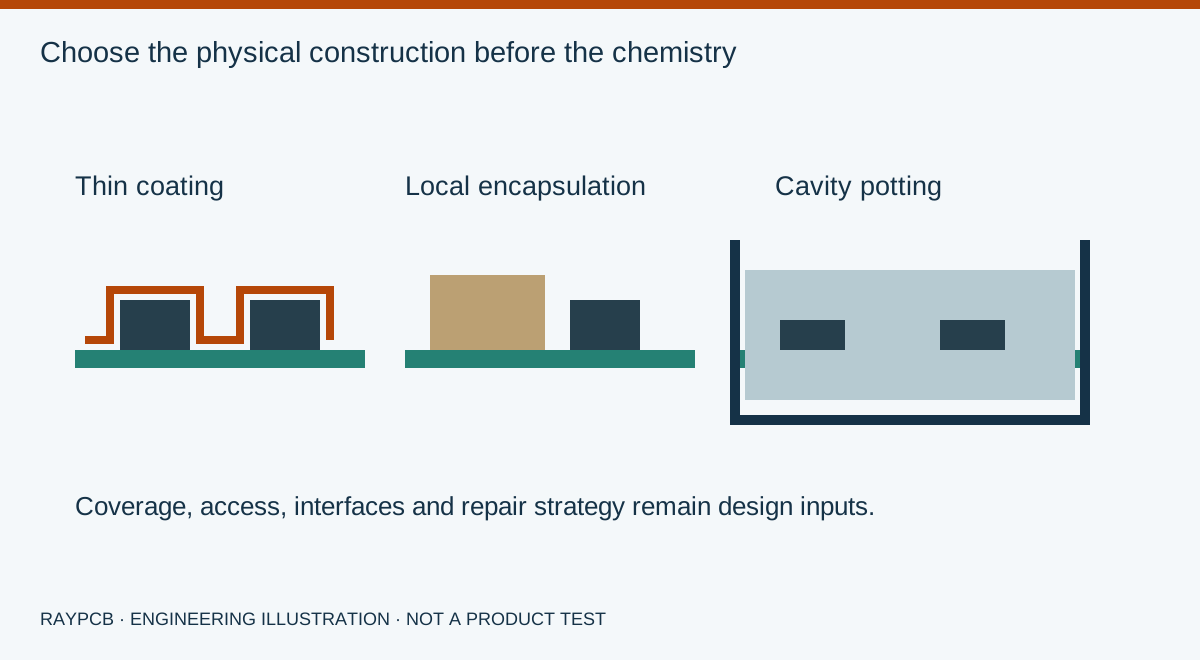
PCB encapsulation starts with the exposure, not the resin name
PCB encapsulation adds a protective material around selected electronics or an entire assembly. Depending on the construction, the material may be cast in a removable mold, retained inside the final enclosure, or applied locally around vulnerable components. Suppliers sometimes use “encapsulation” and “potting” interchangeably. Specify the physical construction and protected regions instead of relying on the label alone.
The engineering decision is a tradeoff between environmental protection, thermal behavior, mechanical stress, added mass and access for repair. A resin with an impressive property on its data sheet can still be unsuitable for a particular component, enclosure or production route. Begin with what the finished product must tolerate and what must remain accessible.
This page helps choose and document a protection approach. For fill-volume planning, mixing and cure controls, use the separate PCB potting process guide. For a commercial build request, the PCB potting services page owns the manufacturing enquiry.
Compare four physical protection strategies
| Approach | Physical construction | Useful design question | Main tradeoff to investigate |
|---|---|---|---|
| Conformal coating | A comparatively thin film follows accessible assembly surfaces | Can a serviceable enclosure and controlled coating coverage meet the exposure? | Coverage, masking, edges and repair access |
| Selective encapsulation | A defined region is surrounded or covered with protective material | Which components or connections actually need protection? | Transitions, local stress and interfaces |
| Potting in an enclosure | Resin occupies a specified cavity around the assembly | Can the fill, heat path and enclosure be qualified together? | Mass, cure behavior and loss of access |
| Molded encapsulated module | Material forms a body around the electronics, with the mold removed | How will the module mount, connect and survive service loads? | Tooling, release surfaces and dimensional control |
No row automatically establishes waterproofing or an IP rating. Complete-product performance depends on cable entries, connectors, interfaces, enclosure seals and the specified exposure as well as the protective material. A coating and a sealed housing may outperform a poorly designed full pour for a particular service condition.
Avoid buying “maximum protection” without defining what that means. A field-repairable controller and a permanently sealed sensor have different maintenance strategies. Their preferred materials may differ even when both face moisture and vibration. The goal is to protect the necessary functions while preserving the access and thermal paths the product needs.
If the decision has narrowed to these two routes, compare potting and conformal coating under the same mass, access and exposure requirements. That comparison precedes selection of an exact material and service process.
Compare your requirements before choosing a chemistry
The explorer records liquid exposure, repair expectations, heat-path readiness and sensitive functional regions. Its output is a starting discussion, not a product recommendation. It does not select a resin, certify an enclosure or calculate a lifetime. Use it to identify which evidence is missing before requesting candidate materials.
RAYPCB ENGINEERING
Assembly EngineeringPCB Protection Requirements
Loading PCB Protection Requirements…
A useful response might be “field repair required, periodic liquid contact, antenna nearby.” That combination points toward reviewing the housing, selective coverage and antenna keep-outs before assuming that a full pour is appropriate. Another project may accept permanent encapsulation but still need a measured thermal path and a qualified cure process.
You can download the brief and attach it to an enquiry. None of the worksheet inputs is automatically sent to a form or a supplier. If you already have a controlled protection drawing and material specification, contact RAYPCB directly and use those documents as the review basis.
Epoxy, polyurethane, silicone and gels are families
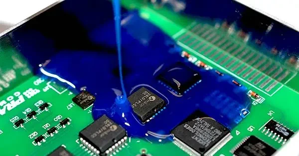
The official Electrolube encapsulation-resin directory includes epoxy, polyurethane and silicone formulations. Chemistry names narrow a search, but properties vary within each family. Ask for the exact product code, technical data sheet, safety data sheet and processing instructions.
| Candidate family | Questions worth asking | Avoid this shortcut |
|---|---|---|
| Epoxy formulations | What are the cured modulus, shrinkage, adhesion and thermal-cycle results? | “Epoxy is always the strongest, therefore it is best.” |
| Polyurethane formulations | How do moisture during processing, chemical exposure and service temperature affect this grade? | “Flexible means suitable for every outdoor product.” |
| Silicone elastomers | What are the cure system, compatibility, adhesion and permeability characteristics? | “High temperature capability makes every interface watertight.” |
| Soft gels | How will the gel be contained and protected from mechanical damage? | “Low stress means no qualification is needed.” |
Dow's silicone encapsulant and gel guide illustrates the range of viscosities and cured forms within one supplier's portfolio. Use such documents to request appropriate candidates, not to approve a substitution by matching one headline number. Keep the final selection linked to the actual construction and exposure tests.
The material order should state the exact formulation and relevant packaging. A two-part system also needs an unambiguous mixing basis. Mass ratio, volume ratio, mixed density, working time and cure schedule are separate properties. The dispensing process must use the basis specified for the selected product.
Trace heat all the way to the surroundings
A thermally conductive encapsulant can help connect a heat-producing component to a case or spreader. That does not guarantee a lower junction temperature. The thickness and area of the path, interface contact, voids, enclosure material and external cooling still matter. If heat has nowhere to leave the case, filling the cavity does not create a heat sink.
Start with a sketch of the dominant heat sources and the intended path to ambient. Identify which surfaces must make contact and which electrical insulation requirements apply. Compare the proposed assembly with its unencapsulated baseline under a controlled load and environment. Record where temperatures are measured and whether the measurements represent the limiting operating condition.
Thermal data from a material specimen is not a complete thermal model of the product. For early discussion, a slab relation such as resistance proportional to thickness divided by conductivity and area can clarify the direction of a design change. It should not replace a three-dimensional assessment or measurements where spreading, interfaces and multiple heat paths dominate.
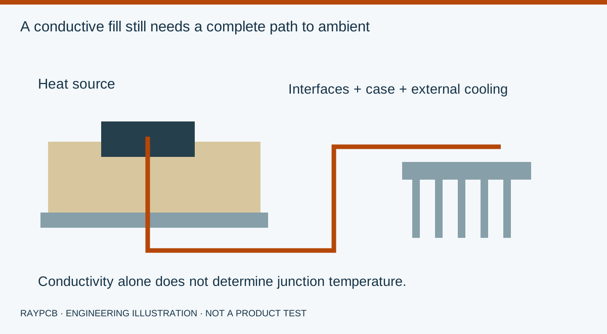
An illustrative power module may need a thin, controlled path to a metal base while leaving a connector accessible. A larger volume of the same compound above the board could add weight without improving that critical path. Reviewing the geometry can therefore reduce both material use and thermal uncertainty.
Keep protection away from functions that need access
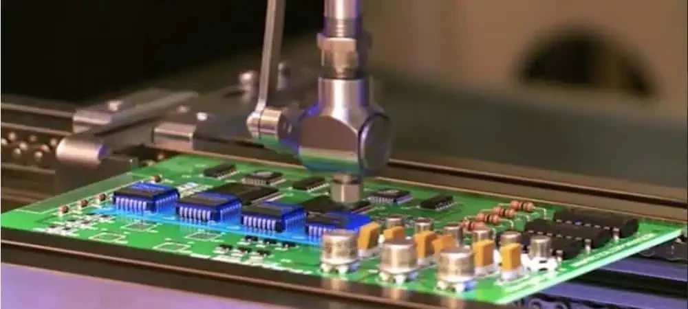
Draw explicit boundaries around connectors, switch mechanisms, adjustment features, optical windows, pressure ports, acoustic openings and required test contacts. Identify whether a boundary is a temporary mask, a permanent barrier or a designed interface in the final product. Include both sides of the assembly and the route by which liquid material could travel.
RF circuits need additional attention because nearby dielectric material can change electromagnetic behavior. Do not assume that an antenna tuned in air will retain its performance after encapsulation. Define the permitted coverage and measure the finished construction under the intended operating conditions. The same reasoning applies to sensitive optical and sensor functions: qualification must include the treated assembly.
A coating keep-out is not necessarily a potting keep-out. A deeper fill can flow beneath components, through holes or along cable strands into areas that were never exposed to a thin-film application. Review dams, vents and seals with the actual fill direction. A top-view drawing alone may miss the critical escape path.
For an existing coating specification, the conformal coating thickness guide helps separate film control from bulk protection. Do not copy a thin-film thickness callout into a cavity-fill drawing and expect the same manufacturing process.
Consider what happens when the product changes temperature
The PCB, components, encapsulant and enclosure respond differently to temperature and mechanical loading. A protective material can transfer stress into leads, solder joints, ceramic parts or interfaces. The effect depends on the actual geometry and material behavior, not only on whether the cured compound feels hard or soft.
Treat supports and enclosure attachment points as part of the encapsulation design. A board that is free to move before potting may become constrained after cure. A connector intended to absorb insertion force through the housing may instead load a small region of resin or the board. These changes should be visible in the mechanical review.
Use representative assemblies for trials, including the features most likely to be sensitive. Define observations before and after exposure: functional drift, cracks, delamination, interface leakage or other project-specific concerns. A surface that looks smooth after cure does not establish long-term compatibility with every component beneath it.
Where repair matters, demonstrate the proposed removal and rework method on a representative build. Record the damage criteria and the retest required afterward. “Reworkable resin” is incomplete unless the actual package, access and repair process have been considered.
Plan evidence around the failure mechanisms
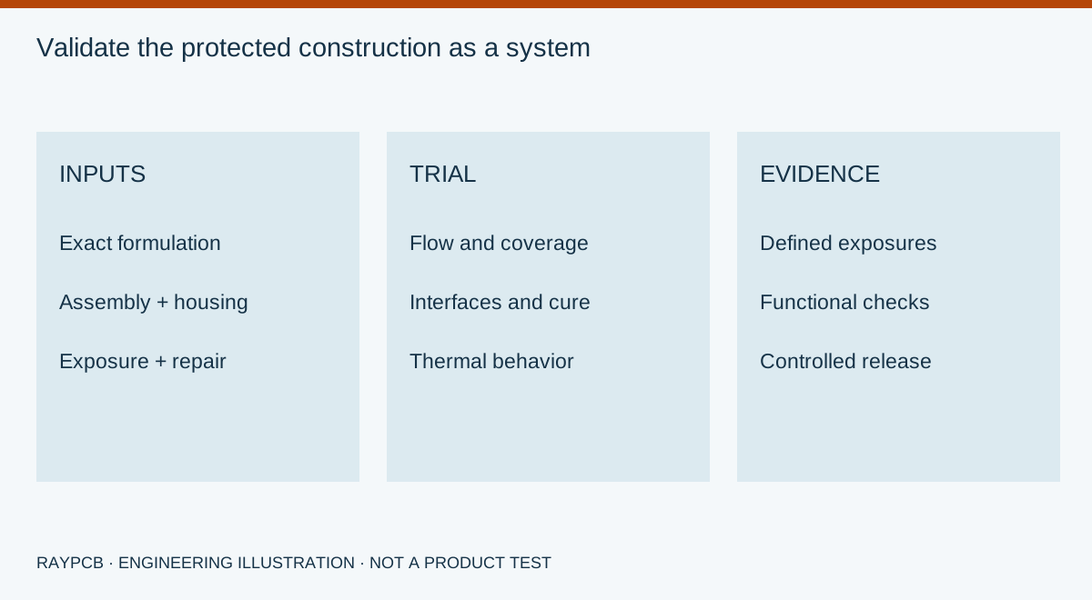
A concise qualification plan names the material, assembly revision, enclosure and intended environment. It then connects each concern to an observable result. This is more useful than ordering a long list of unrelated tests because they appear in another product's brochure.
| Concern | Evidence to define | Record to retain |
|---|---|---|
| Moisture or liquid ingress | Exposure medium, duration, pressure and acceptance response | Complete-product setup and post-exposure result |
| Thermal behavior | Load, ambient conditions and measurement locations | Temperature data and configuration |
| Mechanical compatibility | Relevant cycling, vibration or handling conditions | Before/after observations and functional checks |
| Processing consistency | Dispensing, cure and inspection controls | Material lot, process revision and build record |
| Repair or service access | Approved access and rework demonstration | Damage assessment and required retest |
The table is a planning framework, not an industry-wide test recipe. Applicable product standards and customer requirements determine the actual exposures and pass criteria. Do not claim medical, automotive or aerospace qualification from a generic resin-family comparison.
Keep evidence from exploratory trials separate from the approved production process. If the formulation, enclosure, coating underneath, component package or fill geometry changes, review whether the earlier evidence still applies. A traceable change decision is often more valuable than simply keeping the same marketing description.
What changes the cost of encapsulation?
Material cost is only part of the total. Masking, surface preparation, dispensing equipment, mixed-material waste, cure space, handling, inspection and yield can change the economics. Tooling or an enclosure redesign may dominate a small build, while cycle time and maintenance may dominate repeated production.
Ask for the cost basis to state the protected area, fill geometry, material identity, quantity and evidence requirements. Two prices cannot be compared fairly if one includes cleaning and post-process testing while the other covers resin application alone. Changes to the repair strategy may also affect future service cost even when the initial manufacturing price is lower.
The next step is a scoped request through PCB assembly, with the protection drawing and unresolved questions attached. If potting is the chosen route, use the volume worksheet on the linked potting page to prepare a material allowance. Its arithmetic does not replace a supplier quotation.
Questions about PCB encapsulation
Is encapsulation always different from potting?
Terminology varies. This page uses encapsulation as the broader protection topic and potting for a defined cavity filled around electronics. State whether the housing remains, which areas are filled and what must remain exposed.
Does resin automatically make a PCB waterproof?
No. The finished product includes interfaces, connectors, cable entries and enclosure features. Define the required exposure and verify the complete construction. A material data sheet alone does not establish a product ingress rating.
Can an encapsulated board still be repaired?
Sometimes, depending on the material, geometry, package access and approved removal process. If repair is a requirement, demonstrate it before production. Full encapsulation may be incompatible with the intended service strategy.
Should I choose the highest thermal conductivity?
Choose a material that fits the complete thermal, electrical, mechanical and processing requirements. Thermal conductivity is only one input. A well-designed interface and short heat path may matter more than a headline conductivity value.
What should I send for an initial review?
Send the assembly and enclosure drawings, protected regions, keep-outs, environment, repair expectations, quantity and any approved material candidates. Include the required verification and state which decisions are still open.
Prepare a scoped assembly review
Send the board revision, construction, quantity and the inspection, protection, programming or test question you need reviewed. Identify unresolved requirements so the response can address them.
Send requirements for reviewOptional: attach the downloaded worksheet manually. This guidance does not certify a design, approve a shipment or replace the applicable authorized standards.