
RAYPCB · ENGINEERING GUIDE
USB Port Types: Identify the Connector, Then Check Its Capability
USB port types can describe connector shapes, while product descriptions may also mention a data generation or a power capability. These are different attributes. Type-A, Type-B and Type-C names do not, on their own, tell a buyer the sustained file-transfer rate, charging power or supported display function of a particular device.
Use this guide to specify a connection for a PCB or compare a product requirement with a supplier's description. The review worksheet records the evidence for connector identity, data capability, power behavior and cable support. It does not inspect a port or certify a device. If you are already implementing a Type-C receptacle, continue to its PCB integration guide.
Start with the physical mating requirement
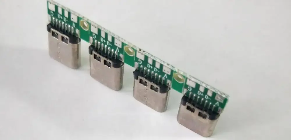
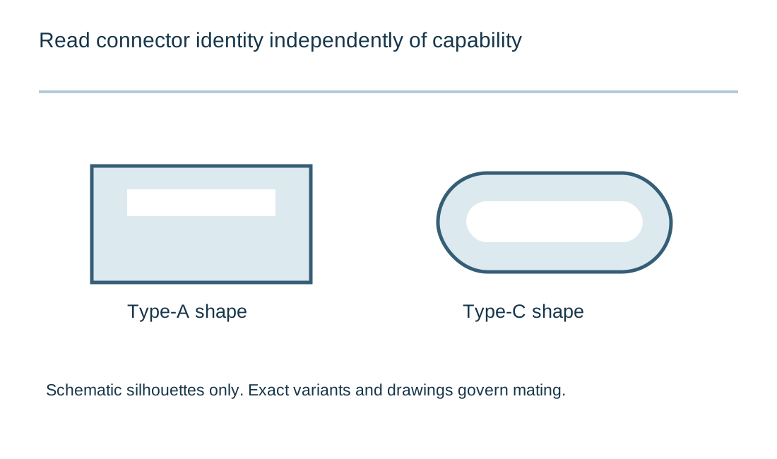
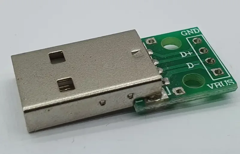
Identify the plug and receptacle that must mate, including the exact form and any relevant product variant. Type-A and Type-B families include implementations associated with different USB capabilities, and legacy Mini or Micro connectors require their own exact identification. A photograph can help identify a shape without establishing every electrical function.
For a board-mounted receptacle, obtain the actual part drawing. Mounting style, orientation, board position, contact arrangement and retention features affect the PCB and enclosure. Two connectors with a similar front opening can require different footprints or mechanical clearances.
Record the intended cable assembly as part of the connection. A cable with physically compatible ends can have a different data or power capability from another cable that looks similar. A connector selection should therefore state both the board component and the cable requirement instead of assuming either one defines the complete path.
Read a product description in four parts
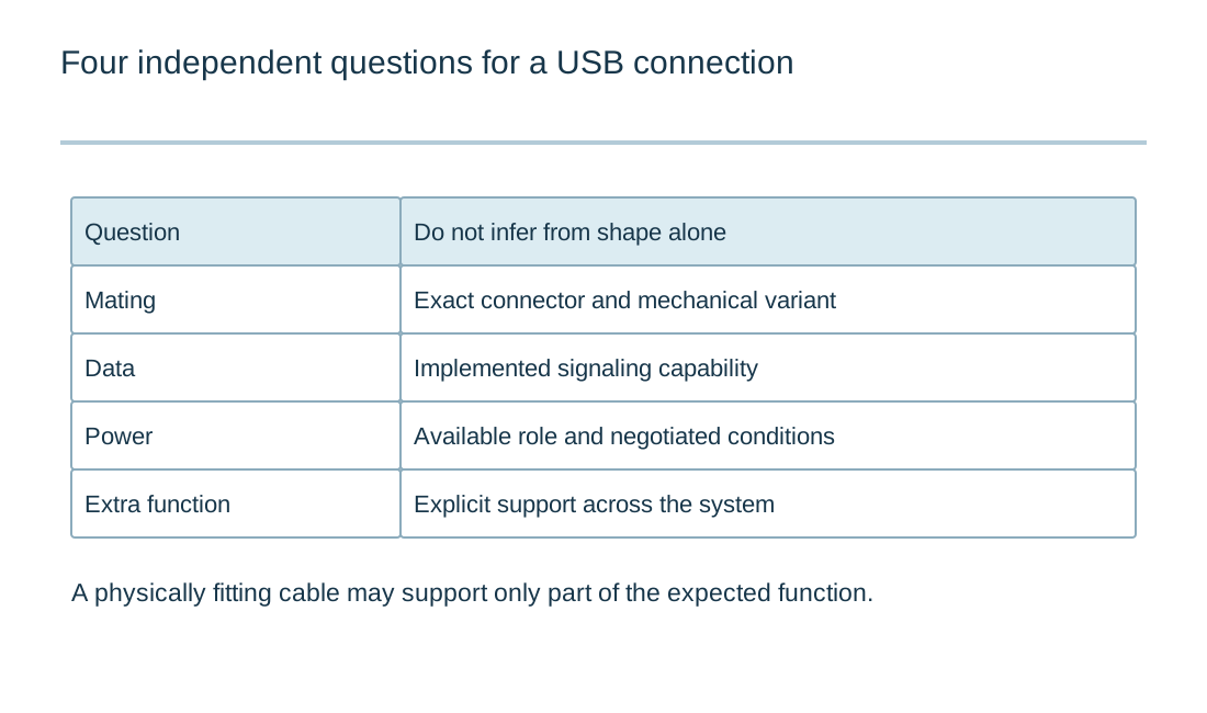
| Attribute | Example question | Evidence |
|---|---|---|
| Connector | Which plug and receptacle must mate? | Exact drawing and selected part. |
| Data | What capability is implemented across this path? | Product/controller documentation and suitable test. |
| Power | What is available under this connection and negotiation? | Port, cable and applicable operating conditions. |
| Additional function | Is the required display or other function supported? | Explicit system capability, not connector appearance. |
Keep the connector name separate from data speed
USB-IF guidance explicitly distinguishes USB Type-C connector terminology from data-performance and power claims. A Type-C product can implement a particular subset of functions. It does not become a higher-speed product simply because the connector is reversible or newer in appearance than another connector.
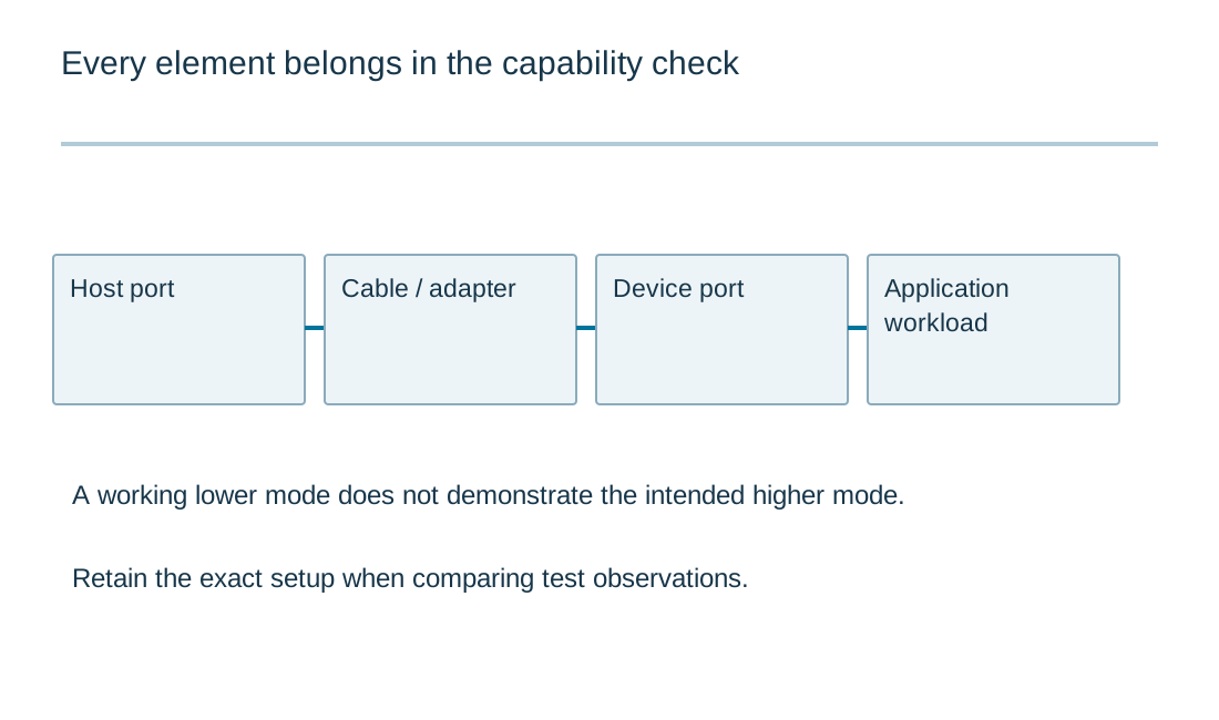
Ask for the actual supported signaling capability and the condition under which it is available. The host, device, cable and any intermediate hub or adapter all matter. A path can operate at a lower mode when one element does not support the intended capability, while still appearing functional to the user.
Keep headline signaling rate separate from application payload throughput. Protocol overhead, host scheduling, storage or processor limitations and software behavior can affect a real transfer. A purchasing requirement for measured data delivery should state the workload and test condition, not only repeat a link-rate label.
| Review item | What to establish |
|---|---|
| Physical connection | Exact plug/receptacle family, component drawing and mechanical fit. |
| Data capability | Supported signaling mode and a separate payload-performance requirement where needed. |
| Power capability | Source/sink behavior and the conditions for available power. |
| Cable and adapters | Explicit supported assemblies and intermediate equipment. |
| Evidence | Documents, functional observations and certification claims kept separate. |
USB port implementation review
USB port implementation review
Use the current inputs and keep the assumptions
Load the example to learn the worksheet, then clear it before entering your project values. Blank fields are not silently converted to zero. Units and selected conventions belong to the result, so review them together with the numbers. Editing any input invalidates the previous result and disables its download until you calculate again. Edited example data remain labeled as an illustrative example.
This tool runs locally on the values you enter. It does not open a schematic, select approved components, measure signals or inspect a physical board. Keep the exact component documents and a record of measurements with the design. Downloading the text report does not send an enquiry or populate the Contact form. Attach it manually if it helps explain a specific engineering question; completing the worksheet is optional.
| Input | What to establish before using it |
|---|---|
| Review reference | Use a nonconfidential revision reference. |
| Connector shape and exact receptacle/plug identified | Self-reported status; record evidence outside this worksheet. |
| Advertised data capability confirmed independently | Self-reported status; record evidence outside this worksheet. |
| Power role and negotiated power capability confirmed | Self-reported status; record evidence outside this worksheet. |
| Cable data/power support checked separately | Self-reported status; record evidence outside this worksheet. |
| Product labeling describes verified capability | Self-reported status; record evidence outside this worksheet. |
State the power relationship without guessing from shape
Identify whether the port supplies power, receives power or supports a documented change of role. State the power capability available under the relevant connection and negotiation conditions. A maximum capability described for the wider USB specification is not automatically available from a particular charger, computer, cable or board.
For Type-C implementations, configuration-channel behavior and any applicable Power Delivery support must be considered with the actual circuit. A source and a sink have different responsibilities. The product description should not imply that all ports with the same shape behave identically when another power source is attached.
Include the cable's role in the requirement. Current and voltage conditions, identification and supported modes depend on the applicable cable and specification. Obtain evidence for the selected assembly rather than inferring capability from thickness, color or a generic product photo.
Treat optional functions as explicit requirements
If the product needs a display output, docking feature or another alternate function, name that requirement separately. Do not assume it from a Type-C opening or a cable that successfully charges the device. The relevant controllers, paths, firmware and cable must support the intended function.
Adapters and hubs add another boundary to review. They can change the physical connection while providing only a subset of the functions expected at either end. State the allowed intermediate equipment in the test setup. A product working through one adapter does not demonstrate compatibility with every adapter sold with similar connector names.
For a PCB design, translate the requirement into a port architecture before routing. The USB PCB layout page then deals with the chosen physical channel. It cannot resolve an unspecified data role or add a function that the selected controller does not implement.
Write a specification a supplier can answer
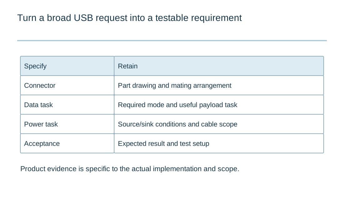
A useful port requirement names the exact mating connector or interface, supported data capability, power behavior, cable assumptions and intended use case. It also identifies how the requirement will be verified. This gives the supplier a concrete basis for answering instead of inviting a broad claim that the product supports USB-C.
Keep evidence types distinguishable. A component datasheet, a board schematic, a functional test and a certification record answer different questions. If a certification claim matters, confirm the actual product and scope through the relevant authoritative record. Do not transfer a component or cable claim to the entire finished device without evidence.
The worksheet is designed for this evidence collection. Mark an item open when the information is missing, and use the recorded-evidence option only when the supporting material exists in the project. The worksheet does not upload or evaluate those documents, so a completed checklist remains a declared review state rather than an independent approval.
Use the symptoms to narrow a compatibility problem
If a connection powers the device but transfers no data, check the cable and implemented data path before assuming the connector itself is defective. If only one orientation works, investigate the port implementation and mapped paths. If a device connects at a lower mode, identify the capability of every element in the chain and the actual operating mode reported.
When comparing test results, keep the host, device, cable and software workload consistent. Changing several items at once can hide the cause. A short compatibility record should identify the exact setup, expected behavior and observation so another person can reproduce it.
For an assembly or manufacturing enquiry, provide the board files and the actual port requirement, including any connector-position or enclosure constraints. Specify the test equipment or cable if it is part of acceptance. RAYPCB can review that build scope with the design information; a connector name alone is not enough to define the product's electrical or functional performance.
Describe the tested connection precisely
Retain the exact host, device, cable, adapters and operating mode with a result. Record the power arrangement separately from the data behavior, including connection order when it matters. A useful observation says what the product did in that setup and which requirement it was intended to check.
For a discrepancy, preserve the simplest configuration that reproduces it. Compare connector identity, port role, supported capability and physical implementation as separate questions. Changing a driver does not repair a missing electrical connection, while rerouting a pair does not add an unsupported device function. Give the next reviewer the circuit revision, expected behavior and actual evidence so the investigation can target the relevant boundary. Functional bring-up and formal compliance remain separate activities with their own documented scope.
Standards, source context and limits
The referenced manufacturer documentation supports specific devices, interfaces or design methods. Apply the version and operating conditions appropriate to the actual part. A similar product name is not evidence that pin functions, voltage tolerance, startup behavior or package dimensions match. Worked examples illustrate reasoning and arithmetic; they are not released schematics or independent hardware test results.
For fabrication scope and the agreed construction requirements, see PCB manufacturing.