Introduction
Field Programmable Gate Arrays (FPGAs) are semiconductor devices that can be configured and reconfigured to implement custom logic functions. Xilinx is a leading FPGA vendor providing a broad portfolio of FPGA families. The XC6SLX25T-2FGG484I is a specific FPGA model from the Spartan-6 series. In this article, we will take a detailed look at the architecture, features and applications of this Xilinx FPGA.
Overview of XC6SLX25T FPGA
The XC6SLX25T-2FGG484I is a mid-range FPGA from the Xilinx Spartan-6 family built on a 45nm process technology. Here are some key features:
- Logic Cells: 15,850
- Logic Lookup Tables (LUTs): 25,344
- Distributed RAM (Kbits): 448
- Digital Signal Processing (DSP) Slices: 66
- Maximum User I/O: 310
- On-Chip Memory (Kbits): 4,320
- High-Speed Transceivers: 0
- Package: FineLine BGA with 484 pins
- Operating Voltage: 0.95V to 1.2V
- Operating Temperature Range: 0°C to +85°C Industrial
These specifications place the XC6SLX25T in the mid-size FPGA segment in terms of logic capability and power consumption. It offers a good balance of resources for implementing digital circuits.
Internal Architecture

The XC6SLX25T has the following key components in its internal architecture:
Configurable Logic Blocks (CLBs)
- The basic logic building block containing LUTs and flip-flops
- CLBs implement the custom logic functions
Input/Output Blocks (IOBs)
- Located around the periphery, providing input/output connectivity
- Support common I/O standards like LVCMOS, LVDS
DSP Slices
- Dedicated blocks for arithmetic and DSP operations like multiply-accumulate
Block RAMs
- Self-contained memory blocks providing distributed storage
Clock Management Tiles (CMTs)
- Digital clock managers, phase-locked loops for clock control
Routing Matrix
- Interconnect network for routing signals between logic blocks
Configuration Memory
- Flash memory to store FPGA configuration data
This architecture allows implementing various digital logic circuits by intricately connecting and configuring the fundamental logic, memory and DSP elements.
FPGA Configuration
The Spartan-6 FPGA needs to be configured for the desired application logic after power up. This is done using configuration data stored in an external flash memory. Various configuration modes are supported:
- Master Serial – Serial data from flash loads config
- Master Parallel – 8-bit parallel transfer from flash
- SelectMAP – 8 or 32-bit parallel transfer, fastest method
- Peripheral – SPI, USB, Ethernet can load config
The ICAP (Internal Configuration Access Port) allows reconfiguring the FPGA any time after initial load. This dynamic reconfiguration capability enables updating the design in-field.
Development Tools and Software
Xilinx offers a comprehensive suite of development tools and software to program the XC6SLX25T FPGA:
- Vivado Design Suite – For synthesis, place and route, simulation
- SDK (Software Development Kit) – Software libraries, drivers, OS support
- IP (Intellectual Property) cores – Logic cores for common functions
- EMBD (Embedded Development Kit) – Embedded processor tools
- ChipScope – Debug and verification utilities
Designers can leverage these tools to code in Verilog/VHDL, synthesize, implement and debug custom FPGA designs. Higher level languages like C/C++ can also be used with available compilers.
Target Applications
The Spartan-6 family containing the XC6SLX25T targets cost-sensitive, high-volume applications including:
- Automotive driver assistance systems
- Industrial automation and control
- Communications infrastructure
- Consumer electronics
- Smart vision systems
- Medical equipment
- Defense electronics
Mid-size FPGAs like the XC6SLX25T offer sufficient resources for such applications while minimizing cost and power demands.
Some specific applications include:
- Motor drives
- Software-defined radio
- Surveillance systems
- IoT endpoints
- Broadcast cameras
- DNA sequencing
- Wireless basestations
Benefits of XC6SLX25T FPGA
Some benefits offered by the Xilinx XC6SLX25T for developers include:
- Optimized price/performance for mid-range applications
- High logic density in small form factor
- Low static and dynamic power consumption
- High DSP capabilities with dedicated blocks
- Scalable density for diversified applications
- Support for high-speed differential I/O
- Fast time-to-market using IP cores
- Proven and mature technology with long availability
In summary, the XC6SLX25T provides a versatile mid-size FPGA platform for building a wide variety of digital systems.
Comparison with Other FPGAs
The XC6SLX25T sits between the smaller Artix-7 and larger Virtex-6 FPGA families from Xilinx.
Compared to the Artix-7 series, it offers higher density but lower performance. The Virtex-6 is more advanced but has much higher cost and power profile.
Among competitor FPGAs, the XC6SLX25T is comparable to mid-range offerings from Intel (formerly Altera) like the Cyclone V series or Microsemi IGLOO2 FPGAs.
Conclusion
The Xilinx XC6SLX25T-2FGG484I provides a mid-capacity FPGA in the Spartan-6 series with around 15K logic cells and 25K LUTs. It strikes an optimal balance of logic resources, performance, power consumption and cost. The FPGA is suited for a wide breadth of applications in automotive, industrial, communications, consumer and other segments. With available IP cores and software, the XC6SLX25T enables fast creation of functional prototypes and production designs. In summary, it gives embedded systems designers an efficient and capable programmable logic platform for realizing their digital visions.
Frequently Asked Questions
What are the key differences between the XC6SLX25T and newer 7 series FPGAs?
Compared to the Artix-7 and Kintex-7 families, the XC6SLX25T is based on older 45nm technology offering lower performance but better cost efficiency. The 7 series uses more advanced 28nm manufacturing.
What is the maximum clock speed supported by the XC6SLX25T device?
The XC6SLX25T FPGA can support up to 450 MHz clock frequencies depending on the design complexity. Simple logic can run faster than heavily loaded complex designs.
Does the XC6SLX25T have any hard processor cores?
No, the XC6SLX25T does not contain any internal microprocessor cores like MicroBlaze or ARM. Soft processor cores would need to be implemented in the FPGA fabric if required.
What is the typical power consumption of the XC6SLX25T FPGA?
Static power is around 90mW. Dynamic power ranges from 200mW for modest designs up to 1W for heavily loaded complex logic running at high speeds.
What embedded peripherals are available in the XC6SLX25T?
Commonly used peripherals like GPIO, UART, timers, PWM generators, bus interfaces like SPI can be instantiated using the IP library blocks provided by Xilinx.
Xilinx XC6SLX25T-2FGG484I FPGA Project Board
Xilinx is one of the top manufacturers of Field Programmable Gate Arrays (FPGAs), which are used to reprogram and add additional features to manufactured semiconductor devices.
This article is about the Xilinx XC6SLX25T-2FGG484I. It is one of the project development boards classified under the Xilinx Spartan-6 project boards.
You will find out more about the technical specifications of the board, as well as the use cases.
Technical Specifications
Here are some of the technical specifications of the Xilinx -2FGG484I:
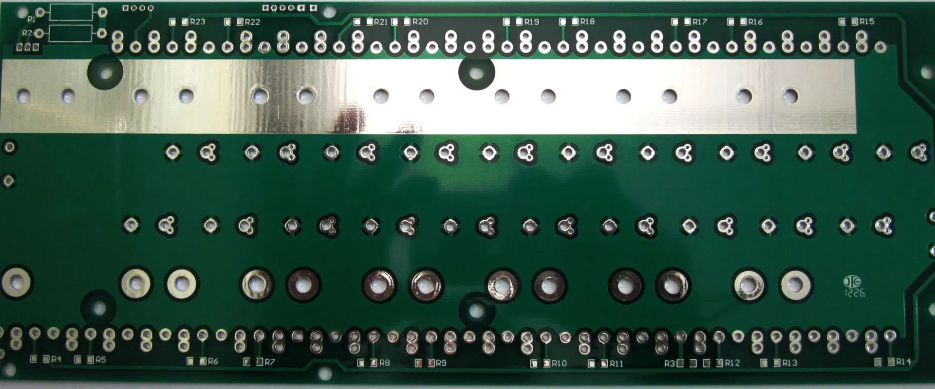
1. Mounting Type
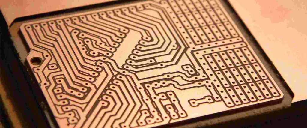
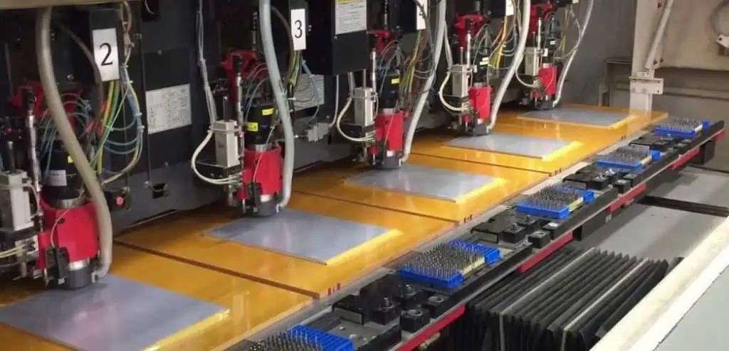
This project board is designed to use Surface Mount Technology (SMT). It is interesting to note that SMT is one of the latest processes of manufacturing circuit boards.
This is because the process only requires the placement of the components on top of the board. So, if you are investing in the Xilinx XC6SLX25T-2FGG484I, you can be confident that the components would be integrated in real-time.
2. Programmable Logic Type
Again, the Xilinx XC6SLX25T-2FGG484I uses Field Programmable Gate Array (FPGA) as the programmable logic type.
This is one of the best features because it allows designers to have a stress-free time in making changes to semiconductor devices.
3. Lead Time
The lead time of the Xilinx XC6SLX25T-2FGG484I has to do with the amount of time required to start the production of the project board and to finish the same.
It also has to do with the chain of steps to take during the manufacturing stages, including the supply chain management, and project management, especially during the pre-processing, processing, and post-processing stages.
For the Xilinx XC6SLX25T-2FGG484I, manufacturers require a lead time of 52 weeks. This may vary by the manufacturer you are ordering the board from, but 52 weeks is the standard lead time.
4. The CLBs
The CLBs stand for Configurable Logic Blocks. Without the presence of these blocks on FPGAs, it would be hard to add additional logic functions or reprogram the device.
To that end, you want to invest in the Xilinx XC6SLX25T-2FGG484I, because it has up to 1,879 Configurable Logic Blocks (CLBs). Besides, these CLBs/LABs offer the designers multiple options to reprogram and include additional logic functions to the device where the board is being installed.
5. Speed
Speed is of the essence, as far as reprogramming of logic functions is concerned. In the case of the Xilinx XC6SLX25T-2FGG484I, the speed of the board is bolstered by the 958,464 RAM Bits that improve the speed of the board, as well as the accuracy of the reprogrammed logic functions.
6. Logic Elements/Cells
The logic elements/cells on Xilinx XC6SLX25T-2FGG484I combine with the Configurable Logic Blocks (CLBs)/LABs to improve the functionalities of the reprogrammable features of the bord.
These logic elements or cells are considered add-ons because they help the designers to include additional logic elements and properties that will improve the aesthetics of the designs they are working on.
The Xilinx XC6SLX25T-2FGG484I offers up to 24,051 logic elements/cells, which is quite impressive. With this large volume of logic elements, designers can now reprogram the logic functions of semiconductor devices with ease.
7. Voltage Supply
Voltage is of the utmost importance in the reprogramming of the logic functions of semiconductor devices on different devices.
The voltage supply of the Xilinx XC6SLX25T-2FGG484I is a minimum of 1.14 volts and a maximum of 1.26 volts.
The voltage of the Xilinx XC6SLX25T-2FGG484I can also be nominal at 1.12 volts.
Use Cases/Applications
Generally, the Xilinx XC6SLX25T-2FGG484I is used for reprogramming semiconductor devices on different electronic devices, including Personal Computers (PCs).
That notwithstanding, the board can be used for many other purposes. Here are some of them:
1. Used for a Variety of Digital Applications
One of the applications/uses of the Xilinx XC6SLX25T-2FGG484I is that it can be used for a variety of digital applications.
This use case is accentuated by the inclusion of external connectors, external non-volatile memory, and several I/O devices that make widespread applications possible.
2. Classroom Applications
Another use case/application of the Xilinx XC6SLX25T-2FGG484I is that it can be used in the classroom setting – either at high school or the university.
Ideally, the Xilinx XC6SLX25T-2FGG484I is designed with the latest Xilinx technologies, which make it easier for students and teachers to gain additional experience with FPGAs.
Besides, students who are new to logic circuit design and device reprogramming can utilize the Xilinx XC6SLX25T-2FGG484I to build a wide range of logic circuits.
The development of those logic circuits would also be free of the complex external interfaces.
Spartan-6 Family Overview
Xilinx XC6SLX25T-2FGG484I is one of the Field Programmable Gate Arrays (FPGAs) under the Spartan-6 family. As such, it includes most of the features that are exclusive to other FPGAs under the Spartan-6 family.
Here are some of the features of the Spartan-6 FPGAs, which the Xilinx XC6SLX25T-2FGG484I also inherits:
1. Abundant Logic Resources
The XC6SLX25T-2FGG484I, like most of the Spartan-6 FPGAs, has an abundance of logic resources. These resources are in place to help designers in facilitating the reprogramming and reconfiguration of logic devices.
The logic resources in this case include:
- Dual flip-flop LUTs designed for pipeline-centric applications.
- A distributed RAM support.
- Features 6-input Look-Up Tables (LUTs) that minimize power and improve the efficiency of the logic functions of the board.
2. Improved Security
The improvement of the security features of the Xilinx XC6SLX25T-2FGG484I is designed to enhance the protection of the designs that would be made out of it.
To that end, the following enhanced security features are included in it:
- AES Bitstream encryption is designed for use in larger devices.
- Design authentication via unique Device DNA Identifier.
3. Low-Cost Designs
The Xilinx XC6SLX25T-2FGG484I is also cut out for low costs. The costs are reduced in various ways, such as:
- High-volume plastic wire-bonded packages.
- Multiple efficient integrated blocks
- Staggered pads
- High I/O Standards with optimized selections.
4. Efficient Clock Management
The Xilinx XC6SLX25T-2FGG484I, like the other Field Programmable Gate Arrays (FPGAs) manufactured by Xilinx, has efficient clock management.
This feature is bolstered by the Clock Management Tile (CMT) that improves the performance of the board.
The features of the Clock Management Tile (CMT) are:
- Phased-Locked Loops (PLLs) that enhance low-jitter clocking.
- Flexible clocking
- Low noise clocking
- Duty cycle distortion and clock skew elimination via the Digital Clock Managers (DCMs).
Final Words
The XC6SLX25T-2FGG484I is an exciting Field Programmable Gate Arrays (FPGAs) project board to work with because it offers improved logic programming capabilities. You want to contact a reliable manufacturer or distributor of the Xilinx XC6SLX25T-2FGG484I to supply you with a functional board for your wide range of projects and designs.