
RAYPCB · ENGINEERING GUIDE
PCB Aspect Ratio: Depth, Diameter and the Correct Hole Basis
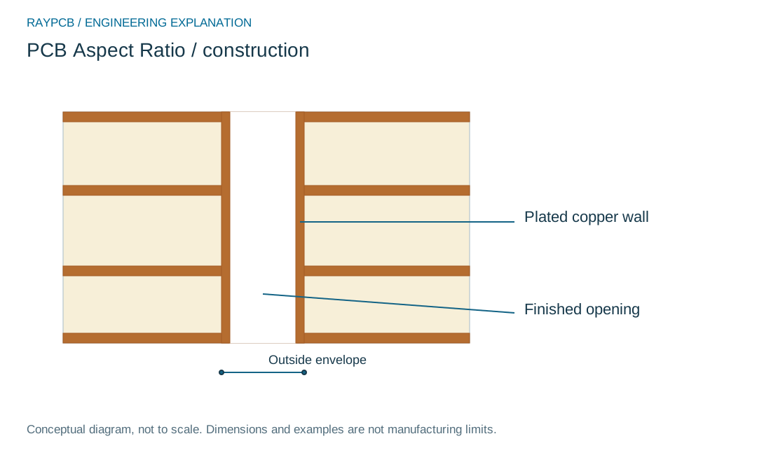
PCB aspect ratio is a depth-to-diameter relationship used to describe a hole's geometry. For a through hole, the relevant depth is commonly the board or drilled structure thickness. For a blind or buried connection, it can be a much smaller local depth. Always state which diameter and depth are being used before comparing capability figures.

One ratio can hide several definitions
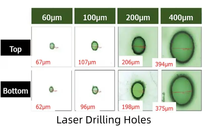
A mechanical drill diameter is not the same as a finished plated bore. A tapered microvia has different top and bottom openings. A buried hole is formed in a subassembly whose thickness may differ from the finished board. Without these definitions, two quoted aspect ratios can describe different physical features.
The worksheet accepts the actual depth and diameter selected for the review and labels the basis. It calculates depth divided by diameter. It does not decide which convention a supplier uses or replace a project-specific capability discussion.
Declared-basis aspect ratio
Declared-basis aspect ratio
Use the current inputs and keep the assumptions
Start with the example to understand the units and output, then use Clear for my inputs before entering your project. Example mode stays visibly labeled even if you edit its numbers. The form begins without a result so an illustrative value cannot be mistaken for an approved requirement. Every field must have a valid value; zero is accepted only where it has a meaningful role in the particular model.
Read the input notes before calculating. They identify the physical boundary and what is excluded. Keep the same unit convention across the drawing and worksheet. Changing an input invalidates the previous result and disables its download until you calculate again. This prevents an old number from appearing to describe a revised geometry.
The result is a screening record. A negative margin or an out-of-range condition identifies a question to resolve; a positive margin is not a manufacturing approval. Use the record with the actual drawing, material and project requirement. The model does not load CAD files, inspect images or retrieve private factory data.
Download the current result if it helps the discussion. The text includes the entered inputs, result and limitations. It stays on your device until you choose to attach or share it. Contact is a separate step; this page does not automatically populate the enquiry form or upload a file. Avoid confidential identifiers if you only need an exploratory calculation.
| Input | What to establish before using it |
|---|---|
| Review reference | Use a nonconfidential reference that lets you connect this calculation to the correct drawing revision. |
| Relevant drilled or cavity depth · mm | Use the actual structure depth at the operation. Buried subassemblies and blind connections can be shallower than the finished board. |
| Declared diameter basis · mm | Use the agreed drill, finished-bore or microvia opening basis. Do not compare the result with a capability using another convention. |
| Diameter convention | The basis is included in the output so a numeric ratio remains interpretable. |
Example: the diameter basis changes the number
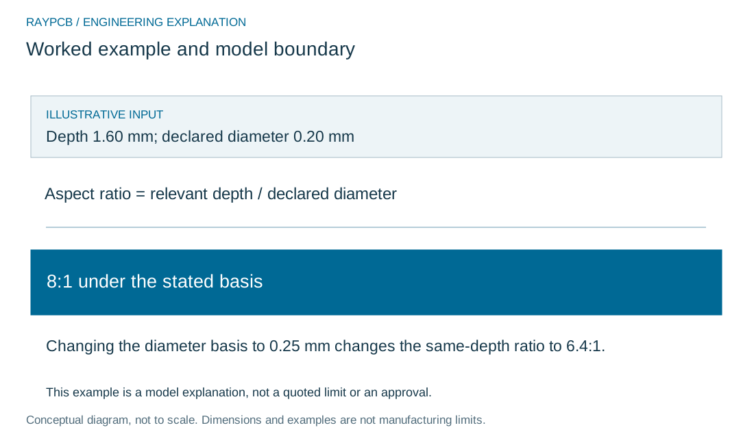
An illustrative 1.60 mm depth divided by a 0.20 mm diameter gives 8:1. Using a 0.25 mm drill basis for the same depth gives 6.4:1. Neither number is meaningful as a capability comparison unless the supplier's definition matches. The arithmetic is simple; the manufacturing interpretation is the important part.
For a 0.10 mm local blind depth and a 0.10 mm entrance diameter, the ratio is 1:1 under that convention. A smaller bottom diameter yields a different ratio. State both dimensions when the shape matters rather than hiding taper inside one number.
Why geometry affects manufacture
Deep narrow openings can be more demanding to prepare, wet, metallize, plate and inspect. Mechanical drilling also depends on tools, material and stack conditions. The ratio summarizes geometry but does not capture hole count, diameter distribution, resin system, glass reinforcement or required copper quality.
A simple ratio therefore cannot rank all boards by difficulty. Two holes with the same ratio but very different absolute dimensions may require different processes. Material and the intended fill route can change feasibility even when depth and diameter are unchanged.
Use the local structure for internal connections
For a buried via, identify the subassembly depth at the relevant operation. For a laser-drilled blind hole, identify the target layer and dielectric thickness. Do not use total board thickness merely because it is the easiest value to find in the drawing.
If the stackup changes after quotation, repeat the review. A layer-count label such as ten layers does not establish drilled depth, because dielectric and copper thickness choices can differ substantially.
Avoid universal limits
Published manufacturer limits are tied to their processes and stated conditions. They are not universal physical boundaries or transferable RAYPCB guarantees. Ask for the applicable range and evidence for the proposed material, hole type and acceptance scope. Where a design is near a quoted limit, resolve the actual tolerance envelope rather than relying only on nominal values.
The tool can compare two entered geometries by rerunning the calculation, but it intentionally does not show a green 'manufacturable' badge. A ratio is one input to a manufacturing decision, not the decision itself.
Release and quote inputs
State the depth, diameter basis, finished-hole requirement, material, layer span and copper requirement. Include any fill or cap treatment. Identify the most demanding hole family so the fabricator can review it without searching through an entire design for the controlling feature.
Does a lower ratio always mean a cheaper board? No, other operations may dominate. Does plating thickness belong in the diameter? It depends on the declared convention; do not mix bases. Can the calculator choose a production drill? No. Use the result to make a precise question that the manufacturer can answer against a defined construction.
Turn the hole budget into a measurable requirement
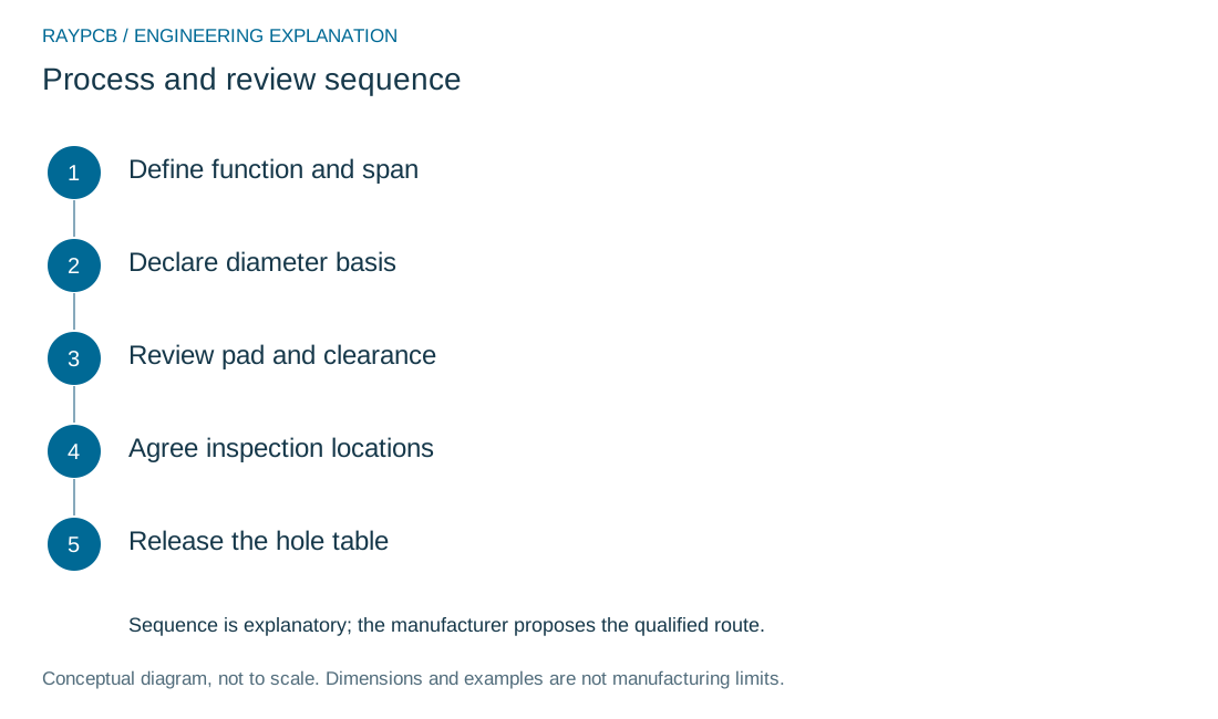
Choose one controlling hole family and follow it through the complete drawing. Begin with its function and layer span, then identify the opening before plating, the finished bore and the surrounding copper. Add the tolerance basis to each dimension. This prevents a nominally generous design from becoming marginal after several individually permitted variations are combined.
A useful manufacturing question includes both a requirement and a location. For example, ask whether the proposed finished-hole tolerance can be maintained for the identified connector pattern in the specified board thickness. That is more precise than asking for the smallest hole available. Separate a dimensional requirement from a request for a particular production tool; the latter may unnecessarily constrain the shop's compensation strategy.
When several uncertainty sources are involved, agree how they are combined. A conservative sum of absolute bounds is different from a statistical analysis. The worksheets on this page use simple declared bounds and do not estimate process capability indices. If a tolerance is quoted as a diameter, a radius or a positional zone, preserve that distinction during unit conversion. A factor-of-two error can consume the apparent margin of a small feature.
Next, decide what evidence answers the requirement. A pin gauge, optical dimension, microsection and electrical continuity test observe different things. The inspection method must be capable of assessing the named characteristic with suitable resolution and uncertainty. Record sample location and whether the value represents a minimum, a nominal dimension or an average. A mean value cannot silently replace a local-minimum requirement.
For prototypes, identify which assumptions the build is intended to check. For repeated orders, retain the approved hole table and construction revision so later material or process changes trigger the right review. If the supplier proposes a larger drill, different land or altered tolerance, assess the functional consequence before changing the release. Keep any approved deviation linked to the specific revision and quantity rather than turning it into an undocumented permanent rule.
There is no need to complete every worksheet before asking a question. A marked drawing of the difficult hole, the stackup and the intended function can be enough to start a focused discussion. The purpose of the geometry is to expose the decision, not to create another barrier between an engineer and a manufacturing response.
Standards, source context and limits
Use the performance and acceptance documents named in the procurement agreement, including their revisions and any applicable addenda. A design guide explains choices; a product acceptance requirement defines what must be demonstrated. Neither a reference link nor a calculator result is a certification of the board or the supplier. Where a value is contractually important, check the controlled document and agree the measurement method with the responsible parties.
Examples on this page are deliberately labeled and are not advertised RAYPCB limits. Supplier documentation is linked for the specific material or process context it explains. Equipment photographs and cross-section examples show the subject; they are not current production, inspection or qualification records for your order.