RAYPCB · ENGINEERING GUIDE
SMT Solder Short Inspection: Locate the Connection Before Rework
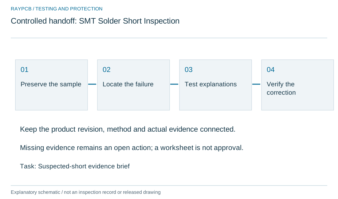
SMT solder short inspection should first establish whether an unintended electrical connection exists and where it is located. A bright line in an image, a continuity beep or a warm component is evidence to interpret, not a complete diagnosis. Parallel paths and low-impedance power networks can complicate electrical readings.
This page presents an evidence sequence for qualified electronics work. It does not recommend uncontrolled current injection or repeated power cycling. Preserve the board and its history before removing the feature that may explain the failure.
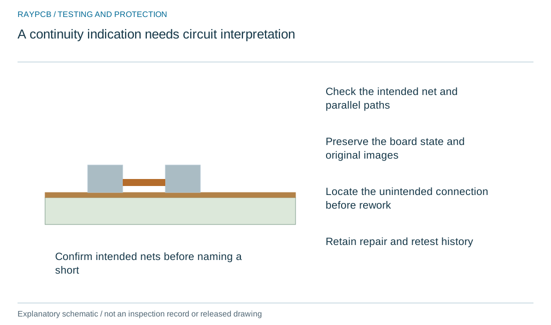
Confirm the intended network
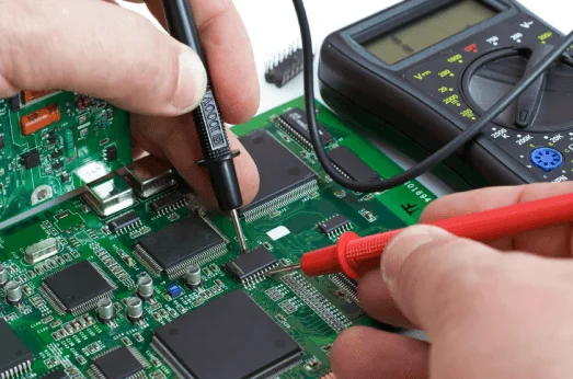
Compare the measured nodes with the correct schematic and netlist. Some pads are intentionally connected through copper, inductors, low-value resistors or semiconductor paths. A continuity indication alone does not distinguish these from an unintended bridge.
Record the meter mode, polarity, board state and measurement locations. Begin with a safely de-energized and appropriately discharged assembly using the applicable work procedure. The component-testing guide explains why in-circuit readings can differ from isolated component values.
Inspect visible interfaces with suitable optics
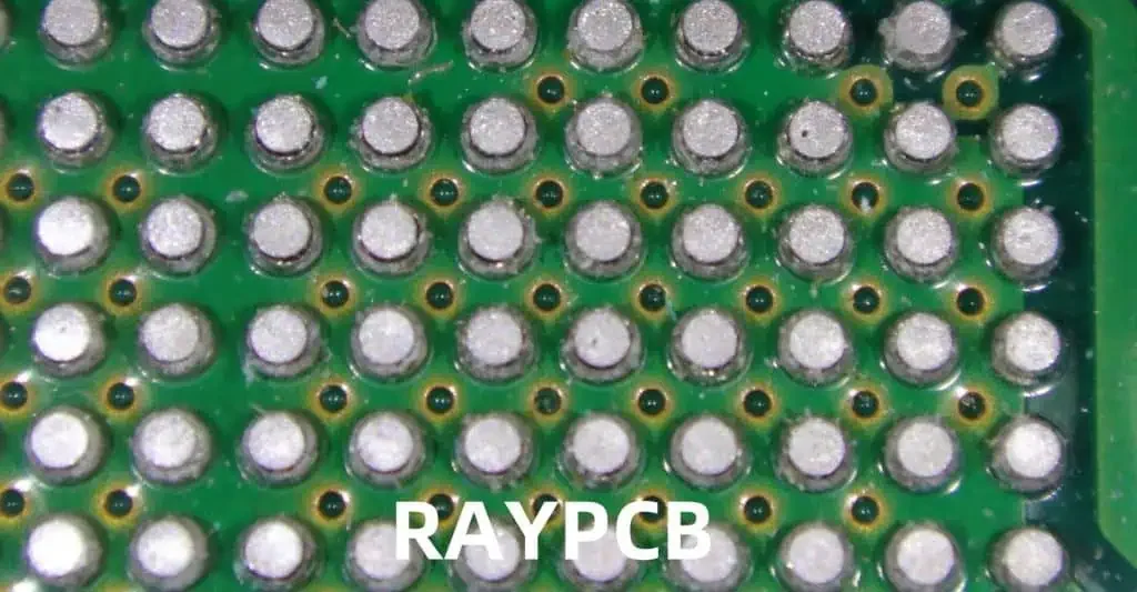
Examine accessible leads, pads and neighboring features under appropriate illumination and magnification. Identify the actual material crossing the separation, its attachment and the affected references. Keep images before touching or cleaning the area.
For hidden joints, select an appropriate method such as the planned BGA inspection route. An optical image of the package edge does not establish the state of interior balls.
| Review item | What to establish |
|---|---|
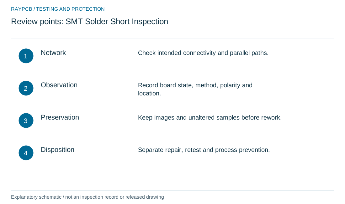
| Network | Check intended connectivity and parallel paths. |
| Observation | Record board state, method, polarity and location. |
| Preservation | Keep images and unaltered samples before rework. |
| Disposition | Separate repair, retest and process prevention. |
Use electrical localization without assuming a cause
Compare the suspect path with the design and, where appropriate, a controlled reference assembly. Changes with probe polarity, time or operating state may indicate component behavior rather than a simple metallic bridge.
Specialist localization methods require suitable equipment and reviewed limits. Do not apply improvised high current to make a short reveal itself. The goal is to locate the fault without destroying evidence or damaging otherwise good circuits.
Relate the finding to the process stage
A bridge observed after reflow may relate to paste, placement, geometry, soldering or contamination, but the appearance alone does not select the mechanism. Review the earliest available print and placement evidence for the same location.
The SPI prevention guide addresses deposits before assembly. A recurring location-specific pattern deserves a different investigation from a random particle or a broad process shift.
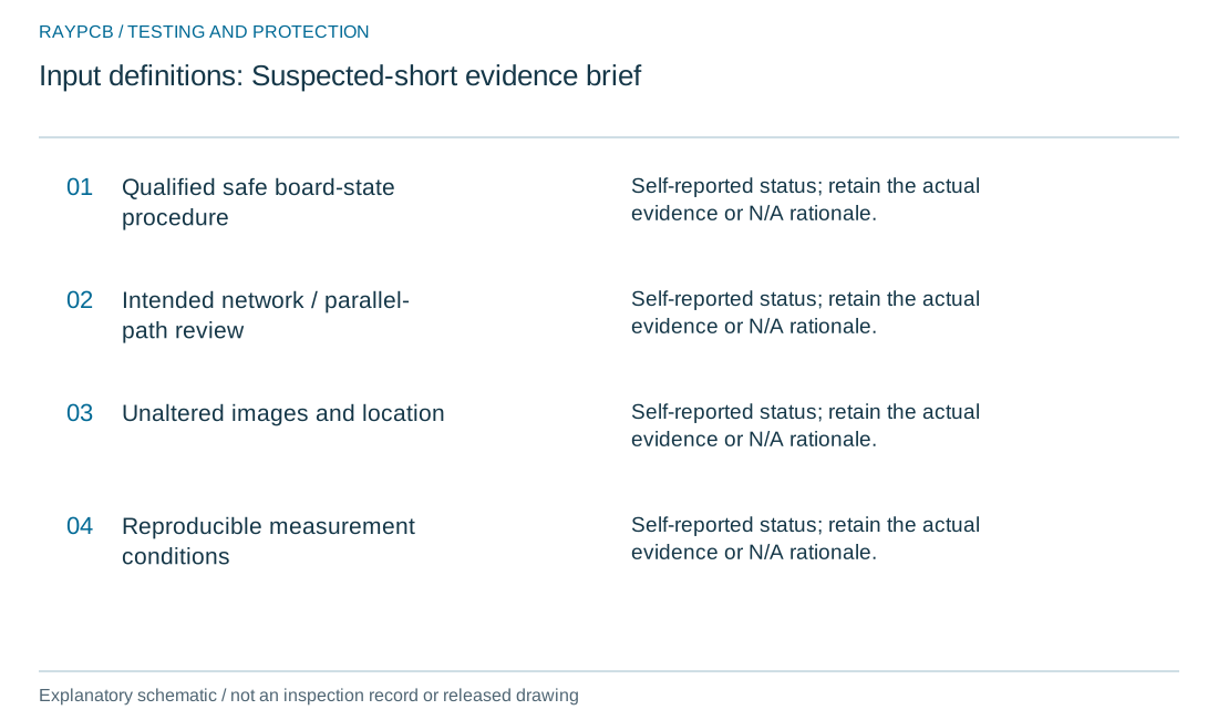
Suspected-short evidence brief
Suspected-short evidence brief
Use the current inputs and keep the assumptions
Choose the engineering question before entering numbers. Fields begin blank. Load example fills teaching values so you can understand the model; those values are not recommended dimensions, process settings or market prices. The example label remains visible after edits. Reset before preparing a record based entirely on your own project data.
Use the displayed units and keep a reference for each input. Counts must describe the same scope, and measurements must share the declared conditions. A threshold entered by you remains your supplied review condition. The website does not turn it into an IPC limit or an approved product requirement. If the necessary value is unknown, obtain the evidence rather than replacing it with an attractive assumption.
Read the result and its limitations together. An access fraction is not fault coverage, a cost allowance is not a quotation, and a completed evidence checklist is not a safety or quality approval. Negative margins remain visible where the model permits them. They identify a conflict in the entered scenario rather than silently adjusting the result.
Changing an input invalidates the result and disables its download until you run the tool again. The text record contains the inputs, result and limitations. Processing stays in your browser; no CAD files, instruments or certificates are read. No data is automatically transferred to the enquiry form. Download and attach the record manually if useful, or contact RAYPCB directly without completing the tool.
| Input | What to establish before using it |
|---|---|
| Review reference | Use a nonconfidential revision or scope reference. |
| Qualified safe board-state procedure | Self-reported status; retain the actual evidence or N/A rationale. |
| Intended network / parallel-path review | Self-reported status; retain the actual evidence or N/A rationale. |
| Unaltered images and location | Self-reported status; retain the actual evidence or N/A rationale. |
| Reproducible measurement conditions | Self-reported status; retain the actual evidence or N/A rationale. |
| Approved disposition and retest scope | Self-reported status; retain the actual evidence or N/A rationale. |
| Next action / record reference | Use a nonconfidential reference; this tool does not verify the record. |
Agree repair and retest separately
Once the condition is confirmed, use an approved repair or rework disposition. Record what was removed or changed, inspect the affected area and repeat the tests needed to verify the corrected assembly. A continuity change alone may not establish that adjacent features remain sound.
Keep the original failure in the traceability record. Counting the repaired unit as an original first-pass success distorts process information and can hide the need for prevention.
Example: a beep on a power rail
An illustrative board produces a low-resistance indication between a supply rail and return. Before naming a solder short, review the expected circuit, capacitor charging behavior and connected devices. Compare under consistent measurement conditions and follow the qualified diagnostic plan.
If a visible bridge is subsequently found, correlate its location with the electrical path. The diagnostic conclusion should rest on the combined evidence, not on the initial beep alone.
Prepare a useful failure review request
Provide the board revision, affected nodes, observed symptom, safe measurement records, images and any prior repair or powered tests. State whether the issue is isolated or recurring and preserve representative unaltered samples.
For unresolved mechanisms, continue to PCB failure analysis. RAYPCB can review the manufacturing question and requested inspection scope without treating the online evidence brief as a remote diagnosis or release approval.
Questions to resolve before the next build
Does a low resistance always mean a solder bridge? No. The circuit may intentionally contain a low-resistance path, and the instrument response can depend on connected devices and stored charge. Review the schematic and the measurement conditions before assigning the cause. Use suitable safe procedures and preserve the board state so that the observation can be reproduced and interpreted.
Can removing the bridge close the investigation? It may correct the immediate connection, but a recurring production issue still needs prevention. Record the location, process history and repair, then verify the affected assembly and examine the likely mechanism. If the original evidence has already been altered, state that limitation rather than presenting a speculative root cause as confirmed.
Preserve evidence while narrowing the cause
Make the investigation reproducible before making it broader. Record the exact symptom, product revision, conditions and observations already made. Identify which statements are measured, which are reported by the customer and which are hypotheses. This prevents an early guess from becoming the accepted explanation without supporting evidence.
Preserve the specimen's value. Cleaning, probing, powering, flexing, reheating and component removal can change the condition being investigated. Plan those actions under qualified procedures and document interventions. Where possible, retain an unaltered sample and a suitable comparison unit so that later methods still have meaningful evidence to examine.
Use the schematic and construction to interpret readings. Parallel paths, active devices, stored charge and the measurement interface can affect an observation. A familiar meter indication is not enough to identify a failed component. State the electrical path, instrument mode, reference and board state so another reviewer can understand the result.
Choose the next method to distinguish explanations. If two plausible mechanisms predict the same observation, repeating that observation may add little. Ask what evidence would separate them and whether obtaining it would destroy information needed for another method. This keeps the investigation purposeful rather than turning it into a checklist of every available laboratory technique.
Contain the operational problem while preserving technical uncertainty. Production may need a hold, additional screening or replacement material before the root cause is fully established. Record the basis and limits of that containment separately. A temporary action that restores operation does not automatically prove the cause or prevent recurrence.
Verify the remedy against the supported mechanism. A repaired board that passes one check may still require additional inspection or testing after the intervention. Update the relevant design, supplier requirement or process control when the cause is confirmed. Keep the original failure and repair history visible instead of replacing it with a final pass flag.
Prepare the enquiry around the decision needed. State whether the goal is identifying a defect, choosing a repair, evaluating a lot or preventing recurrence. Include the evidence already available and the sample constraints. RAYPCB can then review the manufacturing-related scope while specialist analysis, product safety decisions or unresolved design requirements remain clearly assigned.
Standards, source context and limits
Use each reference for its stated scope. Equipment and material documentation applies to the identified product and conditions. A published study describes its own specimens and methods; its settings are not universal production limits. Public standard summaries and revision tables do not replace the controlled normative document.
Agree the applicable standards, revisions, product class where relevant, measurement methods and exceptions before production. Distinguish printed-board requirements, assembly workmanship, laboratory competence and finished-product certification. A method name or photograph does not establish that a supplier holds an accreditation or that a particular test is included in an order.
Archive photographs illustrate relevant boards, equipment or operations from the existing RAYPCB website. They are not evidence of current equipment ownership or results from your project. Original diagrams explain concepts and measurement boundaries; they are not inspection records or released manufacturing drawings. Confirm the actual service and reporting scope in the project review.