With the dynamic changes in the field of technology, designing electronic models requires a reliable and up-to-date components system. It is therefore essential to choose wisely which components are suitable for your model. SMD diodes, therefore, fit the level of technology we have in the current world. Deciding on a suitable SMD diode requires a proper understanding of SMD diode dealers. Below are the top 10 SMD diode manufacturers in the world.
Infineon Technologies Company Ltd.
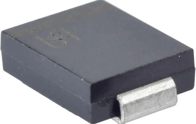
Diode
Founded in 1999, Infineon is a German company that mainly specializes in manufacturing SMD diodes. The company has particular expertise in semiconductors, as well as automotive systems. These components are used in automotive, electronic appliances, assembling companies, etc. Infineon company has other branches in Milpitas, California, USA, and in the Asia – Pacific region (APAC), in Tokyo, Japan, and Singapore. The company also includes other components such as security products and chip cards. Moreover, Infineon technologies also deal with the manufacture of different elements such as:
Infineon technologies do not work independently but have partnerships with the following allies:
Security partners
Silicon Valley Innovation Center
Startup Cooperation
Memory chipset partners
Partner finder cooperation
Partner ecosystem
Wireless module partners
Chinese partners
Application of Products
The company’s SMD diodes are applied in security products manufacturing, communication technology, automotive engineering, etc. In addition, Infineon’s products are employed in many industrial types of machinery and consumer units. The company focuses on the following areas:
Other than the domestic market, which constitutes the primary market of the company’s products, the company distributes its products worldwide in the global market.
Founded in 1983, Maxim integrated is an SMD diodes manufacturing company that plays a significant role in empowering design innovation. Consequently, many engineering problems are solved due to the availability of the required electronic components. The headquarters of the company are in San Jose, California, USA. The company deals with the manufacture of both high-performance digital and analog electronic products. Moreover, the company manufactures mixed-signal products, enhancing the designation of smaller and more efficient systems.
Products
Maxim Integrated is a famous manufacturer of elementary circuit elements such as:
The company hosts many employees, with a maximum of 7,100 people. Consequently, the company can raise a hefty revenue of approximately 2.632 billion US dollars.
Application of Products
The company’s products are applied in many fields, such as:
Maxim integrated company is a global distributor of SMD diodes. Manufacturing of the products takes place at the company’s headquarters in San Jose, California. Distribution of the products is then achieved through air and water shipment overseas. However, the domestic market is the foremost company’s product market, that is, in the USA.
Rayming technology is one of the largest manufacturers and assemblers of SMD diodes and printed circuit boards (PCBs). The company was established in 2005. Additionally, the company also deals with the manufacture of other electronic components. These components include SMD resistors, ceramic capacitors, thick and thin film capacitors, wire–wound resistors, inductors, and switches. The company’s headquarters are in Asia – Pacific (APAC), specifically in Shenzhen, Guangdong, China. Rayming tech mainly focuses on the manufacture and assembly of high-quality PCBs.
The products of Rayming technology company are mostly used in the following fields:
PCB fabrication / assembly
Automotive technology
Communication systems
Fabrication of consumer appliances
Transmission systems etc.
Charge controllers
Fusible switches
SMD diodes
SMD capacitors
Microcontrollers
Market
RayMing company is a profit-oriented company that ships its SMD diodes globally. The primary market consists of the domestic market in the Asia – Pacific region. The rest of the demand comes from the global market. The company’s staff works towards the production of high–quality goods, which will aid in the expansion of the market, hence more profit.
The company was founded in 1987, after the merging of two major government-owned semiconductor companies, namely:
SGS Microelettronica in Italy
Thomson Semiconductors in France
The company has its headquarters in Plan-les-Quates, around Geneva, Switzerland. However, the company’s holding quarters, NV STMicroelectronics, is based in the Netherlands. Additionally, the company has Asia – Pacific (APAC) headquarters in Singapore and US headquarters in Coppell, Texas. In Korea and Japan, the offices are in Tokyo, Japan. In China, the operations are headquartered in Shanghai. STMicroelectronics company is well spread worldwide, in all continents.
Products
The following are the products that the company manufactures and distributes:
SMD diodes
SMD capacitors
Microcontrollers
Ceramic capacitors
Linear resistors
SMD resistors
High–frequency ICs, etc.
Each of the headquarters performs the manufacturing task. In addition, the company focuses on the fabrication of SMD diodes, and assembly of PCBs.
Application of Products
STMicroelectronics company’s products are applied in many fields, such as:
Automotives’ wiring
Fabrication of electronic appliances
PCB manufacture
Satellite assembly
Energy efficiency technologies etc.
Market
With many headquarters and operation points worldwide, STMicroelectronics manufactures components in mass quantities. Additionally, the products are distributed overseas via air and water. The global market, therefore, becomes the major company’s market. Due to the company’s headquarters spreading, the domestic market is broad and can be incorporated into the global market.
Founded in 1927, Littelfuse technologies company is a famous SMD diodes and electronic circuit components manufacturer. The company has established its operation points across more than 15 countries worldwide, partnering with about 17,000 global associates. In addition, Littelfuse technologies have launched more than 20 research laboratories and more than 50 operation points across the globe. Consequently, the labs allow for broad technical expertise. The company aims to deliver reliable and practical solutions to electronic researchers. Littelfuse has its headquarters in Illinois, Chicago, United States of America.
Products
Littelfuse technologies is a well-known manufacturer of such electronic components as:
Fuse blocks
Automotive sensors
Reed switches
Pozen devices
Charge controllers
Fusible switches
Sidactor protection thyristors
Varistors
SMD capacitors etc.
Application of Products
The manufactured SMD diodes are applicable in a variety of fields across the world, such as:
Manufacture of DC vehicle connectors
Tv assembly
Laboratory research
Designing of protection relays
Fabrication of automotive sensors etc.
Market
According to the latest statistics, the company has managed to gather more than 100,000 end customers worldwide. In 2021, Littelfuse company recorded net sales of approximately 2.08 billion US dollars. Consequently, it has become one of the leading electronic components manufacturers worldwide. The global market constitutes a better percentage of the company’s market, whereas the domestic market takes the second position.
Founded in 1993 as Tateisi electric manufacturing company, Omron is a famous global automation agent and a large-scale manufacturer of SMD diodes and rectifiers. Headquartered in Kyoto, Japan, the company provides its products and services in more than 120 countries worldwide. In addition, the company plays a significant role in developing IP architecture, which creates a solid foundation for near-future automation. Moreover, the company aims to build on technological innovations that solve social equations.
Products
Omron international is a famous manufacturer and distributor of such electronic components as:
SMD diodes
Rectifiers
Varistors
Thyristors
SMD resistors
SMD capacitors
Thick and thin film capacitors
Linear resistors
Application of Products
Omron’s products are applicable in the following areas:
Industrial automation- the company’s products are highly functional during the fabrication of control devices. Consequently, the average technological productivity is boosted.
Healthcare- In the recent past, advanced technology has been screening and treating many infections.
Social system development-Omron’s products are helpful in the development of social infrastructure, like energy management and public transportation.
Electronic advancement-By providing mechanical and electronic components such as switches, diodes, capacitors, and relays, the company dramatically participates in electronic development.
Market
Having established its operation points in more than 120 countries, Omron international has become one of the largest electronic components manufacturers worldwide. Consequently, the company’s likable reputation enables it to win many customers across the globe. Omron distributes its products to countries all over the world; hence, the global market constitutes the primary market. However, the domestic market also has a minor share of the company’s needs.
Murata, a designer, manufacturer, and supplier of SMD diodes and advanced electronic components, was founded in 1944. Starting as a small factory of 150m2, Murata was initially Akira Murata’s venture in Nakagyo-Ku, Kyoto. Japan. The company’s headquarters are in Higashikotari, Japan, with agencies in over 100 countries.
Products
Murata international is also a famous dealer in other components such as:
Capacitors
Resistors
Inductors
Noise suppression products
Thermistors
Ultrasonic sensors
Quartz devices
Timing devices
Varistors
Additionally, the company specializes in producing micro-mechatronic components, Couplers, matching devices, antennas, etc.
Application of Products
Murata’s products have a wide range of applications. The following are examples of fields of application of the products:
In personal electronics-In such devices as smartphones, PCs, tablets, and home appliances such as vacuum cleaners, refrigerators, microwave ovens, etc.,
In industrial electronics, the components are applied in such areas as:
Other than industrial applications, the products are also used in healthcare technology, for example, in designing personal healthcare devices such as thermometers, blood glucose meters, blood pressure monitors, hearing aid, etc.
In the field of mobility-The products are applied in automotive engineering for such tasks as connectivity, risk reduction, DC-DC converters, etc.
In the enterprise industry, the company avails its products to franchisees, who intend to supply them to consumers.
Market
The company has a vast domestic market due to its widespread manufacturing points. However, the global market takes the lead in the market proportion.
The company was founded in 1993, as Philips semiconductors, in Nijmegen, a Dutch city. It was part of the city’s leading industry group, Industrial Components, and Materials (ICOMA). Later in 2006, the parent company sold its semiconductor sector to a private consortium, changing to NXP semiconductors. Since then, the company has established operation points in more than 30 countries. Additionally, the company holds approximately 29,000 talented employees, making it one of the largest electronic firms. Moreover, the company can boast an experience of 29 years, having been in continuous operation.
Products
NXP Semiconductors deal with a wide range of electronic components. The following are examples of these products:
SMD diodes
ARM processors
SMD capacitors
Ceramic capacitors
Linear resistors
Varistors
Thyristors
Thermistors
Application of Products
The products are applied in such fields as:
Automotive technology
Communication infrastructure
Development of smart homes
Enhancement of mobile networking
In industrial applications such as PCB assembly
For commercial purposes etc.
Market
The company’s primary market is constituted by the global market, owing to the many operation points of the company. However, the domestic market is also a market source, although it takes up a minor percentage.
Renesas Electronics was established in 2002 in Toyosu Forest, Tokyo, Japan. The company’s headquarters are still in Toyosu, Tokyo. The global operation of the company started in April 2010. Renesas electronics majors in the research, designing, development, manufacture, sale, and servicing of SMD diodes and other semiconductor products. In addition, the company has an employee population of approximately 22,000 people.
Products
Renesas electronics corporation deals with the manufacture and sale of other products such as:
Microcontrollers & microprocessors
Programmable mixed-signal products
Sensors
Ceramic capacitors
Memory and logic products
Power management products etc.
Application of Products
The company’s products are applied in such fields as:
Due to its many operation branches, Renesas electronics corporation distributes its products worldwide. The global market, therefore, constitutes the primary market, with the domestic market occupying the second position.
The company was founded in 2016. In addition, Betlux electronics has its headquarters in Zhejiang, China. Benelux electronics has been a member of ECplaza since its establishment. The company is a famous manufacturer of various electronic components with a specialty in the following circuit elements:
Products
LEDs
SMD LEDs
LED seven segments display
Led light bar
Dot matrix displays
SMD capacitors and resistors etc.
Sensors
Application of Products
The company’s electronic components are applied in the following fields:
Manufacture of LED cooling heatsinks
Fabrication of Outdoor LED display modules
Fabrication of security systems
Automotive technology
Market
The company has a solid Chinese domestic market, with its headquarters in Zhejiang, China. Moreover, the company has won a sizeable global market worldwide. In addition, the company aims to expand the international market soon.
Conclusion
The information above makes it possible to understand the top 10 SMD diode manufacturing companies. Ranking the companies may depend on factors like market size, experience, number of branches, etc. With the above information, deciding which manufacturing company is best for your model is no longer an issue. Understanding it solves the equation of which one and why.
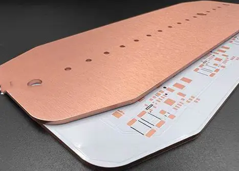
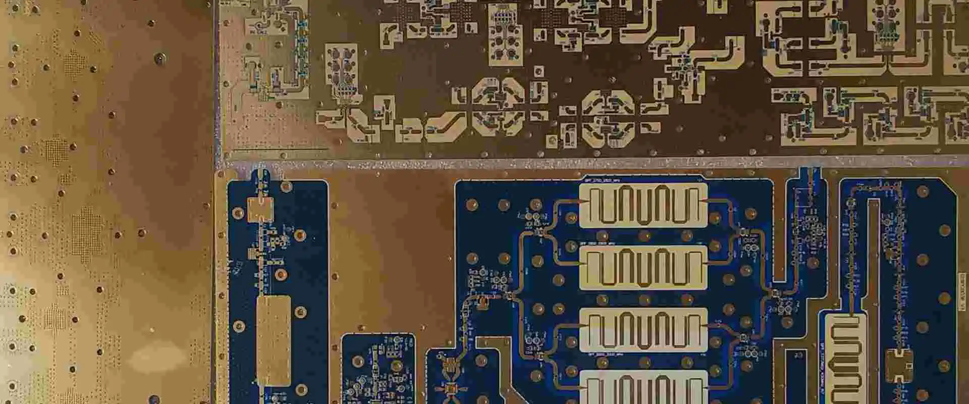
Copper is a core material used in PCB manufacturing. Printed circuit boards are available in most electronic devices. Also, they provide connection to various electronic components. Also, copper circuit boards provide the conductivity and durability needed for high-temperature applications. A bare copper PCB integrates copper as its base layer. This article aims to provide further details about bare copper PCBs and their functions.
What is a Bare Copper PCB?
A bare copper PCB is a metal core PCB which features copper as its base layer. Also, this type of circuit board integrates bare copper. Bare copper has unparalleled conductive properties. It can be medium-hard, soft, or hard. A bare copper PCB features higher thermal conductivity than other metal core PCBs.
Furthermore, there is an even transfer of heat through a bare copper board. Even transfer of heat is crucial because lack of it can put too much stress on the circuit board. Also, copper features exceptional electric conductivity which enables it transfer signals with less electrical energy loss.
Bare copper PCBs offer excellent performance when used in different applications and industries. A bare copper has no coating. Therefore, a bare copper PCB features copper that has no coating. The type of application will determine the use of bare copper PCBs. A bare copper PCB is highly preferred because of its high tensile strength.
Copper is well known as a good conductor of electricity. This material features a high thermal conductivity. There are several benefits of a bare copper PCB which includes:
Exceptional thermal conductivity
Bare copper features very exceptional thermal conductivity. The high thermal conductivity of this PCB allows it to transfer and dissipate heat at a much faster rate. Standard PCBs like FR-4 may not be able to withstand heat in some environments. Therefore, a bare copper PCB is an ideal choice for such application environments. This PCB transfers heat from crucial circuits and prevent any performance issues.
Durability
Bare copper boards are less likely to corrode over time. Therefore, this makes them more durable. Also, bare copper can withstand the manufacturing process much better than standard materials can. Therefore, this helps to minimize breaks that may likely occur during development.
Reduces assembly costs
Bare copper boards don’t require a lot to assemble. With these boards, PCB manufacturer don’t need to install heat sinks on PCB surface. This is because bare copper boards dissipate heat at faster rates, so, they don’t need heat sinks.
Environmental friendly
Copper is recyclable. Therefore, it is friendly to the environment. Copper doesn’t cause harm to the environment and human lives. The integration of a bare copper PCB makes your project environmental friendly.
Enhances electronics’ reliability
Bare copper features an unparalleled thermal resistance. This helps to enhance the electronic devices’ reliability when used in harsh environments.
Bare copper PCBs are suitable for high-power applications. Also, these PCBs offer the highest level of thermal conductivity. These PCBs can survive several severe conditions without any damage to the crucial components. Bare copper boards are crucial in light-emitting diode (LED) applications. These boards play a significant role in their performance.
Also, bare copper boards enable you to achieve more complex projects. These boards also support high-density designs. Therefore, what are the possible applications of these boards?
Light emitting diodes
The rapid advancement in LED technology has raised many concerns about heat dissipation. LEDs are always mounted on the circuit board. They can cause reliability and stability problems for a printed circuit board when the right technique isn’t adopted. The use of bare copper PCBs is an ideal option for these applications. Bare copper boards are widely found in interior lightings, street lights, and more.
A bare copper PCB is ideal for use in consumer electronics like televisions, computers, etc. Also, these circuit boards offer great thermal conductivity and heat dissipation. Therefore, they enhance the performance of these consumer electronics.
This board is available in power rectifiers, solid-state relays, and bridges. Also, a bare copper PCB is ideal for these type of applications because they demand a lot of energy and generate much heat.
Medical devices
Bare copper PCBs are also suitable for use in medical devices. You will find these boards in high-power scanning technology, power converters, operating room and surgical lighting.
Bare copper boards can corrode or oxidize. This can affect the performance of these boards. Here are simple ways to protect your bare copper PCB from oxidation and corrosion.
Your bare copper board will come in a vacuum seal once you receive it from your manufacturer. This seal prevents this board from moisture and humidity. Ensure you keep this board in a container free of humidity once they are removed from the packaging.
Keep your PCBs away from corrosive metals
Ensure your boards don’t come in contact with corrosive metals. For instance, keep bare copper boards very close to aluminum can result in oxidation.
Request for a finish
One of the best ways to preserve your bare copper PCB is to request for a protective layer. This layer covers the copper and as such, serves as a form of protection to your board.
Use hermatic sealed packaging
Hermatic sealed packages protect your bare copper boards from environmental conditions. However, hermatic sealing needs to be carefully carried out in a controlled environment. Also, hermatic seal can prevent moisture from trapping in the packaging.
Conformal coating is a good way to protect your board before using it in any electronic device. Also, this coating prevents your board from corroding and oxidizing.
Conclusion
Bare copper PCBs offer a lot of benefits when used in some applications. Also, these circuit boards are ideal for high-performance applications as they offer great thermal conductivity and heat dissipation. Bare copper PCBs are a good choice for several applications. Experience the benefits of this board by integrating it in your PCB projects.
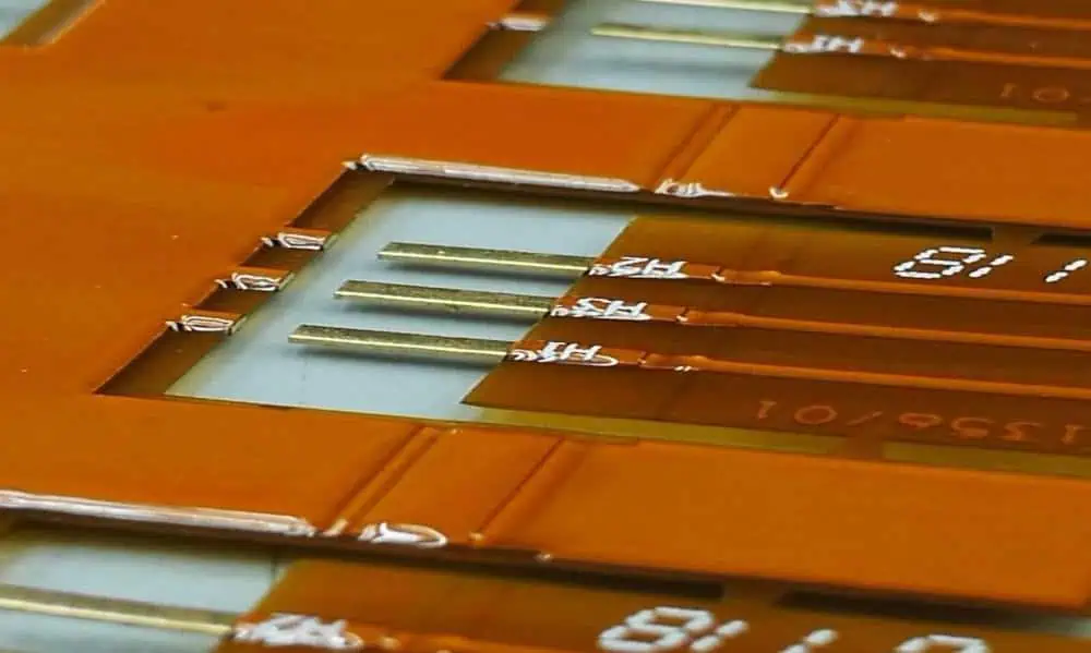
Flexible printed circuit (FPC) has been designed to meet the demands of the market. Some wearable devices or mobile devices require high current draw functions like brighter displays. This trend will continue. Therefore, this need isn’t in line with the drive towards devices that are becoming lighter and thinner every year. Also, batteries must be lighter and smaller as well.
Therefore, the connector between the circuit board and battery must be small, but must be able to conduct greater currents. In this article, our primary focus is on battery FPC.
The flexible printed circuit (FPC) ultrathin lithium ceramic battery is designed in a way that it breaks through the procedures of traditional lithium batteries. Battery FPC integrates a flexible circuit board as a packaging material and base material. The ultrathin battery is small. Therefore, it is easy to carry. Also, this battery is safe, hence, it can’t cause any explosion, fire, or combustion.
Also, this battery can withstand high temperature, physical impact, and low temperature. Battery FPC is very easy to assemble and it can be connected with a circuit board. Also, this battery features a flexibility radius that ranges between 15-17mm. This battery can’t cause explosion or fire even after exposing it to overcharge testing via ultrahigh external voltage.
A battery FPC serves as a protection to the lithium-ion battery pack. Also, FPC which means flexible printed circuit is a type of protection circuit module. Furthermore, an FPC is ideal for use in flexible devices. You will find them in wearables such as medical monitoring devices and smartwatches. These devices integrate lithium polymer.
A flexible printed circuit comprises a base film and several wires created on the base film. The battery FPC is very easy to carry. When tested by varying temperature, physical impact and electrically damage test, this battery can’t cause leakage, explosion, or fire.
Therefore, it serves a battery connector in tablets, smartphones, and some wearable devices. FPCs are ideal for use in near field communication (NFC) devices. Also, the NFC chip usually comes with the battery since it is a suitable location to communicate from.
The production process of FPCs involves grafting on a flexible copper clad and cutting into different sizes of layers.
This battery features high retention force despite being small and having a thin profile. Therefore, this contributes to the performance of these batteries when used in devices. Also, a battery FPC can retain stored energy for a longer period.
High connection reliability
Despite its thin profile, this battery connector offers high connection reliability. This makes it ideal as a battery connector for mobile devices.
High assembly efficiency
This battery realizes high assembly efficiency with ease of positioning when attaching the socket to header.
What are the Differences Between FFC and FPC?
Most times, people interchange FPC for FFC. These two terms are used interchangeably in the PCB industry. Although FPC and FFC provide advanced features, they are entirely different. So, how do you distinguish between FPC and FFC connectors?
Well, the first difference is in their meaning. FPC means flexible printed circuit while FFC means flexible flat cable. Also, FFC is a type of cable that is flat and flexible while FPC is a flexible printed circuit. FFC connectors are films with metallic termination that is parallel to the foundation. FPC comprises inserted or printed circuitry on the FPC cable board.
FFC and FPC play different roles. FFC cables are extensively integrated for high flex applications. Also, FPC is available in LCD, antennas, printers, etc. Over the years, FPCs have developed. In terms of their manufacturing process, FPCs are different form FFCs. The production process of FPCs involves grafting on a flexible copper clad and cutting into different sizes of layers.
On the other hand FFC involves a lamination of flat PET and copper wires. This is the reason behind its extra thickness. also, FFCs are specially made with layers of wires. Also, there is a difference between these connectors in terms of their thicknesses.
The suitable thickness of FFC ranges between 0.5mm and 2.54mm. Meanwhile, the thickness of FPC cables range between 0.15mm and 0.2mm. Furthermore, the manufacturing strategies of FFCs are very classified. In contrast, FFCs are a bit vulnerable. FFCs comprise highly conductive components. Therefore, with these differences, these connectors can’t replace each other.
The FPC connector connects printed circuit boards and flexible printed circuits. One of the ways to connect FPCs is by inserting them directly in the connector. Also, it is possible to connect them with flexible flat cable (FFC).
The FPC connector connects printed circuit boards and flexible printed circuits. There are three crucial parts of an FPC connector. These include:
Terminal
The terminal ensures a stable contact performance. It integrates a narrow contact method to achieve this. Furthermore, it selects the material with great mechanical properties.
Plastic body
This is a sheet-like barrier framework you can organize after installation. Also, this provides a certain stabilization force. The plastic body needs to be rigid and string based on the specifications of the application. Also, there must not be any wrap deflection throughout the soldering of SMT.
Card lock
The fastening parts help to lock the FFC/FPC in order to preserve a certain contact force when implanting the FPC/FFC. Therefore, the parts must be rigid.
Frequently Asked Questions
What are the applications of FPC connectors?
FPC connectors are widely used in handy terminals, industrial robots, smart meters, and semiconductor production equipment.
What are the types of FPC connectors?
There are several types of FPC connectors. They include flexible multilayer circuits, single layer circuits, and two-sided layers.
Conclusion
The major application of a battery FPC is its connection in smartphones and some wearable devices that integrate embedded batteries. The connector between a PCB and battery must be able to conduct greater currents. Also, a battery FPC maintains a thin profile and a high retention force. Also, this battery features 6 A current capability.
The electronic components industry is global in scope and has significant growth prospects. The growing market for mobile devices and industrial automation is driving growth. International subscribers to smartphones will exceed 6.0 billion by 2021.
The growing smartphone penetration and the adoption of electric vehicles drive the growth potential. In addition, the Asia-Pacific region has a large pool of cheap labor and is home to some of the world’s largest electronics manufacturers.
The emergence of Industry 4.0 and the rise of Industrial IoT fuel demand for general electronic components. These components are helpful in smart devices, sensors, and actuators. According to Juniper Research, the global market for IoT components will reach $344.7 billion by 2026.
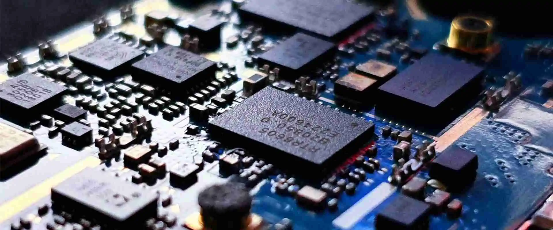
The electronic components manufacturers include the manufacturing of semiconductors and other electronic components. These components are helpful in various electronic devices, including mobile phones, computers, and appliances.
Generally, we can divide the market for these components into active, passive, and electro-mechanic components. The former has the largest market share, followed by passive and electro-mechanic components.
Despite the challenges in the industry, the electronics sector is continuing to grow, largely thanks to increased consumer spending in emerging markets. However, as the landscape shifts and new technologies emerge, the industry will likely become more competitive and fragmented. Consequently, the stock prices of electronics manufacturers will fluctuate.
Electronic components manufacturers are a critical component of the manufacturing facilities and process of electronic devices. They design and develop the components needed for a specific device and the assembly process.
They then package and ship the final product to retailers and consumers. Some electronics manufacturers are environmentally conscious, and some use solar power to run their operations.
The electronic components manufacturers produce electronics for many different types of companies. Whether the manufacturer is an OEM or an EMS provider, they can offer modern fast, flexible production lines to create the final product. Working with a third party includes lowering fixed costs and headaches. The services of a third-party manufacturer are more flexible and cost-effective.
Electronic manufacturing companies are important partners for OEMs because they provide expert assistance in assembly and supply chain management. They can produce printed circuit boards, electronic modules, and entire devices.
These services are vital to the success of many successful products. Electronic manufacturing companies provide a critical component of the supply chain and are essential to the success of an OEM.
An EMS is a contract manufacturer that provides manufacturing services for products from various industries. These companies are responsible for sourcing components and raw materials worldwide. They also help customers troubleshoot and repair electronic products. Some of these companies even offer after-sales services.
Manufacturing electronics is a global industry with significant global impact. About half of the electronics components manufacturers distribute their products overseas, nearly double the percentage of all US manufacturing.
Additionally, 26% of electronics components manufacturers import raw materials, compared to just 11% of US manufacturing. In Redondo Beach, California, Northrop Grumman Aerospace International, Inc. employs more than 10,000 people and is one of the world’s largest consumer electronics manufacturers. The company’s products range from wireless devices to satellites to space exploration.
The supply chain has long relied on the just-in-time build-to-order pipeline model. However, this model can handle sudden increases in demand for consumer electronics. Unfortunately, the coronavirus outbreak in China in 2018 hampered the electronic component supply chain by disrupting production capacity.
The virus spread through Wuhan, China, a hub of mechanical and electronics suppliers. As a result, factories could not produce at full capacity, making it impossible to meet demand.
Electronic components manufacturers should focus on collaboration with electronics suppliers. While a single supplier can provide some components a company needs, a multi-supplier approach can help ensure better supply stability.
By collaborating with multiple electronics suppliers, companies can minimize the risk of supply shortages and increase their competitive edge. Ultimately, they can avoid the risks and expenses of dealing with one supplier alone.
An electronic component is a discrete device that affects electrons and their associated fields. They are generally industrial equipment and come in single or plural forms. These components can be electrical components, diodes, resistors, or microprocessors. You can also look at them as conceptual abstractions of idealized electronic components.
Diodes
A diode is a semiconductor device that is helpful in electronic circuits. They are commonly essential in rectifying circuits. They are made up of at least two terminals and need an external supply for operation.
The diode has fixed polarity and is primarily necessary for rectifier circuits. A transistor is another semiconductor device with at least three terminals. Its function is to amplify the electrical current.
The first of these components is a point-contact diode, developed in the 1930s out of crystal detector technology. It uses a small diameter metal wire in contact with a semiconductor crystal.
There are two types of point-contact diodes: welded and non-welded. The former uses the Schottky barrier principle to switch an electrical current; the latter forms a small P region surrounding a metal point during manufacturing.
The reverse recovery time of a diode is typically negligible, although it can cause a significant reverse current. The operating circuit and the series resistance determine the magnitude of this effect.
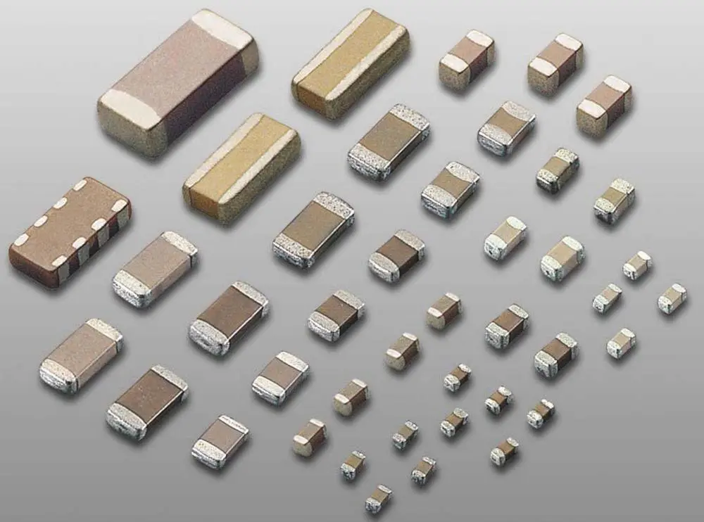
Resistors
Resistors are electronic components that can be helpful in a variety of applications. Some common uses include voltage dividers, current limiters, pull-up resistors, and filtering. Other uses include voltage feedback circuits and voltage references.
When selecting the right resistor for your application, you need to consider several factors, including the component type and its tolerance. Also, consider the real estate available on your printed circuit boards.
Resistors are also helpful in combination with capacitors. The two are often combined to create a device that suppresses electromagnetic and radio interference. These devices are available in machines, automatic equipment, elevators, and switcher-motor controllers. They are also helpful in circuits where high-frequency voltage is needed.
Another common application for resistors is in volume control. The variable resistor (also called a potentiometer) has a continuous resistive material, and its contacts traverse it in a straight or circular path. They usually are adjustable with a screwdriver or adjustment tool.
To create successful electrical and electronic products, you need to understand the types of electronic components. The following list will help you to understand the components you will need to make your electronic products. You should also stock your workspace with the right tools and materials. However, the list may not include every item that you may need.
Electronic components have two basic types: active and passive. An active component amplifies and stores an electric charge, while a passive component has no active function.
Active components are often used as circuits to produce alternating currents, and their functions are varied. For example, a diode is a semiconductor device that acts as a one-way switch for current but can also be reverse-biased.
Transistors are another component type used in electronic circuits. They are semiconductor devices that change electrical power supplies and amplify electronic signals.
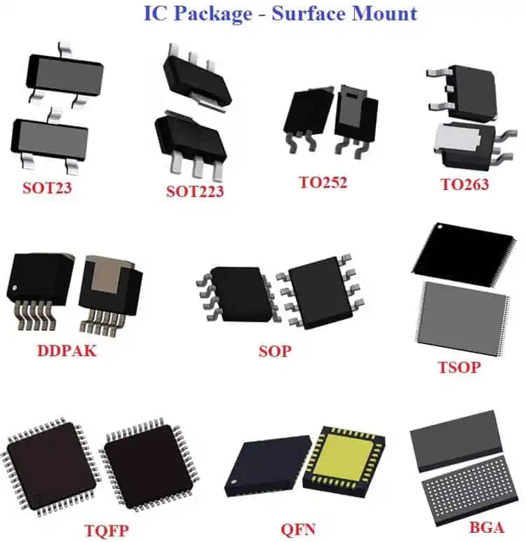
Integrated circuits
An integrated circuit is a micro-electronic device composed of several components linked together. It is typically made from a semiconductor wafer and can perform many functions.
It is one of the four basic types of electronic components. Some common examples include a microcontroller, amplifier, timer, counter, and logic gate.
ICs are widely essential in electronic devices, from toasters to automobiles. They are also helpful in amusement park rides. Because of their small size, ICs have improved functionality and power consumption. They also have fewer parts, which makes them more flexible and easier to replace.
Integrated circuits can be analog, digital, or mixed-signal. Analog ICs process analog signals and have a linear relationship between the input and the output signal.
Examples of analog ICs include transistors, operational amplifiers, and differential amplifiers. Digital ICs, on the other hand, process digital signals. They are ideal for digital televisions, 3G mobile phones, and digital cameras.
Electronic components are an essential part of any electronic system. They change the flow of electric current to transmit information. The essential components include diodes, transistors, and capacitors. Understanding the basics of these components is vital to understanding how they work. There are millions of different types of semiconductors used in electronic devices.
Diodes are semiconductors that allow an electric current to flow in one direction. They have two terminals: an anode and a cathode. Electric current flows through the anode when a positive voltage is applied, while negative voltage flows through the cathode.
On the other hand, transistors have three terminals: a base, an emitter, and a collector. They operate by applying a voltage to the base terminal, allowing them to control the current flow in the emitter and collector.
When it comes to the components, there are two types: passive and active. Passive components are those that are dependent upon a power source, while active components are those that process signals and provide energy.
Examples of active components are transistors, ICs, and tunnel diodes. These are all components that will be helpful in electronic circuits. Regarding the electrical components, there are several different types of resistors. The most basic type is the resistor, a copper wire wrapped around a ceramic rod.
Its capacity depends on the number of turns around the copper wire: the more turns, the more excellent the resistance. So, for example, a thicker wire has fewer turns, while a thin copper wire has more turns.
Other types of components are helpful in electronics. For example, an inductor is a device that stores energy by creating a magnetic field around a core. An inductor consists of a wire coil wound around a metal core, but it can also consist of air.
Digital signal processing is a way of processing signals digitally. It can be performed by specialized digital signal processors or by computers. It can perform a wide range of signal processing operations. Some of the most common digital signal processing applications include audio and video recording. However, the applications are as varied as the hardware used to perform these processes.
Digital signal processing uses a processing engine called a digital signal processor (DSP). This computer may be a general-purpose processor, FPGA, or a dedicated DSP chip. Each of these processors has its advantages and disadvantages.
However, these processors provide powerful algorithms and efficient computational abilities. For example, a DSP chip can process audio signals at a higher bitrate than an analog processor.
A digital signal processor allows signals to compress and enhance, which allows them to be transmitted quickly. It can also improve their quality, making them more useful for many applications. The technology is even used in medical imaging to create computer-enhanced images.
DSP chips depend on a combination of hardware and software architecture. In addition, DSPs feature memory architectures specifically designed for real-time data streams.
This enables them to process audio and other data types more quickly than conventional CPUs. As these benefits become more widely recognized, high-profile companies are using DSPs to develop new audio products.
There are several types of electronics manufacturers. Some specialize in one particular field, while others cover multiple disciplines. These include Microelectronics, Optoelectronics, System assembly manufacturing, and Semiconductor supply and manufacturing services. Each type has unique strengths and needs and offers services in various areas.
Microelectronics
Microelectronics manufacturing requires good eyesight, steady hands, and experience disassembling electronic devices. It is not physically demanding, but the work can be very tiring for the eyes and back. Older people may have difficulty with this type of work. There are several different levels of training for this field.
A microelectronics manufacturer can work alone or with a team in a factory. Therefore, jobs in this field tend to be more plentiful in large cities. However, smaller cities may also have opportunities. For example, the small town of Waterloo, Ontario, has several electronics companies.
Developing a domestic semiconductor industry requires a lot of planning and focused effort. However, if successful, it can make the United States a more prosperous nation. In addition to making the United States more competitive, the transition will require significant funding.
Optoelectronics
Optoelectronics is a field that bridges the gap between electronics and optics. The field involves designing, studying, and manufacturing hardware devices that transform light into electrical energy. Therefore, we can segment the optoelectronics market according to component type, application, and geography.
The most common type of optoelectronic component is a laser diode. They are fiber optic communication, laser light sources, bar code readers, and DVD players. The industry will grow in the coming years as the need for these devices continues to increase.
System assembly manufacturing
System assembly manufacturing (EMS) involves assembling components that form product electronics. This type of manufacturing can be done in-house or outsourced to a third party.
Companies specializing in this type of manufacturing may specialize in high-volume, high-mix products, or both. In addition, some companies specialize in one or several markets, such as consumer electronics, machinery, or medical equipment.
EMS providers often provide a full suite of electronic manufacturing facilities and services, from design to testing and manufacturing. Some may even provide additional services, including product development and supply chain management.
While many OEMs choose to handle their manufacturing, other companies prefer to outsource the process to a third party. Outsourcing the electronics assembly process to a domestic EMS provider is an excellent idea, particularly during product development.
Domestic EMS partners will generally have shorter turnaround times and will ensure that your product meets industry standards. Furthermore, domestic EMS partners understand the unique needs of your project, which can help reduce the time from design to production.
Key Facts and Statistics on the US Electronics Components Industry
While the electronics components industry has faced many challenges, it has flourished. With strong sales and distribution globally, the US electronic components industry has seen a 1% increase in employment over the past year.
And it is expected to grow to $306 billion by 2022. According to MNI, the electronics component industry has many opportunities for companies and distributors of electronic components.
Effects of the pandemic
During the pandemic, the supply crisis led electronic components manufacturers to prioritize parts needed for the healthcare industry. As a result, demand for ventilators and other medical devices increased, and components manufacturers contributed to lifesaving efforts. When manufacturing resumed after the pandemic, however, the shortages of these parts remained.
The semiconductor industry drives the electronics industry. As of 2018, this industry generated $481 billion in sales. Meanwhile, e-commerce generated over $29 trillion in 2017.
The metal-oxide-semiconductor field-effect transistor was invented in 1959 and continues to drive the electronics industry.
Electronic Components Industry Association (ECIA) is a trade association comprised of leading electronic components manufacturers, authorized distributors, and technology companies.
The organization’s mission is to advance the electronics components industry. In this way, it supports business optimization and develops technical standards. Furthermore, it generates vital business intelligence.
Consumer electronics devices have become increasingly popular and widely used. For example, television sets are getting smaller in size and more convenient. In addition, the miniaturization of electrical components is increasing. Therefore, the demand for these products will continue to grow in the coming years.
According to the Consumer Electronics Association (CEA), the average American household utilizes approximately 28 electronic items. This includes televisions, mobile phones, personal computers, and electronic readers. This report also indicates the EPA’s “Waste Management Hierarchy,” which lists management strategies according to their environmental impact.
North America holds a majority of the market for electronics components. Demand for speakers, monitors, and wearables is increasing in the region. Moreover, gaming is a significant consumer trend in North America. According to the Consumer Technology Association, by 2020, the US population will spend an average of USD 528 on technology items.
Semiconductor manufacturing is a complex process that includes chip design, fabrication, assembly, testing, and packaging. Today, the United States employs 184,600 people directly in the semiconductor manufacturing industry.
However, this sector only accounts for a small portion of the world’s semiconductor fabrication capacity. As a result, this industry faces threats ranging from intellectual property theft to product tampering. It also faces challenges related to technology transfer pressures.
As a result, demand for semiconductor parts has soared. Originally, chipmakers were unable to meet the demand. However, the shortage has forced the electronics industry to rethink its supply chain management.
As a result, electronics manufacturing service companies are at the center of the multidirectional supply chain, making goods for a wide range of companies, including original equipment manufacturers (OEMs).
The semiconductor industry will likely expand beyond centralized processing units to incorporate new technologies. For example, the future of semiconductors relies on devices that can operate at higher voltages, frequencies, and temperatures. As these developments continue, companies like PowerAmerica are developing new types of semiconductors.
As technology progresses and the number of devices that utilize electronic components increases, the need for reliable components grows. New technologies, such as the Internet of Things, are creating new applications for electronic systems. This means that electronic components manufacturers face greater challenges in meeting demand and production timelines. This, in turn, increases lead times and reduces stock availability, affecting all manufacturers. As a result, manufacturers are considering new materials and technologies to meet demand.
Reliability
Luckily, there are several sources to find a reliable electronic components manufacturer. One of these resources is Sourcengine, an e-commerce marketplace for the electronics parts industry. This site provides procurement specialists with an index of the leading electronic part manufacturers in the industry. Clicking on a manufacturer’s name provides more information about the company and its factory-direct offerings. This directory also lists the most popular parts from each manufacturer.
Revenue
Electronic components manufacturers often rank based on their revenues. For example, the largest electronic components manufacturers in the current list have the highest revenue. However, it is essential to note that many of the electronic components manufacturers are in varying stages of growth. For example, the first EMS, Deki Electronics Ltd, increased its revenues by more than double the previous year. Other high-growth EMSs include Globe Capacitors Ltd. Conversely, the lowest-growth companies are small but generate significant revenues.
Quantity
Distributors are a vital part of the supply chain for electronic components. Their services help electronic components manufacturers and development organizations buy the right quantity at the right time. Moreover, distributors can also help them introduce new components into the market. A lot of electronic components manufacturers have processes in place to ensure quality. This is important when new components enter the market.
Some electronic components manufacturers also provide design and development services. Some of these providers specialize in analog, digital, and RF microcircuits. These companies can even re-engineer parts from other semiconductor companies. In addition, these manufacturers offer various options, from custom-designed power converters to flat packs, RF connectors, and other products and services.
Workforce
Although the number of employees in the industry has declined significantly, there has been an increase in the number of global markets and e-commerce. In addition, many leading global electronic components manufacturers are merging with companies based in the US. The decline in employment also has been attributed to increased automation.
Some of the biggest electronic component manufacturers include Samsung, based in South Korea. The company is a leader in manufacturing memory chips and other types of semiconductors. Its products are helpful in many different applications and industries. Its headquarters in the United States employs over 70,000 people. Moreover, it also has manufacturing bases in Vietnam and China.
In Vietnam, electronic components manufacturers include ABECO Electronic Equipment Vietnam Co., Ltd. The company has been manufacturing electronic components for almost 47 years. Its products include electrolytic capacitors and a variety of other types. In addition to making electronic components, the company produces auto parts.
Top Electronic Companies in the USA and Global Electronic Component Suppliers
You should be aware of a few big names in electronics manufacturing. These include Intel, Toshiba, Royal Philips, and Dell Technologies. Each of them provides different services and products. But what sets them apart? First, read on to learn more about them. Then, we will discuss their business’s various aspects and roles in the global electronics industry.
The USA is home to hundreds of electronics companies. These companies range from chip makers to infrastructure services. Some leading companies in this market include IBM and Cisco, which specialize in networking and semiconductor products. Other companies that manufacture and supply electronic products include TI and Intel. Intel, for instance, is the world’s leading international manufacturer.
Some of the largest electronics companies in the world are in the USA. These companies are well-known in specific industries and take pride in their products. When selecting a manufacturer, it’s essential to ask them about their experience and previous work plans and inquire about their fees and guarantees. Then, check out their package offerings.
Several associations help electronic companies in the USA promote their products. One such organization is the Consumer Electronics Association, which organizes events and provides information for industry professionals.
Another group, the International Electrotechnical Commission, is a global association that creates standards for different types of electronic products. These standards help to ensure that products are safe for consumers.
Dell Technologies
Dell Technologies is committed to minimizing its environmental impact as one of the leading electronics companies in the USA and global electronic component suppliers. The company’s efforts to save energy and water show this commitment to the environment.
Dell’s efforts have helped reduce its global absolute GHG emissions by 38% and save more than 1.2 million cubic meters of freshwater in the last fiscal year. In addition, the company’s Plant a Tree program has helped plant more than 1.6 million trees since 2007.
Dell has a diverse clientele and a significant presence in various markets. These clients represent different age groups and financial capabilities. The company also aims to serve various markets and appeal to various demographics.
Dell is well-positioned to serve a broad range of clients by being an electronic component supplier and computer manufacturer.
The electronics industry is an industry that continues to grow at stellar rates. While the United States dominates the global market, many multinational companies compete for a share. For example, TE Connectivity, based in Switzerland, is the largest electronics company in the world. The market capitalization of TE Connectivity is higher than that of Amphenol Corporation.
Royal Philips
Philips Electronics North America aims to be in the top three companies in the communications industry in the United States by 2000. This goal is partly achieved by developing new products like WebTV and acquiring other companies, such as Oracle InterOffice e-mail and Magnavox.
The company also sees opportunities in name recognition and increasing customer volume. For example, in 1996, Philips introduced the Philips Magnavox WebTV, a TV set that used a telephone to access the Internet. This product can reach a large segment of households without computers.
Philips has many divisions and manufacturing subsidiaries around the world. The electronic components manufacturers produce consumer and industrial electronics, semiconductors, and diagnostic imaging systems. Its products compete with Sony, Samsung, HP, Dell, Toshiba, and other companies. It also produces medical systems and lighting technologies.
Top Electronic Companies in the USA and Global Electronic Composition Suppliers are excellent sources for semiconductor electronic components. They carry the most popular brands and some that are harder to find. Whether you need a single component or an entire printed circuit board, they can help.
The companies have millions of satisfied customers and serve a variety of industries. These companies have a solid reputation for competitive pricing and unsurpassed customer service. Hobbyists can also get their electronics supplies from them.
Those looking for a manufacturer should start by researching the company’s experience. Well-established companies often specialize in a particular industry and take great pride in the quality of their products. Look for information about their past work plans, guarantees, fees, and package offerings.
Some leading electronic companies in the USA include TI, IBM, and Cisco. These electronic components manufacturers specialize in semiconductor and networking products and services, infrastructure services, and hosting services.
IEC Electronics Corporation
Founded in 1967, IEC Electronics Corporation focuses on electronic contract manufacturing services, circuit protection devices, circuit cards, and wires and cable loads. The company has over 1,300 employees and utilizes the latest technology to produce electronic products. The company achieved profitability in its first two years.
By fiscal 1976, revenues had reached $4.06 million. After this, the company entered the consumer electronics market, manufacturing VHF and UHF portable radio transceivers and paging receivers. Its customers include a variety of major U.S. and global companies.
Despite challenges, IEC has managed to grow its business by leveraging its supply chain and implementing new technologies. For example, it has implemented a new tool called Parts
Intelligence, which puts component pricing from more than 2,000 manufacturers at the fingertips of IEC staff. The tool allows IEC staff to respond quickly to RFPs within 72 hours instead of one or two weeks. In addition, IEC has integrated the IHS Markit tools into its IT systems, dramatically improving its efficiency in executing its processes.
Today, IEC Electronics Corporation is a global electronic component supplier and manufacturer. Its products are widely helpful in consumer products, industrial and laboratory devices, and military equipment.
Other leading US electronic companies include Texas Instruments Corporation (TI), the world’s second-largest revenue-generating company and one of the leading suppliers of semiconductor products.
Amphenol Corporation
Amphenol Corporation is one of the world’s leading electronic components manufacturers and suppliers of electrical components and electronic components. The company’s products manufacture various electronic components, from sensors to antennas.
The company is also one of the leading suppliers of coaxial and high-speed specialty cables. Amphenol Corporation was established in 1942 and is in Chicago, Illinois. The company began producing electronic components in Chicago, Illinois, Connecticut, and California.
By 1956, Amphenol was reporting annual sales of $27.3 million and was trading on the New York Stock Exchange. The same year, the company bought another called the Sine Companies, which produced connectors for industrial and commercial markets. The acquisition helped the company increase its sales and earnings.
During the 1990s, Amphenol diversified its operations by establishing R&D facilities in Asia. In January 1997, it acquired the 51 percent stake of Kai-Jack Industrial Co. Ltd. The company also expanded its manufacturing operations in China, Mexico, and Brazil. In addition, the company expanded its global presence in the following years by acquiring various companies in different markets.
Cherry Semiconductor Corporation is one of America’s leading electronic component suppliers. Founded in 1957, Cherry has become one of the world’s largest electronics companies. The company has approximately 3,800 employees in the greater China region and operates 30 sales offices in the Asia Pacific.
Cherry’s product portfolio includes passive and discrete electronic components. They sell their products to electronics OEMs in global markets. Its products include resistors, capacitors, potentiometers, connectors, and magnetic and circuit protection components.
Cherry has expanded through acquisitions and continues growing as a global electronic component supplier. It is a leading provider of precision electronic interconnect components, precision stampings, and more.
Its products have an extensive range and are sold to millions of engineers worldwide. In addition, its memory products are helpful in almost every type of device, from MP3 players to digital cameras.
Cherry Semiconductor Corporation’s diverse portfolio includes automotive, medical, industrial, and consumer electronics. The company has shipped over 25 million PSD MCU peripherals to customers worldwide. It supports more than 1,100 applications.
Dolby Laboratories
The company’s technologies are essential in televisions, set-top boxes, and other devices. Consumers use these products to enhance the sound quality of movies.
Dolby has also licensed its technology to companies to help them reduce audio noise. In addition, the company’s products are ideal for computers, mobile phones, and other devices.
Dolby Laboratories specializes in designing and manufacturing high-quality audio and imaging products. Their products help consumers enhance sound, image, and transmission quality. They also develop three-dimensional glasses, broadcast hardware, and accessibility solutions.
Dolby technology is essential in TV sets, home theaters, and mobile phones. Its product portfolio includes Dolby Digital, Dolby Pro Logic, and Dolby TrueHD. Dolby has also developed surround sound technology for mobile phones.
Texas Instruments
Texas Instruments Incorporated company designs semiconductors and various integrated circuits for electronic devices. They sell their products to electronics companies around the world.
In addition, its products are widely helpful in personal computers and other digital devices. Its mission is to provide customers with the most advanced, reliable, and efficient electronic components.
Texas Instruments has a long and rich history in the semiconductor industry. Its employees have seen the rise and fall of the industry, and it can help younger semiconductor entrepreneurs avoid making the same mistakes.
In addition, the company has a division that serves the oilfield seismic exploration market. Its products helped engineers better understand the nature of these waves. As a result, despite the high cost of production, Texas Instruments can make a profit margin of 50%.
The company has been around for over 70 years and has a long history of innovation. In 1954, Texas Instruments created the world’s first transistor radio.
The device was called the Regency TR-1 and used germanium transistors. However, these were much more expensive than silicon transistors. So Haggerty wanted to create a more affordable transistor to increase the market’s demand.
Texas Instruments is a pioneer in the semiconductor industry. Its semiconductors are helpful in industrial machinery and vehicles. The company has a worldwide presence and is the world’s leading manufacturer of semiconductors.
TE Connectivity is an American technology company that designs sensors and connectors. The company makes these products for various industries, including automotive, industrial equipment, data communication systems, medical devices, and consumer electronics. In addition, TE Connectivity also designs sensors for the energy, medical, oil, and gas industries.
TE Connectivity is one of the largest electronic components manufacturers of sensor and connector solutions. It sells its products in over 140 countries. The company was known as Tyco Electronics Ltd. and changed its name in March 2011. Its headquarters is in Schaffhausen, Switzerland.
In addition to providing sensor and connector solutions, TE Connectivity supplies industrial products for power supplies, data, and signals. Its products are widely helpful in factory automation, security, and robotics.
Other applications include elevators, high-speed trains, locomotives, and the solar industry. These products also enable the Internet of Things to function properly.
Summary
The Circuit Board and Electric Component Manufacturing industry produces the plastics and electrical components essential to producing electronic equipment. The production of downstream products typically influences demand for these components.
For example, continued economic growth has increased consumer demand for electronic items, while offshoring activities have decreased domestic production.
The healthcare industry continues to be a significant focus for electronic components manufacturers. For example, as the need for ventilators increases worldwide, electronic components manufacturers contribute to lifesaving efforts.
In addition, IoT devices are helpful for inpatient monitoring and remote patient monitoring. These innovations are creating new business opportunities for OEMs throughout the world.
Despite this, the semiconductor industry is still facing challenges. The supply of semiconductors has become increasingly limited, while the demand for these products has increased. The shortage of components has led to price hikes and longer lead times.
In addition, the growth of e-commerce has resulted in a significant spike in demand and strained supply, resulting in higher prices and longer lead times. In addition, the semiconductor ecosystem continues to be affected by virus outbreaks and government regulations that create labor shortages.
While no single component guarantees a continuous supply of products, there are several ways to avoid these interruptions. One way to do this is to implement a supply chain strategy that protects operations from disruptions.
This includes developing a sourcing plan and building relationships with suppliers. In addition, it is crucial to consider the global footprint of your suppliers and the ability to source more diverse parts from multiple sources.
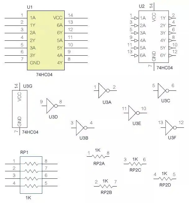
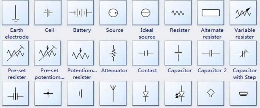
Electrical and electronic symbols are graphical representations of electrical and electronic components and devices used in circuit diagrams. They allow for the visual communication of complex circuit and wiring information in a standardized way. This article will provide a full introduction to the most common electrical and electronic symbols, their meanings and applications.
Overview of Electrical and Electronic Symbols
Electrical symbols represent items such as batteries, wires, resistors, inductors, switches, transformers, transmitters, receivers, meters, and capacitors. Electronic symbols represent electronic devices and components in circuits including diodes, transistors, integrated circuits, and logic gates.
Standardized sets of symbols ensure that anyone reading a circuit diagram can understand the circuit and how it functions regardless of language or location. Using clear, universally recognized symbols improves communication and avoids errors arising from misunderstandings.
There are different standards for electrical and electronic symbols, but the International Electrotechnical Commission’s (IEC) standards are the most widely adopted worldwide. The IEC 60617 standard covers graphical symbols for diagrams, while the IEC 617-12 standard specifically covers symbols and designations for semiconductor devices.
In the United States, the American National Standards Institute (ANSI) also publishes guidelines on electrical and electronics symbols and how they should be used. While less common globally, ANSI standards are still important for electrical work in the US.
Loudspeaker – Converts electrical energy to sound.
Thermocouple – Converts temperature to electrical voltage.
Ammeter – Measures electric current.
Logic Gate Symbols
AND Gate – High output only if all inputs are high.
OR Gate – High output if any input is high.
NOT Gate – Inverts input signal.
XOR Gate – High output if inputs differ.
Transistor Symbols
NPN Bipolar Junction Transistor – NPN transistor allows current flow when base is active.
PNP Bipolar Junction Transistor – PNP transistor blocks current flow unless base is active.
N-Channel JFET – N-channel junction gate field effect transistor.
P-Channel JFET – P-channel junction gate field effect transistor.
Diode Symbols
Regular Diode – Allows current flow in one direction only.
Light Emitting Diode – Diode that emits light.
Zener Diode – Allows current flow in reverse direction when above breakdown voltage.
Schottky Diode – Fast switching diode with low forward voltage drop.
Connector and Mechanical Symbols
Wire – Conducts electrical current.
Connector – Joins wires, PCB traces, or components.
Ground/Earth – Reference point for voltage.
Chassis Ground – Connects to metal chassis containing circuitry.
Fuse – Protects against excessive current.
Overview of Circuit Schematic Symbols
Circuit schematics show the components in an electrical or electronic circuit and their relationships using standardized symbols. Schematics allow technicians and engineers to design, build, troubleshoot and modify circuits efficiently.
Some key things that circuit schematic symbols convey include:
The types of components and their values
How components connect to each other
The flow of current through the circuit
Electrical interactions between components
Logical functions for digital circuits
To be effective, circuit schematic diagrams need to be clear, readable and accurately represent the physical circuit based on established symbol conventions. Well-drawn schematics allow for easy visual tracing of circuit operation and aids analysis through abstraction.
Circuit schematics range from simple wiring diagrams to complex system diagrams. They are an essential tool for all electrical engineering disciplines including electronics, telecommunications, control systems, power, and more.
Here is a simple example schematic showing some key types of symbols:<img src=”https://www.conceptdraw.com/How-To-Guide/picture/electrical-engineering-symbols/Electrical-Symbols-Circuit-Schematic-Symbols.png” alt=”example schematic” width=”400″ height=”300″>
This schematic shows the standard symbols for an AC voltage source, ground, resistor, LED, and switch wired in a simple circuit. The lines between symbols show how they are electrically connected.
Symbol Variations and Multiple Standards
While standards exist for most electrical and electronic symbols, there can be variations in how the symbols are drawn. Small differences may exist between geographic regions or functional domains. Within a single organization, custom variations may also develop on standard symbols over time.
Some examples of symbol variations include:
Ground symbols may use single or multiple horizontal lines
Zener diode symbols may show reversed polarity with different line styles
Voltage source symbols may be drawn with or without added plus/minus polarity markings
Even with variations, most symbols will follow the core design principles needed to identify the type of component or device. But when working with new schematics, it is important to verify any less familiar symbols used.
The other challenge is differences between published symbol standards. While the IEC standards are the most internationally recognized, ANSI and JIC standards are still used for some North American electrical work. Key symbols are very similar between IEC and ANSI standards but small differences can exist.
Again, when transitioning between companies or geographies it helps to identify which standards are in use and adapt to any different conventions present. Most electrical engineering software and tools allow switching symbol sets as needed.
Reading and Interpreting Circuit Schematics
Being able to accurately read and follow circuit schematics is an essential skill for electrical engineers and technicians. Here are some key tips on working with circuit schematics effectively:
Learn the standardized symbols – Be familiar with all commonly used schematic symbols for electrical and electronic components. Recognizing symbols instantly aids circuit analysis.
Trace current flow – Mentally trace the path current will flow through the circuit. Visualize interactions between components.
Map functions – On digital schematics, map how combinations of logic gates implement higher level functions.
Check connections – Verify all connections between symbols are valid and that the circuit is electrically complete.
Find key nodes – Identify voltage nodes, ground points, power inputs, and other key circuit nodes. These aid analysis.
Label unclear elements – If the meaning of any symbol or section is unclear, label or highlight it for future follow up.
Consider signal flow – For mixed analog and digital schematics, trace both power flow as well as signal flow through the system.
Compare with physical layouts – Cross-reference schematics with hardware photos and layout diagrams to validate and expand mental model.
Summarize functions – Document the key purpose and functionality of each section, component, and the overall system.
With practice, reading schematics becomes second nature. Always reference the original schematic when analyzing or troubleshooting a circuit – mental models alone can be faulty.
Creating high-quality schematics requires knowledge of symbol standards as well as visual communication and diagramming skills. Here are some best practices to follow when drawing circuit schematics:
Use standard symbols – Symbols should be immediately recognizable to any electrical engineer.
Label all components – Include value/rating and other component details as text labels.
Draw connections clearly – Use thick lines between component terminals with junction dots. Avoid crossing unconnected wires.
Arrange components thoughtfully – Group related components. Logical flow from left to right. Minimal wire crossings.
Clarify signal flow – Indicate input and output points on subcircuits. Show key signal paths.
Add reference designators – Label each component with a unique letter/number identifier.
Include power and grounds – Show all power inputs and ground points for the circuit.
Add schematic borders and metadata – Title block with designer, date, version, etc. Page numbers if multi-page.
Highlight plugs/connectors – Show all external wiring connections.
Add functional blocks – Use dotted boxes to group components into functional sections.
Limit nesting – Break out complex sections into separate simplified schematics.
Following schematic best practices takes some additional time but greatly improves the understandability and usability of the diagrams. Poor schematics are a frequent source of errors in manufacturing and troubleshooting.
Electrical Engineering Software for Schematics
Specialized software tools are invaluable for efficiently creating and working with circuit schematics. Some capabilities provided by electrical engineering software include:
Extensive libraries of standard symbols
Drag-and-drop placement of symbols
Auto-routing of connection lines between terminals
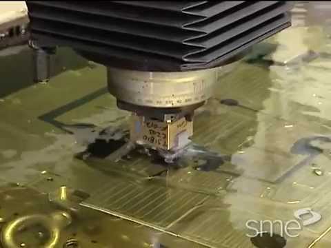
Manufacturers often integrate EDM manufacturing when the traditional machining manufacturing process has reached its limit. The EDM manufacturing process involves the integration of thermal energy to get rid of excess material from an object. Also, EDM manufacturing process delivers high accuracy and is suitable for any conductive material.
We will be examining how the EDM manufacturing process works, the types available, and the advantages.
What is EDM Manufacturing?
EDM simply stands for electrical discharge machining (EDM) involves the removal of a material from a workpiece by integrating thermal energy. EDM manufacturing is a non-traditional manufacturing method. It is similar to laser cutting. Also, EDM manufacturing requires no mechanical force during the removal process. Therefore, it is generally considered a non-traditional manufacturing method.
The EDM manufacturing process helps several industries in molding and tooling. Furthermore, EDM is popular as a result of its applicability particularly for hard materials or for complex shapes. Also, EDM manufacturing directs high-frequency electrical spark discharges to remove electrically conductive materials like carbide or hardened steel.
Electrical discharge machining EDM manufacturing uses electrode to disintegrate material from conductive materials. This non-traditional manufacturing approach helps engineers to achieve desired shapes with the integration of electrical discharges. Also, EDM manufacturing process is very precise and doesn’t require the use of tool on the workpiece.
A dielectric fluid helps to separate the electrodes used to remove material from a workpiece. After which a voltage passes through the dielectric fluid. Furthermore, EDM manufacturing works only for electrically conductive materials. One of these electrodes, which is the anode, changes shape to serve the exact purpose. The cathode is the other electrode. Two electrodes need to unite to achieve this.
Since EDM works well on hardened material, it is very easy to prevent possible deformation from heat treatment. Also, no cutting force is needed before the removal of the material.
Types of EDM Manufacturing
Hole drilling EDM
The hole drilling EDM manufacturing is commonly integrated to machine holes. This type of EDM can precisely machine very small and deep holes. These holes don’t need deburring. Also, hole drilling integrates similar basic rules as die-sinking EDM. The cut comprises a pulsing cylindrical electrode.
Hole drilling EDM plays a crucial role in the development of high-temperature turbine blades. This is because it enables the manufacturing of cooling channels in the turbine blades.
Wire EDM
This is also known as wire erosion. Wire EDM manufacturing is widely used to manufacturer extrusion dies. Also, it uses similar mechanism as die-sinking. However, in wire EDM, a fine electrically charged wire replaces the die. This wore act as the electrode. Wire EDM manufacturing method is similar to a cheese cutter that makes a two-dimensional cut in there dimensions.
The wire used in this type of EDM is always very thin. Also, the wire has a diameter that ranges from about 0.05mm to 0.35mm. Also, fresh wire spools throughout the machining process to prevent the use of burnt wire and deliver precise cutting. Wire EDM manufacturing produces precise cuts. However, integrating wire EDM only won’t produce square corners if you need to cut inside corners.
Die sinking EDM
Die sinking EDM is ideal for creating parts with complex cavities. Also, it is a method that provides a solution to internal corner issue when CNC machining. Furthermore, this die sinking method integrates copper electrodes or graphite and an electric spark put between the workpiece and the electrode.
In this method, the electrode is usually produced in a reverse shape of the cavity. Therefore, this creates the die. After which, the engineer induces a voltage between the electrically conductive workpiece and the die.
EDM manufacturing offers a lot of benefits in the technology world. These benefits include:
Precision
Although EDM offers limited efficiency in terms of producing large-volume orders, it is suitable for manufacturing prototypes and small parts as a result of its high precision levels. For instance, EDM is usually integrated within the automotive industry. Also, this industry requires high precision levels to manufacture intricate engine components.
Greater design freedom
One of the main benefits of EDM manufacturing is that it enables the cutting of depths and shapes. This would never be possible with traditional machining methods. Also, EDM manufacturing allows undercuts and square internal corners. Also, this machining process doesn’t produce a burr.
Requires no mechanical force
The need for no mechanical force in EDM manufacturing is one of the reasons it is highly preferred among manufacturers. EDM doesn’t put mechanical force in the workpiece and as such, you don’t need to worry about generating fragile outlines.
CNC milling usually leaves machining marks on a workpiece. These marks are usually removed by post-machining finishing. Also, EDM makes it possible to achieve uniformly smooth surfaces without any need for additional treatment. But, quick EDM manufacturing process can leave bead blasted-like texture behind.
Distortion-free machining
The tool in electrical discharge machining never comes in contact with the workpiece. Therefore, there is no distortion. As a result, every thin features machines without any risk of breaking. In addition, the absence of distortion means that you can achieve extremely tight tolerances.
Work on hardened material
One key feature of EDM is that it can work through any material in as much as it is conductive. Therefore, this indicates that EDM can machine tough materials like Tungsten carbide and Inconel.
Die-sinking EDM requires a reverse custom electrode. It is quite expensive to machine the electrode at low manufacturing volumes.
Low rate of material removal
The rate of material removal is very low in EDM manufacturing process. Since this process requires more power, the increase in production time will affect overall cost. Therefore, electrical discharge machining isn’t effective for large-scale project.
EDM requires a high amount of electricity to take place. Therefore, it isn’t an environmentally-conscious way of machining. Companies are beginning to adopt measures to minimize their carbon footprints. Therefore, they are opting for other machining methods that need low amount of electricity and are as well less harmful to the environment.
Can machine only conductive materials
EDM can only machine electrically conductive materials. Although, EDM manufacturing process can be stress-free, there is a thermal process that can affect the workpiece’s metallurgy.
Applications of EDM Manufacturing
EDM manufacturing is widely used in small-volume production. Therefore, it is applicable in several processes like small hole drilling, milling, and more. Also, this process is valuable for various industries such as aerospace and automotive. EDM is ideal for use in the following applications:
Die casting
EDM is ideal for use in die-making applications. Also, the production of dies needs extreme accuracy. These dies have deep ribs, internal corners, and some intricate features. Furthermore, dies comprise hard steel alloys which are harder to machine using traditional methods.
Injection molding
EDM determines how you can get the appropriate depth, shape, and dimension of a mold. In addition, EDM is an injection molding process commonly integrated by mold manufacturers. Injection molding demands different complex and delicate workpieces. Therefore, EDM is the best machining method to integrate.
Small hole drilling
EDM is a special way to make precise deep small holes in materials irrespective of their hardness. The hole drilling involves the use of a brass electrode tube.
Electrical discharge machining involves the use of different equipment like:
Power generator and control unit
Generator helps to integrate potential difference. Therefore, the voltage applied in this machining process is in pulse form. Furthermore, a control unit helps to regulate the operation during the process.
Servo system
The servo system helps to control the tool. Also, it maintains a gap between the workpiece and electrodes.
EDM can achieve tight tolerances of +/-0.012mm. Due to its high accuracy rate, EDM is widely used in medical and aerospace industries.
When can I use EDM?
EDM is ideal for use in drilling curved holes, cutting sharp internal corners, and cutting extrusions. Also, it is suitable for engraving on hard materials and cutting rotary forms.
What type of surface finish can EDM achieve?
Machining processes often maintain a balance between the surface finish quality and cutting speed. The initial cut is usually rougher and faster. However, the subsequent cuts are usually at a slower speed. To create an exceptional surface finish, you can make further tool passes at slower speeds. However, this increases the cost and time of machining.
Conclusion
EDM has been the solution for highly demanding machining applications. This machining process has helped engineers in applications where traditional approaches are impossible. Also, EDM helps to achieve exceptional results when combined with a traditional machining method like CNC machining. Also, the ability of EDM to machine hard materials make it ideal for machining materials such as Inconel.
The PCB industry is indeed a vast one. There are several printed circuit board companies spread across the world. Also, PCB production is a delicate process that needs to be handled by professionals. In those days, they were only a few PCB producers. However, with the increasing demand for electronic devices, there are now so many PCB companies available in our world today.
One of such is the APCT PCB manufacturing company. This company specializes in the design, production, and testing of printed circuit boards. Here, we will provide relevant information about the products and services provided by this industry-leading company.
The APCT PCB company is a leading manufacturer of high quality circuit boards. Also, this company has manufacturing sites in California, Santa Clara, southern California, and Wallingford. APCT PCB company has its headquarters located at California. Also, this company occupies 180,000 sq.ft space.
Founded in 1971, APCT PCB company has been delivering quality products and services since its establishment. Steve Robinson is the CEO of this company. He acquired APCT PCB in 2008 after working as a manager with a global PCB producer for years. . APCT stands for Advanced Printed Circuit Technology.
Over the years, APCT PCB company has produced a business model that differentiated it from its competitors in the PCB industry. Furthermore, APCT PCB company has been able to meet the needs and demands of customers over the years. Therefore, this company prides itself in delivering the best-quality PCBs to customers.
APCT believes that if it focuses on its business model, then it can beat industry standards in no time. Furthermore, APCT PCB takes pride in offering faster lead times while meeting the requirement of customers. With this, APCT will continue to deliver the best. The faster lead time provided by APCT PCB company means manufacturing will be completed within days rather than weeks.
APCT will deliver printed circuit boards when a client demands for Quick Turn Availability. Also, this PCB company has been able to earn the loyalty and trust from its customers and partners due to its reliable delivery of quick turn orders.
APCT features a global supply chain network. Therefore, it has got facilities in Southeast Asia, Japan, Sourthern China.
Every company has goals to achieve and there is always a mission to accomplish. For APCT PCB Company, there are three major cornerstones that drive it goals. These are commitment, passion, and trust. Also, these three cornerstones are what make this company stand out from its competitors.
APCT’s passion in what it does has helped it in delivering great customer satisfaction. Furthermore, this company’s commitment results from fostering innovation and service that supports its customers. APCT believes it can only earn the trust of its customers by its actions.
APCT keeps working diligently to provide technology solutions for standard PCBs and more advanced circuit boards. Also, APCT trusts its employees through a positive attitude and teamwork. Therefore, this helps to solidify its customer’s trust in its products and service.
Benefits of Choosing APCT PCB Manufacturing Company
APCT offers several benefits to its customers. This PCB company is widely known for its outstanding expertise in PCB fabrication.
Great reputation
PCB users love to patronize companies with great reputation. Over the years, APCT PCB company has built its reputation. Also, this company is known for delivering high quality and reliable circuit boards. These circuit boards have contributed to the development of some electronic devices.
High quality products
One of the numerous benefits of APCT PCB company is its high quality products. This company employs sophisticated technology and procedures during PCB fabrication. Also, it doesn’t compromise quality for price. Furthermore, APCT integrates several PCB inspection and testing methods to ensure quality control in the entire PCB production process.
APCT PCB company offers engineering supports to its customers. The core competency of APCT is its detailed engineering support that allows superior execution. Also, APCT provides offshore circuit board sourcing with domestic manufacturing infrastructure.
Faster lead times
APCT says yes to its customer’s lead time. Therefore, the fabrication process requires days and not weeks. Furthermore, APCT understands the need to beat competition in the PCB industry. Therefore, it delivers extremely quick lead times.
Versatility
This is one great benefit of APCT PCB company. APCT specializes in the design, production, and testing of various types of PCBs. Also, this company produces advanced circuit boards.
Industry-certified
APCT has the necessary certifications in PCB production. Also, this company ensures it adheres to some certain standards in the industry. For instance, APCT PCBs are RoHS compliant.
APCT circuit boards are widely used in a wide range of applications. You will find these circuit boards in several consumer electronics. Since APCT produces a wide range of printed circuit boards, these boards have several use cases.
Aerospace and defense
APCT PCB company fabricated advanced circuit boards that can withstand harsh environmental conditions. Furthermore, the circuit boards used in aerospace and defense electronic devices must meet some requirements. APCT PCBs meet these requirements.
Consumer electronics
APCT PCBs are ideal for use in consumer electronics like smartphones, TV, refrigerator, and more. Also, these boards offer a high level of reliability and as such, they contribute to the performance of these devices.
APCT PCBs are a perfect option for designing some automobile parts. These boards feature exceptional mechanical and thermal properties which make them applicable in the automotive industry.
Telecommunication
Some telecommunication devices feature APCT circuit boards. Also, these boards feature exceptional signal integrity and reduced EMI. Therefore, it functions well in telecommunication devices.
APCT PCBs are ideal for use in the production of military devices. Some military devices work under very harsh environmental conditions. APCT PCBs specially build its military circuit board to meet such requirements.
Conclusion
APCT offers one-stop solution to offshore PCB sourcing. This PCB company is relentless in its efforts to get rid of the obstacles of price, design, or delivery. From its standard through-hole to HDI and rigid-flex products, this company keeps delivering quality.
In addition to creating a well-known name in the installation as well as the entertainment sector, oem electronics takes a portion of contracts in the mechanical, software, firmware, and electronic design for brands that are well established, both outside and inside the entertainment industry.
Also, this broad skill set as well as the vast experience of the research and development team of OEM electronics, has allowed them to become a reliable shop for contract manufacturing, certification, and product design.
Whether you need one of their products in the PCBA format only to help in integrating it in your personal product, or you need a completely bespoke product, which is created completely from scratch, then the OEM electronic have different competitive solutions that help in fulfilling your needs.
What are the Services Rendered by the OEM Electronic Manufacturer?
Design
Teaming up with the project managers of OEM electronic, you will be able to establish the exact requirements. Furthermore, their R&D team could help in adding much value onto the process of product development by getting involved in all the stages in order to suit the customer’s project needs.
In addition, with testing, engineering and end to end design, the OEM electronic team helps in creating high-performance software, mechanical and electronic designs.
Furthermore, making use of their technical and creative problem-solving ability coupled with their vast experience in the industry, OEM electronic takes the concepts of their customers all through to its completion with proven and fully-industrialized engineering to make sure that they are set to launch the perfect product.
Manufacturing
OEM electronic has a top-notch factory that can handle high and consistent orders monthly to deliver complete and fully packaged products. This factory has the ability to support your project. Also, OEM electronic has the ability and capacity to offer full assembly services. They have a very dedicated team that makes sure of high detail and attention in all they do.
Furthermore, the operations of board assembly are for great flexibility. This helps in handling all the requirements of different customers. In addition, the OEM electronic makes use of different measuring equipment like integrating sphere and environmental chamber for light calibration and photometric measurements respectively.
Also, OEM electronic makes sure that they are updated with the efficient processes, highly skilled personnel, and advanced equipment, so as to offer reliable and long lasting printed circuit boards. In addition, the broad assembly capabilities of OEM electronic allow clients to have access to different turn-key and PCB solutions.
OEM Electronic product manufacturers usually pass through rigorous certification, testing, and design process before releasing them into the market. This same team of engineers is known to be responsible for different custom products. They make sure that everything leaving their factory has great attention to detail. These include the same amount of care, and a high level of professionalism.
Also, an oem manufacturer can design products having the ability of reaching, as well as surpassing the very strict criteria of the CQC, UL, and CE certification. These include offering the important documentation to go with the product whenever it is sent over for testing.
An original equipment manufacturer is a company whereby their goods are useful as components for products of a different company. This other company then sells the completed items to their customers or users. This second company is called VAR (value-added reseller). This is because they add value to the initial item by incorporating and integrating features as well as services.
The OEM electronic manufacturer and the VAR usually work hand in hand. The OEM electronic manufacturer produces sub-assembly parts to help in selling to the VARs. Though, some of the OEMs manufacture completed products for the VAR to sell or market them, most times, they don’t play a very direct role in the determination of the completed product.
Typically, there is no part that is integrated from a specific OEM. It is seen as playing a very important role in the completed product of the brand name of the VAR.
For instance people building their personal computers help in purchasing processors or graphic cards from Intel, Nvidia, as well as retailers which stock all these products. Also, if anyone wishes to do car repairs, they could purchase OEM electronic parts from a retailer. They can also reach the manufacturer directly from the retailer or manufacturer that sticks all these parts.
An example of the OEM is a relationship formed between the maker and the manufacturer of the auto parts. Parts such as brake cylinders or exhaust systems are usually manufactured by different OEMs.
The electronic distributors play a major role in the process of original equipment manufacturing. The large OEMs usually choose to work with the semiconductor suppliers. This helps in the early access and continuous supply to technology.
Furthermore, the small OEMs usually work with distributors to help them with product design, cost reduction, and a lot more. The distributors are usually a very important step to get your products to the market. Handling the marketing through the distributors is a strategy which many OEMs usually use in improving their partnerships and business.
Why are Distributors Very Important to the OEM Electronic Manufacturer?
Through the strategic relationships with the electronic distributors, OEM electronic can open or create additional doors for all their businesses. There are some benefits, which includes more time for testing, payment, and more.
When you partner with the distributors, it usually increases the possibility for it to branch out globally. With this, the OEM electronic manufacturer will ensure higher number of customers within a short time.
Conclusion
At Rayming PCB & Assembly, this relationship is very important. Our team boasts of over 20 years of professional experience working with the OEM electronic manufacturer. This will allow us to anticipate whatever your needs are as one of our partners. We will also help you find answers to your questions before you even ask them. With our years of expertise and experience, we have what it takes to meet your demands and needs.
Copper layers can be referred to as a printed circuit board (PCB) having copper present on it once etching is completed. This is usually pads and tracks or ground and power layers.
In this article we will be considering the functions of the copper layer in PCB. We’ll also discuss how you can generate the output files for your copper layers and more.
Two terms are very important for use in the PCB design.These include copper thieving and copper balancing. Though, they are usually used interchangeably, we will explain the important distinctions between them:
Copper balancing
Copper balancing involves the addition of non-conductive patterns and areas of copper into a printed circuit board. This alleviates the board’s possible bending when manufacturing is on. Furthermore, the PCB layer stackups, which aren’t configured symmetrically, can lead the warping of the board during fabrication.
Also, the uneven copper present in the structure of the board could also twist when the process of assembly as a result of too much heat utilized for soldering.In order to counter this, your design system of the PCB CAD will help in adding the area fills, and pours, to the board’s sparse areas to help copper balance your design.
Copper thieving
Copper thieving is adding non-conductive copper patterns to the printed circuit board. However, in cases like this, it is either to thieve or even out some electrical current utilized in the plating of the board. Also, on the board areas where there are lonely or isolated traces, the applied current onto the board to aid plating could be more concentrated or focused on the features.
The scenario could cause the trace to under-etch thereby delivering a kind of “mushroom” profile rather than the clean squared edges expected. The trace’s cross-section can depict serious undercutting, the trace present on the right side is squared off the way you want.
This is known as the cathode part of the electrolytic material. This material is deposited onto a continuous, thin, metal foil layer on the circuit board’s base. Furthermore, you can bond it easily onto an insulating layer, thereby accepting a protective layer, as well as corroded in order to form your circuit pattern.
Prepreg is culled from the word pre-impregnated. This is known as fiberglass that is impregnated with resin. This resin is pre-dried;however, it isn’t hardened. Therefore, when heated, it sticks, flows, and is fully immersed. Therefore, the prepregs are strengthened with fiberglass through an adhesive layer, which is just like the FR4 material. All the names of the prepregs are obtained from the fiberglass used.
What is the standard Thickness of the Copper Layer in PCB?
One of the mostly used units when measuring thickness of the copper layer in printed circuit boards (PCBs).However, majority of people don’t have an idea about the nature of its thickness. Sure it is not everyone that thinks it in mils and then converts into their preferred measuring unit using a unit conversion tool.
Furthermore, majority of PCBs are usually constructed using a copper thickness of 1 oz.During PCB manufacturing, when the customer doesn’t offer their specific specs, then the manufacturer usually assumes 1 oz whenever they are quoting as well as building the design. Furthermore, if the customer decides that their design needs additional current than the usual 1 oz could carry, then it is advisable to increase the thickness of the copper, as well as your traces’ widths.
Sure, the thicker your copper is, then the more the cost. However, there are some certain time when this becomes necessary. Also, the increase in cost doesn’t have to do with the costs of raw materials only but that the processing of thicker weights of copper consumes more time. Also, it is a bit trickier to perform or handle.
Processing the Thickness of the Copper Layer in PCB
Etching helps in manufacturing the board’s copper traces. This is the same whether it is for the internal layers or for the surface. Etching is one important step in PCB manufacturing. The layer fabrication starts with the laminate sheet, which is fully covered with copper. Etching has to do with getting rid of the excess copper that is present in traces, as well as other areas, like annular rings for the vias, component pads, making use of ammonia-based solution.
The sheets typically start with the copper thickness. The thickness could be etched down, increased, plated up, or decreased to the right specification. As a result of these sheets’ manufacturing process, the surface features a kind of roughness, which assists with the bonding to a specific dielectric material. Moreover, this could result in an adverse and negative effect on the signal integrity at a higher frequency.
Furthermore, at a frequency of more than 100MHz, this skin effect whereby current flows is usually close to the trace’s internal surface in contrast to the through the center of the conductor. This leads the trace’s effective resistance to rise and then oppose the flow of current.
How to Generate the Output Files for Your Copper Layers
Anytime you generate output data files, make use of “flashes” for the pads. This avoids pads that are “painted/drawn”.
Furthermore, for the larger copper planes or copper areas don’t fill them with using small draws or “painting”. Anywhere possible, make use of polygons or contours in constructing planes or areas. They are the standard features present in the Gerber X2 output and other data formats.
In addition, make sure that you add your board outline whenever you output the copper layer in PCB. This aids in the identification of any rotation, data alignment, as well as mirroring issues.
Achieving this is best making use of a specific small line, whereby the line’s center is the board outline.
Conclusion
We hope we have explained what the copper layer in PCB is all about. We are always here to assist you, if you have any questions.
Altium Designer is one of the most widely used printed circuit board (PCB) design software packages worldwide. This comprehensive article covers Altium Designer pricing and licensing options, free trial and full downloads, and a beginner tutorial on installing and using Altium Designer for the first time.
Introduction to Altium Designer
Altium Designer is a premium, professional-grade PCB and electronic product design software platform created by Altium LLC. Some key features include:
PCB design and layout with intelligent autorouting
Integrated 3D modeling for mechanical CAD collaboration
Version control, supply chain and product lifecycle management
Support for high-speed design, flex/rigid flex boards
Native support for MCAD file formats like STEP and IGES
Built-in library management and component database
Altium Designer aims to provide an end-to-end electronics design workflow in a unified environment. It competes with other premium PCB design software like Cadence Allegro and Mentor Graphics Xpedition.
Now let’s explore Altium Designer pricing options, free trials, full downloads and beginner tutorials.
Altium offers various pricing tiers and licensing options for Altium Designer to suit different customer needs:
Subscription License
A subscription license provides temporary access to Altium Designer for a recurring fee billed monthly or annually. It allows flexible scaling of seats as needs change.
Pricing:
1 month: $245/month
12 months: $180/month when billed annually
Volume discounts available for multiple seats
Perpetual License
A perpetual license provides permanent access to the version purchased. A maintenance plan is required to receive updates and support.
Pricing:
Base license: $10,000
Additional seats discounted ($7000 each)
Annual maintenance plan: roughly 20% of license cost
Academic pricing is also available for students and educational institutions. Consult Altium sales for current rates, discounts and collaborative licensing options.
Now let’s look at how to download, install and begin using Altium Designer.
Downloading and Installing Altium Designer
Several options exist for downloading Altium Designer:
Free Trial Download
A 15 day free trial of the latest Altium Designer version can be downloaded from:
The large download is around 5GB. An internet connection is required to validate the free trial license upon first use.
Subscription Installer
For the subscription version, Altium provides an installer download that streams the needed components as you use them. This allows a lighter initial install and more flexibility:
For situations with slow or no internet access, a full offline installer can be downloaded as well after signing in with an active subscription or permanent license.
The offline download is around 12GB in size. An internet connection is still periodically needed to validate the license.
Once Altium Designer is downloaded, run the installer (.exe file) and follow the step-by-step prompts to complete the installation process on your Windows PC.
Exploring Altium Designer for the First Time
The first time Altium Designer is launched, a modal dialog appears for activating a license. Sign in with your Altium account credentials or activate a free trial license.
Next, select a template. The “PCB Project” template is a good starting point as it includes both a PCB layout and corresponding schematic document.
Finally, a “Learn & Discover” introductory tour pops up. Take a few minutes to browse this interactive tutorial explaining Altium Designer’s interface and key capabilities.
When ready to dive in, the PCB editor will open by default to a simple sample layout. The dark interface theme and green accents match Altium’s branding.
Now let’s take a closer look at Altium Designer’s key parts and initial settings.
Altium Designer Interface Tour
Altium Designer’s main interface includes several key elements:
Menu Bar – Access to all features and commands. Recently used are pinned on right.
Toolbars – Frequently used actions like layout commands.
PCB Editor – Main design canvas for 2D/3D PCB layout.
Inspector Panels – Settings and properties for items selected in the editor.
Panels – Tabs like Projects or Libraries to browse project documents and design elements.
Notifications – Messages like errors and warnings appear subtly on lower right.
Status Bar – Information like cursor coordinates and design rule checks.
The interface adopts a dark color theme with green highlights by default. This can be changed in Preferences based on personal taste.
Next let’s adjust some preferences in Altium Designer.
Configuring Preferences in Altium
Many design settings and options can be configured in Altium Designer’s Preferences dialog. Go to Design > Preferences or press Ctrl+G to access them.
Key settings groups to check include:
System – General options like language and auto save.
Schematic – Options for schematic sheets, wires and other objects.
PCB Editor – Defaults for PCB layout, routing and display.
Data Management – Setup for connecting to version control or PLM systems.
For example, under System Preferences > User Interface, the overall theme and color scheme can be adjusted to your liking.
Poke around the different sections to get a feel for what settings are available in Preferences as you start to use Altium. Options can always be changed later as you gain experience.
Now let’s create a new schematic and PCB layout document.
To create a new blank schematic and PCB layout document in Altium Designer:
Click File > New > Project > PCB Project
Enter a project name like “MyFirstProject”
Click the Target Project Location drop down and browse to where the project files should be stored.
Ensure the “Add Schematic and PCB Files” box is checked.
Click Create Project
This will generate a new project with empty SCHDOC and PCBDOC documents ready for designing a basic two-layer circuit board.
Now we’re ready to start adding components and wiring up a schematic!
Placing Components in the Schematic
To begin putting together a circuit schematic in Altium:
Select the Schematic Library panel tab, expand the integrated library, and locate components to add.
Select a part like the common LM358 op amp.
Click to place it on the schematic sheet (it may auto-rotate).
Repeat to place additional parts like resistors, caps, wires and pins.
Use the Wiring Tool to connect component pins with wires.
Double click a part to edit its properties and parameter values.
Use the browser-like Schematic Libraries panel to place components, then wire them up!
Altium includes a large set of prebuilt schematic symbols and PCB footprints in its integrated libraries. Now let’s build a simple circuit.
Schematic Capture Example
Let’s create a basic schematic for a voltage divider circuit to see core symbol placement and wiring in action.
Place two resistors R1 and R2.
Place Ground and Voltage Source schematic symbols.
Use the Wiring tool to connect the components as shown:
Double click R1 and R2 to change resistance values, say to 10K and 1K.
Add net/wire labels like “Vout”.
With just a few clicks, a functional schematic comes together! Now we can transfer this to a PCB layout.
Generating a PCB from the Schematic
Once a schematic is completed in Altium Designer, generating the initial board outline and component placement on the PCB layout is straightforward:
Switch from the schematic editor to the PCB editor.
With the PCB document open, choose Design > Update PCB.
In the dialog, select the source schematic sheet and click OK.
The PCB will auto-populate with components from the schematic.
The synchronization goes both ways – from schematic to PCB, and from PCB changes back to the schematic. This bi-directional updating is a key benefit of Altium Designer.
Now let’s explore PCB layout editing and routing.
PCB Layout Editing in Altium
How to Panelize in AlTIum Designer
With the board outline and components imported, we can begin arranging parts and routing connections on the PCB.
On the PCB editor, parts can be moved either interactively or by changing X/Y coordinates in the Inspector panel.
Set the desired trace width and routing layers (Top, Bottom, etc).
Click on pads to insert linear trace segments. Right-angle corners are inserted automatically.
Complete tracing a connection by clicking the final pad.
Press Esc or click the Route button again when routing is complete.
Let’s route out the simple voltage divider circuit from the earlier schematic.
PCB Layout and Routing
Here is how the PCB editor looks after arranging parts and manually routing traces for the basic voltage divider:
With copper traces wired up, the electrical connections are complete. The PCB could be sent for fabrication at this point if desired!
Next we’ll use Altium’s auto router to more efficiently complete connections.
Auto Routing in Altium
Manually routing an intricate PCB layout can be extremely tedious. Altium Designer has an intelligent auto router to route connections rapidly:
Ensure all desired nets are named to guide the auto router.
Set routing layers allowed (Top, Bottom, etc).
Choose auto routing options like follow manual traces.
Run the auto router (Route > Interactive Routing > Auto Route).
The auto router will intelligently work to route remaining traces.
Tidy up traces or manually finish any incomplete connections.
With a mix of manual and auto routing, even large complex PCBs can be wired up very efficiently. The auto router helps finish the tedious parts.
For more advanced functionality like design rule checking, 3D modeling and manufacturing outputs, explore the many in-depth tutorials on Altium’s website and YouTube channel. The built-in help documentation also provides excellent feature explanations and examples.
Summary of Key Features
To recap, core Altium Designer capabilities as explored in this introductory tutorial include:
Unified, highly integrated schematic and PCB design environment.
Placement of components from schematic libraries.
Wiring up circuits and networks.
Synchronization between schematic and PCB.
Manual and intelligent auto routing of board traces.
Extensive component libraries and design reference materials.
There is much more to learn. But this basic tutorial illustrates how even a beginner can start creating schematics and circuit boards in Altium Designer quickly.
Altium Designer Guide and Resources
To leverage Altium Designer’s advanced features and streamlined workflows for electronics product development, consult the following resources:
Learning Guides – Altium offers free Designer Courses introducing key features and workflows:
With its comprehensive features, high integration and smart automation, Altium Designer helps streamline and accelerate the PCB design process. For engineers looking to master professional-grade electronics product development workflows, Altium Designer is a very worthwhile investment.
What are the main advantages of Altium Designer compared to low cost PCB design software?
Key advantages of Altium Designer versus entry-level tools like Eagle, KiCad or EasyEDA include:
Unified environment for schematic capture and PCB layout
Automated ECO changes synchronize schematics and boards
Advanced auto-routing for highly efficient trace wiring
Built-in 3D modeling and MCAD collaboration
Scripting and customization capabilities
Seamless version control and supply chain integrations
Access to component libraries and virtual components
The advanced capabilities justify the higher cost for professional users.
What skills are required to start using Altium Designer as a beginner?
To get started with Altium Designer as a new user, having general experience with:
Electrical engineering and schematic diagrams
Electronic components and PCB basics
Drafting and drawing board layouts
Using windows-based CAD software
will help tremendously. No prior experience with Altium or PCB design software is required. Altium provides documentation and videos tailored for first-time users of the platform.
What resources are available for learning more about Altium Designer?
The key resources available for learning Altium Designer in depth include:
Free training courses on Altium’s website
Documentation searchable by capabilities and features
Blogs and forum discussions
Official YouTube channel with tutorials
Altium’s monthly newsletter and design content
Live seminars and conference events
Between the software itself, built-in help, and wealth of training materials, there are excellent resources to master Altium Designer.