PCBs are an essential part of nearly all electric systems, and a single issue can lead to significant malfunctions. Although rare, most PCB problems arise from human error during the fabrication procedure.
Regrettably, the precision necessary for the proper functioning of circuit boards leaves more margin for human error, making it nearly impossible to eliminate them. Nonetheless, there are troubleshooting techniques available for circuit boards that can assist in resolving these issues.

Overview of Troubleshooting PCB
The accuracy of a PCB device relies on how precisely it performs its functions. However, human involvement in its manufacturing processes can introduce Trojan horses.
Most defects in PCB are typically caused by human error, such as incorrect soldering of components or the utilization of Improper voltages. Nonetheless, some flaws are not directly caused by human error, including component degradation.
A commonality between both types of Faults is that many of these Flaws are challenging to identify. Troubleshooting techniques can be beneficial in deciphering these issues and uncovering insights.
Troubleshooting PCB Deals With
The operation of the PCB electronics is centered around the electron flow, which is electricity moving from 1 level to another. Voltage & current regulation within a board is the basis for the functions of PCB electronics.
PCB electronics possess regulatory attributes thanks to components such as resistors, inductors, capacitors, or soldered wiring. Nevertheless, the electron flow pattern in the board can be disrupted by voltage spikes or powerful currents/ torrents, which can cause damage.
Intermittent failures are the term used to refer to the majority of defects caused by disruptions.
Factors To know Which Troubleshooting Technique Is to Repair PCB
The viability of a printed circuit board (PCB) troubleshooting technique depends on factors such as the no. of layers, size, assortment of elements, and more. Troubleshooting highly sophisticated PCBs may necessitate the use of specialized equipment.
In most cases, utilizing essential electrical appliances will suffice to troubleshoot PCBs effectively. It is because PCBs are generally straightforward to troubleshoot. As a result, you can often troubleshoot the average Printed circuit board without requiring sophisticated equipment.
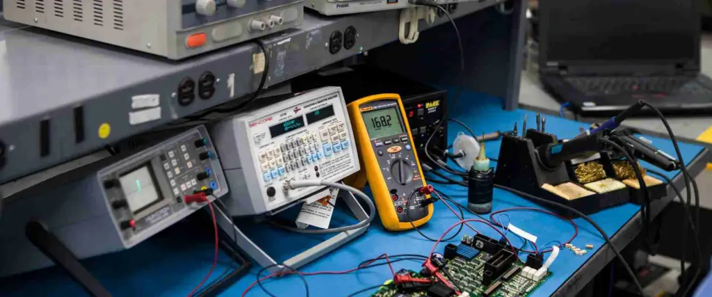
The multimeter is a highly versatile tool for diagnosing PCB issues. Nevertheless, in situations involving significant complexity, you may require advanced equipment like the analyzer and oscilloscope/LCR meter.
These tools enable the revelation of insights regarding the operational behaviors or mapping of a PCB.
Would you like to know more about troubleshooting and how its equipment uncovers Printed circuit board mapping & operations? The following chapter provides an in-depth analysis.
The Importance of Maping in Troubleshooting PCB
A standard PCB comprises a copper insulator network and traces that link groups of elements in a printed circuit board. The existence of the PCB’s schematic is one factor that can influence the ease of troubleshooting, as some PCBs are more straightforward to diagnose than others.
Having a comprehensive grasp of a PCB’s current flow, signals, and traces can facilitate the troubleshooting process. To diagnose issues accurately, it’s crucial to identify which capacitor corresponds to which resistor.
It’s crucial to comprehend the location of a voltage divider, choke, and filter on a PCB. However, if you’re unfamiliar with the Printed circuit board configuration, it’s advisable to commence troubleshooting by examining the connectors.
Connectors serve as the entry point for incorrect inputs from an outside environment, which can cause issues such as voltage spikes and over-current surges within the PCB. However, troubleshooting a Printed circuit board without an approach to its schematics necessitates a thorough understanding of its mapping. Otherwise, it may take a considerable amount of time to track the PCB’s configuration.
How To do Troubleshooting PCB?

Below are some essential initial steps to take when identifying PCB faults
· Visual Inspection
Performing a visual examination of the circuit board to spot burnt components, dry joints, and cracks is a simple and effective method of troubleshooting that doesn’t require power.
A high-quality optical magnifier is essential for visible inspections since there could be minor physical damages that might go unnoticed without one.
· Physical Inspection
If you don’t find anything important during the visible inspection, it’s time to verify the power supply. Make sure the IC gets the right amount of power.
Giving the IC the wrong amount of power can make the board overheat or overload. You can find where high current caused harm by touching the surface or components of the PBC.
When you touch different circuit components, you change the circuit’s impedance, which can also change how the system works. It can support you in finding the parts that require more capacitance.
To check if a component works correctly, you can use compressed canned air to cool a hotspot. But it’s essential to take some precautions while doing this.
When doing a physical inspection, it’s essential to touch the Printed circuit board with 1 hand at a time. It prevents electrical shocks from reaching your heart and causing fatal injury. It is always recommended to keep 1 hand in the pocket when working with the live circuit board.
Another essential precaution is blocking any feasible route for the current to reach the ground to prevent shocks. It includes avoiding standing barefoot and using a non-resistance grounding strap.
· Explicit Component Testing
At this point in troubleshooting, it’s time to apply measurement devices. Your first step is to measure the voltage of the power supply throughout the board.
Next, measure the currents at different board units to find areas with the wrong voltage. It is where having the circuit board diagram is helpful.
Common Troubleshooting PCB and Manufacturing Defects

Although there are various reasons why a PCB might be faulty, several of the most prevalent problems come from defects during manufacturing. Here are some issues that we frequently encounter during electronic servicing at AES:
· Exposed copper edges
Copper is an excellent conductor, but it is soft and can rust easily. To prevent this, copper used for Printed circuit boards must be covered with a protective coating. If copper edges are not coated properly, they can cause faults or shorts.
· Slivers of solder or copper
When making a PCB, small pieces of solder & copper masks can accidentally be left on a circuit board. So these slivers expose plating or cause Two separate copper parts to connect incorrectly. Both situations can cause a Printed circuit board fault.
· Plating gaps
If air bubbles or contaminants are present during a plating deposition procedure, it can result in cracks in the plating.
Moreover, a defective drill hit has the potential to destroy the PCBs.
· Incomplete solder masks
The purpose of solder masks is to protect copper connections or shield them from corrosive exposure. However, improper application of a solder mask among the 2 facing pads can result in issues with the Printed circuit board.
· Acid traps
In the PCB production’s etching phase, acid can get trapped in the acid trap process. This acid’s existence can make a circuit fundamentally faulty and lead to consequent problems
· Insufficient thermals
Thermals are utilized around printed circuit board pads to aid in heat dispersion. However, inconsistent application of thermals can result in connectivity issues with the PCB. Inadequate thermals may cause the PCB to overheat.
Ways for Troubleshooting PCB
· Inspect Visual Elements
In troubleshooting printed circuit boards, it is recommended to begin by carefully examining the printed circuit board. Conducting a visual inspection of the PCB can aid in identifying apparent issues like overheated components/ faulty connections.
The most straightforward way to identify an element error is by searching for minor brown marks on a printed circuit board. It can be completed without extensive electrical knowledge. Any dots indicate the overheated element that must be replaced. Additionally, bulging components and dull-looking links can serve as minor indicators of an error.
· Inspect Physical Components
After assessing the physical elements of the printed circuit boards, the next step is to perform the inspection with electricity running through the circuit. When the printed circuit board is linked to power, you can detect hot spots by feeling different areas on the printed circuit boards.
Typically, faulty connections and physical element issues cause specific spots on a printed circuit to become significantly hotter than the remaining ones. One can sense the temperature difference by touching the surface with a hand.
As a safety measure, it is essential to refrain from touching both hands on a live PCB simultaneously. Doing so can pose a severe risk of an electric shock passing through your heart, potentially leading to a fatal outcome. Therefore, to avoid injury, it is advisable to keep 1 hand off a printed circuit board during the procedure until it’s disconnected from a power source.
· Test Individual Components
The most efficient way to detect printed circuit board component failure is by using the multimeter to test each component individually. This method involves testing each capacitor, resistor, and other members separately to determine their functionality.
Each element should exhibit a reading at the stated value, indicating no issue with that component. However, if the reading exceeds the specified value, it means a problem.
· Test Integrated Circuits
Testing integrated PCBs is among the most challenging aspects of PCB troubleshooting, even for experts. It is primarily because integrated PCBs differ significantly, and there is a broad range of specialty integrated PCBs, making it nearly impossible for most people to test them accurately.
The most straightforward approach to diagnosing circuit boards is comparing them to a fully functional circuit board of the identical type. It is much easier to evaluate the functionality & behavior between two similar circuits than to diagnose an individual circuit.
· Inspect The Power Supply
To diagnose power supply issues, it is necessary to measure the power rails’ voltage using a multimeter. The output and input values should match the expected component values. If they do not, underlying issues may require further investigation.
If the voltage reading is 0V, it indicates the presence of a short board somewhere along a power rail, either in the regulator/capacitor. So, the element with the short circuit tends to heat rapidly, and one can feel the heat emanating from that specific unit.
· Compare a Defective Circuits
One of the simplest methods to diagnose PCB problems is using 2 same printed circuit boards. However, this method is only feasible if two identical PCBs are available. The following are the steps involved in this process:
Compare the 2 printed circuit boards visually to identify any noticeable problems like misplaced components or burn marks. The two boards should be nearly the same in every aspect, and any differences should be examined closely to identify specific problems.
· Use a multimeter to compare the behavior & functionality of the two PCBs, like the registered element(component) values, which should be nearly the same. Any differences observed are likely to indicate the physical component problem.
· Signal Probing
It is a complex troubleshooting process that requires expertise, but with a multimeter and waveform capture device, non-professionals can perform it. It involves measuring voltage and capturing waveforms at various points to identify where the problem is occurring. For more learning on advanced PCB testing techniques that involve signal probing, you can refer to our website.
· Dispose of Your Broken Printed Circuit Board
Disposing of printed circuit boards is not straightforward because certain parts of a printed circuit board can also be recycled while others cannot. Understanding the intricacies of circuit board recycling is a complex matter with multiple perspectives and approaches to consider.
Conclusion
It’s inevitable to encounter defective PCBs occasionally, which highlights the importance of being familiar with PCB troubleshooting methodologies. Although it may appear daunting at first glance, troubleshooting a printed circuit board is a relatively uncomplicated procedure, as demonstrated above.
While human mistakes cause most PCB errors during the manufacturing process, it is possible to acquire the skills to identify and rectify these errors. So in this way, you can also save both time & money.