Key Elements of an Ideal PWB Material from Rayming PCB

Introduction

Printed wiring boards (PWBs) or printed circuit boards (PCBs) serve as the foundation for modern electronics. The selection of appropriate PWB materials is crucial for ensuring optimal performance, reliability, and manufacturability. As electronic devices continue to evolve with increased complexity, higher power densities, and more demanding operating environments, the requirements for PWB materials have become increasingly stringent.

Rayming PCB, a leading manufacturer in the printed circuit board industry since 2005, has established comprehensive guidelines for evaluating and selecting optimal PWB materials. This comprehensive analysis explores the critical elements that define an ideal PWB material, encompassing electrical, thermal, mechanical, and chemical properties that directly impact circuit performance and reliability.

Electrical Properties: The Foundation of Signal Integrity

Dielectric Constant (Dk)

The dielectric constant is one of the most critical electrical properties for PWB materials. A stable and appropriate Dk value ensures predictable signal propagation characteristics and controlled impedance. The selection of dielectric constant depends heavily on the intended application frequency range.

For low-frequency applications below 1 GHz, typical Dk values range from 4.0-5.0 for general purpose applications, providing adequate performance for standard digital circuits. However, as frequencies increase into the medium range of 1-10 GHz, Dk values of 3.5-4.0 are preferred for high-speed digital applications. For the most demanding high-frequency applications exceeding 10 GHz, Dk values between 2.8-3.5 are essential for RF/Microwave applications.

The dielectric constant varies with frequency and generally decreases as frequency increases; some materials have less of a change in relative permittivity than others. This frequency stability is crucial for maintaining consistent signal integrity across the operating bandwidth.

Dissipation Factor (Df)

The dissipation factor, also known as loss tangent, directly impacts signal loss and is a critical parameter for high-frequency and high-speed applications. The classification of materials based on dissipation factor reveals distinct performance tiers:

  • Standard Grade Materials: Df range of 0.020-0.025 for basic performance level
  • Mid-tier Materials: Df range of 0.010-0.015 for intermediate performance
  • High-end Materials: Df range of 0.002-0.008 for advanced applications

Loss tangent determines how much of the electromagnetic energy from the signals in the conductors is absorbed in the board material. This factor is important for high frequencies. Selecting the appropriate dissipation factor is crucial for optimizing both performance and cost-effectiveness.

Thermal Properties: Managing Heat and Expansion

Glass Transition Temperature (Tg)

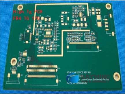
The glass transition temperature represents a fundamental thermal characteristic that defines the upper operational limit of PWB materials. Glass transition temperature, or Tg, is the temperature range in which a PCB substrate transitions from a glassy, rigid state to a softened, deformable state as polymer chains become more mobile.

Material selection based on glass transition temperature follows application-specific requirements:

  • 130-150ยฐC Range: Standard FR-4 materials suitable for consumer electronics and general-purpose applications
  • 155-180ยฐC Range: Enhanced materials for automotive and industrial applications requiring improved thermal stability
  • 200ยฐC and Above: High-performance materials for military, aerospace, and extreme environment applications

Polyimides with Tg of 250ยฐC or above are suitable for the highest temperature systems. Designers consider Tg as a rough indicator for total Z-axis expansion and hence, a proxy for reliability indication for plated through holes.

Thermal Conductivity

Most PCB substrates have a thermal conductivity in the range of 0.3 to 0.6 W/M-ยบC, which is quite low compared to copper, whose k is 386 W/M-ยบC. This limitation presents challenges for thermal management in high-power applications.

As critical devices could fail at rates doubling for every 10ยฐC increase of temperature, this pushes designers to use PWB materials with high thermal conductivity to remove heat directly from devices placed on the surface of the board. Advanced materials targeting thermal conductivity figures in the 1.0 to 3.0 W/m-K range, to achieve significant reduction in the board surface temperatures, especially near active devices.

For applications requiring superior thermal performance, ceramic materials are different in that their electrical conductivity is low enough for manufacturers to use them as PCB substrates, with aluminum nitride achieving thermal conductivity exceeding 170 W/mK.

Coefficient of Thermal Expansion (CTE)

Thermal expansion matching is crucial for maintaining reliability across temperature cycles. For the ideal PWB material, expansion in the Z-direction must match that of copper within the PTH to avoid damaging the plating inside the holes during thermal excursions in processes such as solder reflow.

The directional characteristics of CTE are particularly important:

  • X-Y Axis CTE: 14-17 ppm/ยฐC for PCB surface mounting applications
  • Z-Axis CTE: 50-70 ppm/ยฐC for through-hole reliability

Designers must match the expansion requirements of PWB materials to the expansion requirements of devices to be mounted on the surface, claddings, and the thermal planes buried in the interior.

Mechanical Properties: Structural Integrity and Durability

Flexural Strength

Mechanical strength requirements vary significantly based on application demands. The classification of materials by flexural strength provides guidance for appropriate selection:

  • Standard Materials: 350-400 MPa strength for general purpose applications
  • Reinforced Materials: 400-500 MPa strength for high-stress environments
  • High-performance Materials: greater than 500 MPa for Military/Aerospace applications

Substrate Material Selection

The design substrate material used in PWBs is crucial for its performance and durability. Commonly used materials include phenolic paper, epoxy glass, and polyimide. Each material offers distinct advantages:

  • Phenolic Paper: Cost-effective option providing moderate electrical insulation and mechanical strength
  • Epoxy Glass: Enhanced electrical insulation and mechanical stability for demanding applications
  • Polyimide: High-performance material with excellent thermal stability and chemical resistance for aerospace and military applications

Chemical and Environmental Resistance

Moisture Absorption

Moisture absorption affects the thermal and electrical properties of the substrate, as well as the ability of the material to resist conductive anode filament (CAF) formation when a PCB circuit is powered. Different materials exhibit varying susceptibility to moisture:

  • FR-4 Epoxy: Absorption of only 0.15%
  • PTFE (Teflon): Very low absorption of 0.01%
  • Polyimide: Higher water absorption (0.4%)

Absorbed moisture can also vaporize on heating, as during soldering, and cause cracking and delamination, the same effect responsible for “popcorning” damage on wet packaging of electronic parts.

Chemical Resistance

Material resistance to processing chemicals and environmental exposure is essential for long-term reliability. Methylene chloride resistance is a measure of a material’s chemical resistance; specifically, the ability of a PCB material to resist methylene chloride absorption. Most materials achieve resistance values between 0.01% to 0.20%.

Manufacturing and Processing Considerations

Lead-Free Compatibility

PWB materials compatible with lead-free processes need to withstand higher soldering and reflow temperatures associated with lead-free solder systemsโ€”typically 30 to 50ยฐC higher than traditional lead-tin systems. The requirements for lead-free compatible materials include:

  • Glass Transition Temperature: Greater than 155ยฐC
  • Decomposition Temperature: Greater than 330ยฐC for 5% decomposition
  • Overall CTE: Less than 3.5%

Lamination Parameters

Lamination requirements include temperature ranges of 175-185ยฐC, pressure of 250-400 PSI, and time periods of 45-90 minutes, with specific parameters dependent on material glass transition temperature, thickness, and layer count.

Cost Considerations and Material Selection

The economic impact of material selection extends beyond initial material costs. Material selection significantly impacts costs through both direct material expenses and processing requirements. High-performance materials can cost 3-6 times more than standard FR-4 and may require specialized processing parameters.

Material cost comparison reveals distinct tiers:

  • FR-4: Base cost reference (1x)
  • Modified FR-4: 1.5-2x base cost for enhanced performance
  • High-speed Materials: 3-4x base cost for superior characteristics
  • RF/Microwave Materials: 4-6x base cost for premium performance

Advanced Material Technologies and Future Trends

High-Frequency Specialized Materials

For demanding RF and microwave applications, specialized materials offer superior performance characteristics. Property tolerances include Dk tolerance of ยฑ0.05 and other tightly controlled parameters essential for maintaining signal integrity at extreme frequencies.

Emerging Technologies

Current trends include the development of bio-based sustainable materials, integration of nanomaterials for enhanced properties, and smart materials with built-in monitoring capabilities. These innovations aim to address environmental concerns while improving performance.

Quality Assurance and Testing Standards

Comprehensive testing protocols ensure material compliance with performance specifications:

  • Electrical Testing: IPC-TM-650 standards for dielectric constant and dissipation factor measurement
  • Thermal Testing: ASTM D3850 standards for glass transition temperature and coefficient of thermal expansion
  • Mechanical Testing: ASTM D790 standards for flexural strength evaluation

Conclusion

The selection of ideal PWB materials requires careful consideration of multiple interdependent factors including electrical properties, thermal characteristics, mechanical strength, chemical resistance, and manufacturing compatibility. The most critical factor depends on the application, but generally, the combination of electrical properties (Dk and Df) and thermal performance (Tg and CTE) are paramount. These properties directly impact signal integrity and reliability.

Rayming PCB’s comprehensive approach to material evaluation ensures that designers can make informed decisions based on specific application requirements while optimizing both performance and cost-effectiveness. As electronic systems continue to advance in complexity and operating demands, the importance of proper PWB material selection becomes increasingly critical for achieving reliable, high-performance electronic products.

The evolution toward more sustainable and advanced materials, including bio-based alternatives and nanomaterial-enhanced substrates, represents the future direction of PWB material technology, promising improved performance while addressing environmental considerations that are becoming increasingly important in modern electronics manufacturing.

Learn why Rogers RO3000 Materials are Chosen for High-End RF Applications | RAYMING PCB

In the world of high-frequency electronics and radio frequency (RF) applications, the choice of materials used in the design and manufacturing processes is crucial. One material that has gained widespread recognition for its exceptional performance in high-end RF applications is the Rogers RO3000 series.

Rogers Corporation, a leading manufacturer of advanced materials for various industries, has developed the RO3000 series specifically to meet the demanding requirements of high-frequency circuits and systems. This article delves into the unique properties and advantages of Rogers RO3000 materials, exploring the reasons why they are a popular choice among engineers and designers working on cutting-edge RF applications.

YouTube video

What are Rogers RO3000 Materials?

The Rogers RO3000 series comprises a range of high-frequency circuit materials designed for applications operating from high MHz to millimeter-wave frequencies. These materials are based on a proprietary thermoset ceramic hydrocarbon polymer resin, reinforced with ceramic filler materials.

The RO3000 series includes several variants, each optimized for specific performance characteristics and frequency ranges. Some of the most commonly used materials in the series are:

RO3003โ„ข and RO3006โ„ข

  • Designed for applications up to 40 GHz
  • Excellent electrical and mechanical stability over a wide temperature range
  • Low loss and consistent electrical properties

RO3010โ„ข and RO3035โ„ข

  • Suitable for applications up to 77 GHz
  • Ultra-low loss and low dielectric constant
  • Excellent phase and amplitude stability

RO3203โ„ข and RO3206โ„ข

RO3210โ„ข

  • Designed for applications up to 110 GHz
  • Extremely low loss and low dielectric constant
  • Ideal for millimeter-wave applications
RayMing Rogers Ro3003 PCB Board 0.8 Thickness

RayMing Rogers Ro3003 PCB Board 0.8 Thickness

Original price was: $540.00.Current price is: $520.00.

Rogers Ro3003 PCB Board 0.8 Thickness 2 Layer PCB Dielectric Constant: 3.0 Size: 220 x 80mm Rogers Ro3003 Laminates Datasheet RO3000 Laminate Data Sheet RO3003 – RO3006 – RO3010 – RO3035 What is Rogers Ro3003 ? The Rogers Ro3003 is a high-frequency laminate material widely used for printed circuit boards (PCBs) in various applications, such…

Category:
Tags: ,

Why Choose Rogers RO3000 Materials?

The Rogers RO3000 materials are widely chosen for high-end RF applications due to their exceptional electrical and mechanical properties, which are essential for achieving optimal performance in these demanding applications.

Electrical Properties

Low Dielectric Loss

One of the most critical factors in high-frequency applications is minimizing signal loss. Rogers RO3000 materials exhibit exceptionally low dielectric loss, which translates into minimal signal attenuation and increased efficiency. This characteristic is particularly important in applications such as power amplifiers, filters, and antennas, where signal integrity is paramount.

Low Dielectric Constant

The RO3000 series materials have a low dielectric constant, which is desirable for high-frequency applications. A lower dielectric constant results in higher signal propagation speeds and reduced signal distortion, enabling better performance and higher data rates.

Consistent Electrical Properties

The electrical properties of Rogers RO3000 materials, such as dielectric constant and dissipation factor, remain consistent across a wide range of frequencies and temperatures. This consistency ensures reliable and predictable performance, even in challenging operating conditions.

Mechanical Properties

Low Coefficient of Thermal Expansion (CTE)

The RO3000 materials have a low coefficient of thermal expansion, which means they exhibit minimal dimensional changes over a wide temperature range. This property is crucial for maintaining the integrity of high-frequency circuits, preventing issues such as delamination or cracking caused by thermal stress.

High Thermal Conductivity

Many materials in the RO3000 series feature high thermal conductivity, which aids in efficient heat dissipation. This characteristic is particularly important in high-power applications, where thermal management is critical for reliable operation and extended component life.

Excellent Dimensional Stability

Rogers RO3000 materials maintain their dimensional stability over a wide range of temperatures and environmental conditions. This property ensures that the electrical performance remains consistent, even in demanding environments, reducing the risk of signal degradation or circuit failure.

Applications of Rogers RO3000 Materials

Due to their exceptional electrical and mechanical properties, Rogers RO3000 materials are widely used in a variety of high-end RF applications across various industries, including:

Telecommunications

  • Base station antennas
  • Wireless infrastructure
  • Satellite communications
  • Radar systems

Aerospace and Defense

  • Avionics systems
  • Missile guidance systems
  • Electronic warfare systems
  • Unmanned aerial vehicles (UAVs)

Automotive and Transportation

  • Automotive radar systems
  • Advanced driver assistance systems (ADAS)
  • Vehicle-to-vehicle (V2V) and vehicle-to-infrastructure (V2I) communication systems

Medical and Scientific

  • Magnetic resonance imaging (MRI) systems
  • Particle accelerators
  • Biomedical imaging equipment

Test and Measurement

  • High-frequency test equipment
  • Vector network analyzers
  • Signal generators
  • Spectrum analyzers

Advantages of Using Rogers RO3000 Materials

Choosing Rogers RO3000 materials for high-end RF applications offers several advantages, including:

  1. High Performance: The exceptional electrical and mechanical properties of RO3000 materials ensure superior performance in high-frequency applications, enabling efficient signal transmission, low signal loss, and reliable operation.
  2. Consistent Quality: Rogers Corporation maintains stringent quality control measures, ensuring consistent material properties and performance across different batches and production runs.
  3. Proven Track Record: Rogers RO3000 materials have been extensively used in various industries and applications, demonstrating their reliability and performance in real-world scenarios.
  4. Wide Range of Options: The RO3000 series offers a variety of materials optimized for different frequency ranges and performance requirements, allowing designers to choose the most suitable option for their specific application.
  5. Technical Support: Rogers Corporation provides comprehensive technical support and resources, including design guides, simulation tools, and application notes, to assist engineers and designers in optimizing their designs using RO3000 materials.

Frequently Asked Questions (FAQ)

  1. Q: What is the primary advantage of using Rogers RO3000 materials in high-frequency applications? A: The primary advantage of using Rogers RO3000 materials in high-frequency applications is their exceptionally low dielectric loss, which minimizes signal attenuation and ensures efficient signal transmission.
  2. Q: Can Rogers RO3000 materials be used in high-power applications? A: Yes, many materials in the RO3000 series, such as RO3003 and RO3006, have high thermal conductivity, making them suitable for high-power applications that require efficient heat dissipation.
  3. Q: How do Rogers RO3000 materials compare to other high-frequency circuit materials? A: Rogers RO3000 materials offer superior electrical performance, with lower dielectric loss and more consistent properties compared to many other high-frequency circuit materials. Additionally, they exhibit excellent dimensional stability and low coefficient of thermal expansion, ensuring reliable performance in demanding environments.
  4. Q: Are Rogers RO3000 materials suitable for millimeter-wave applications? A: Absolutely. The RO3000 series includes materials like RO3210, which are specifically designed for applications up to 110 GHz, making them ideal for millimeter-wave applications.
  5. Q: What industries commonly use Rogers RO3000 materials? A: Rogers RO3000 materials are widely used in various industries that require high-frequency and high-performance applications, including telecommunications, aerospace and defense, automotive and transportation, medical and scientific, and test and measurement equipment.

Conclusion

Rogers RO3000 materials have become the go-to choice for many engineers and designers working on high-end RF applications. Their exceptional electrical and mechanical properties, combined with consistent performance and reliability, make them an ideal solution for a wide range of applications operating at high frequencies and demanding environments.

From telecommunications and aerospace to automotive and medical industries, the RO3000 series materials have proven their worth in supporting the development of cutting-edge technologies that rely on efficient and reliable high-frequency signal transmission.

By choosing Rogers RO3000 materials, designers can be confident in achieving optimal performance, durability, and longevity for their high-end RF applications, solidifying Rogers Corporation’s position as a leading provider of advanced materials for the electronics industry.

Rogers PCB Vs. Nelco laminates Vs. Taconic material Vs. Arlon: From Design,Manufacturing to Cost FOR Microwave Electronics

Rogers RO4500 PCB

In the realm of microwave electronics, the choice of materials for printed circuit boards (PCBs) is crucial for achieving optimal performance, reliability, and cost-effectiveness. Among the leading manufacturers of high-frequency laminates are Rogers Corporation, Nelco, Taconic, and Arlon. These companies offer a wide range of materials tailored for various microwave applications, each with its unique properties and characteristics. In this article, we will delve into the design, manufacturing, and cost considerations of these materials, providing a comprehensive comparison to assist engineers and designers in making informed decisions.

Introduction to High-Frequency Laminates

High-frequency laminates, also known as microwave laminates or RF substrates, are specialized materials used in the fabrication of PCBs for applications operating at high frequencies, such as microwave and radio frequency (RF) circuits. These materials are engineered to exhibit exceptional electrical properties, including low dielectric constant, low dissipation factor, and consistent performance over a wide frequency range.

Microwave electronics encompass a diverse range of applications, including telecommunications, radar systems, satellite communications, and aerospace electronics. The performance and reliability of these systems heavily rely on the quality of the PCB materials used, making the selection of the appropriate laminate a critical decision.

Rogers PCB Materials

Rogers AD255C PCB

Rogers Corporation is a renowned manufacturer of high-performance materials for various applications, including microwave electronics. Their PCB materials are widely used in the industry due to their excellent electrical properties and thermal stability.

1. Rogers PCB Material Overview

Rogers offers a comprehensive portfolio of PCB materials designed for microwave and RF applications, including:

  • RO3000ยฎ Series: Ceramic-filled hydrocarbon composites with exceptional electrical properties, suitable for high-frequency and high-speed digital circuits.
  • RT/duroidยฎ Series: Glass microfiber reinforced PTFE (polytetrafluoroethylene) laminates known for their low dielectric constant and low dissipation factor.
  • RO4000ยฎ Series: Hydrocarbon-based laminates with excellent dimensional stability and electrical properties for high-frequency and high-speed digital applications.
  • TC Series: Thermoset ceramic-filled composites designed for high-temperature and high-reliability applications.

2. Design and Manufacturing Considerations

Rogers PCB materials are engineered to meet the stringent requirements of microwave electronics. The design and manufacturing processes involve careful consideration of various factors, including:

  • Dielectric Constant: The dielectric constant of the material is a critical parameter that affects the propagation of electromagnetic waves. Rogers materials are designed to have a low and stable dielectric constant over a wide frequency range, enabling efficient signal transmission.
  • Dissipation Factor: The dissipation factor, also known as the loss tangent, represents the energy lost as heat in the material. Rogers materials exhibit exceptionally low dissipation factors, minimizing signal attenuation and ensuring efficient power transfer.
  • Thermal Conductivity and Coefficient of Thermal Expansion (CTE): Thermal management is crucial in microwave electronics. Rogers materials are designed with high thermal conductivity and low CTE to dissipate heat effectively and maintain dimensional stability under temperature variations.
  • Mechanical Strength and Dimensional Stability: The mechanical properties of Rogers materials, such as tensile strength and dimensional stability, ensure reliable performance and consistent electrical characteristics in demanding environments.

3. Cost Considerations

While Rogers PCB materials offer superior performance, they typically come at a higher cost compared to other laminate options. The advanced materials and specialized manufacturing processes contribute to the increased cost. However, for critical applications where high performance and reliability are paramount, the investment in Rogers materials can provide long-term benefits and cost savings through improved system performance and reduced maintenance requirements.

Nelco Laminates

Nelco N4000-13 High-Speed pcb

Nelco is a leading manufacturer of high-frequency laminates, offering a range of materials designed for microwave and RF applications.

1. Nelco Laminate Overview

Nelco’s product portfolio includes:

  • N4000 Series: Glass-reinforced hydrocarbon/ceramic composite laminates with low dielectric constant and dissipation factor.
  • N6000 Series: Woven glass-reinforced PTFE laminates with excellent electrical properties and thermal stability.
  • N8000 Series: Thermoplastic composites with low dielectric constant and dissipation factor, suitable for high-frequency applications.

2. Design and Manufacturing Considerations

Nelco laminates are engineered to meet the demanding requirements of microwave electronics, with a focus on electrical performance, thermal management, and mechanical properties. Key considerations include:

  • Dielectric Constant and Dissipation Factor: Nelco laminates are designed to maintain stable electrical properties over a wide frequency range, ensuring efficient signal transmission and low signal loss.
  • Thermal Conductivity and CTE: Nelco materials are engineered with high thermal conductivity and low CTE to dissipate heat effectively and maintain dimensional stability under temperature variations.
  • Mechanical Strength and Dimensional Stability: The mechanical properties of Nelco laminates, such as tensile strength and dimensional stability, are optimized to provide reliable performance in demanding environments.

3. Cost Considerations

Nelco laminates are generally more cost-effective than Rogers materials, while still offering excellent performance for many microwave and RF applications. The choice between Nelco and Rogers materials often involves weighing the trade-off between cost and performance based on specific application requirements.

Taconic Materials

Taconic is another leading manufacturer of high-frequency laminates, offering a wide range of materials tailored for various microwave and RF applications.

1. Taconic Material Overview

Taconic’s product portfolio includes:

  • TacCladยฎ Series: PTFE-based laminates with low dielectric constant and dissipation factor, suitable for high-frequency and high-speed digital applications.
  • TacQuikยฎ Series: Thermoset laminates with excellent electrical properties and thermal stability, designed for high-reliability applications.
  • TacSilยฎ Series: Silicone-based laminates with low dielectric constant and dissipation factor, suitable for high-frequency and high-temperature applications.

2. Design and Manufacturing Considerations

Taconic materials are engineered to meet the stringent requirements of microwave electronics, with a focus on electrical performance, thermal management, and mechanical properties. Key considerations include:

  • Dielectric Constant and Dissipation Factor: Taconic materials are designed to maintain stable electrical properties over a wide frequency range, ensuring efficient signal transmission and low signal loss.
  • Thermal Conductivity and CTE: Taconic materials are engineered with high thermal conductivity and low CTE to dissipate heat effectively and maintain dimensional stability under temperature variations.
  • Mechanical Strength and Dimensional Stability: The mechanical properties of Taconic materials, such as tensile strength and dimensional stability, are optimized to provide reliable performance in demanding environments.

3. Cost Considerations

Taconic materials are generally comparable in cost to Nelco laminates, offering a balance between performance and cost-effectiveness for many microwave and RF applications. The choice between Taconic and other manufacturers often depends on specific application requirements and performance trade-offs.

Arlon Materials

Arlon 55NT PCB

Arlon is a well-established manufacturer of high-frequency laminates, offering a range of materials suitable for microwave and RF applications.

1. Arlon Material Overview

Arlon’s product portfolio includes:

  • 25N Series: Woven glass-reinforced PTFE laminates with low dielectric constant and dissipation factor, suitable for high-frequency and high-speed digital applications.
  • 35N Series: Woven glass-reinforced hydrocarbon/ceramic composite laminates with excellent electrical properties and thermal stability.
  • AD Series: Thermoset laminates with low dielectric constant and dissipation factor, designed for high-reliability applications.

2. Design and Manufacturing Considerations

Arlon materials are engineered to meet the demanding requirements of microwave electronics, with a focus on electrical performance, thermal management, and mechanical properties. Key considerations include:

  • Dielectric Constant and Dissipation Factor: Arlon materials are designed to maintain stable electrical properties over a wide frequency range, ensuring efficient signal transmission and low signal loss.
  • Thermal Conductivity and CTE: Arlon materials are engineered with high thermal conductivity and low CTE to dissipate heat effectively and maintain dimensional stability under temperature variations.
  • Mechanical Strength and Dimensional Stability: The mechanical properties of Arlon materials, such as tensile strength and dimensional stability, are optimized to provide reliable performance in demanding environments.

3. Cost Considerations

Arlon materials are generally comparable in cost to other leading manufacturers in the microwave and RF laminate market. The choice between Arlon and other materials often depends on specific application requirements, performance trade-offs, and supplier relationships.

Comparison of Materials

To assist in the selection process, the following table provides a comparison of the key properties and characteristics of the materials discussed:

MaterialDielectric ConstantDissipation FactorThermal ConductivityCTEMechanical StrengthCost
Rogers PCB MaterialsVery LowVery LowHighLowExcellentHigh
Nelco LaminatesLowLowHighLowExcellentModerate
Taconic MaterialsLowLowHighLowExcellentModerate
Arlon MaterialsLowLowHighLowExcellentModerate

It’s important to note that the specific values of these properties may vary among different product lines within each manufacturer, and the selection should be based on the detailed material specifications and application requirements.

FAQs (Frequently Asked Questions)

  1. What are the key factors to consider when selecting a high-frequency laminate for microwave electronics? The key factors to consider include dielectric constant, dissipation factor, thermal conductivity, coefficient of thermal expansion (CTE), mechanical strength, dimensional stability, and cost. These factors directly impact the electrical performance, thermal management, and reliability of the microwave circuit.
  2. How do Rogers PCB materials compare to other laminates in terms of electrical performance? Rogers PCB materials, such as the RO3000ยฎ and RT/duroidยฎ series, are known for their exceptional electrical performance, with very low dielectric constant and dissipation factor. These materials offer superior signal transmission and minimal signal loss compared to many other high-frequency laminates.
  3. Are there any environmental or regulatory considerations when choosing a high-frequency laminate? Yes, environmental and regulatory considerations are important factors in material selection. Some manufacturers offer halogen-free and RoHS-compliant materials to meet environmental regulations. Additionally, certain applications may require materials with specific certifications or compliance standards.
  4. Can high-frequency laminates be used for flexible circuit applications? Yes, some manufacturers offer flexible high-frequency laminates that can be used for applications requiring flexible or conformal circuits. These materials combine the electrical properties of microwave laminates with flexibility and conformability.
  5. How does the cost of high-frequency laminates vary among different manufacturers? The cost of high-frequency laminates can vary significantly among different manufacturers. Generally, Rogers PCB materials are considered higher-cost options due to their advanced materials and specialized manufacturing processes. Nelco, Taconic, and Arlon laminates are typically more cost-effective while still offering excellent performance for many microwave and RF applications.

When selecting a high-frequency laminate for microwave electronics, it is crucial to consider the specific application requirements, performance needs, and cost constraints. Consulting with material experts and suppliers can help ensure the optimal choice for your design and manufacturing process.

Radar PCB Design Guide: Key Considerations for High-Frequency & RF Applications

In the rapidly evolving world of electronics, radar technology continues to play a crucial role in various applications, from automotive safety systems to weather forecasting and military defense. At the heart of these advanced radar systems lies a critical component: the Radar Printed Circuit Board (PCB). Designing PCBs for radar applications requires a deep understanding of high-frequency and Radio Frequency (RF) considerations. This comprehensive guide will explore the key aspects of Radar PCB design, providing valuable insights for engineers and designers working on cutting-edge radar technology.

Understanding Radar PCB Basics

What is a Radar PCB?

A Radar PCB is a specialized printed circuit board designed to handle the unique requirements of radar systems. These PCBs are engineered to work with high-frequency signals, typically in the range of 1 GHz to 100 GHz or even higher. Radar PCBs must maintain signal integrity, minimize noise, and ensure precise timing to accurately detect and process reflected electromagnetic waves.

Key Components of Radar PCBs

  1. Transmitter circuitry
  2. Receiver circuitry
  3. Signal processing units
  4. Power management systems
  5. Antenna interfaces

Importance of Proper Radar PCB Design

Effective Radar PCB design is crucial for:

  1. Maximizing radar system performance
  2. Ensuring reliability in challenging environments
  3. Minimizing electromagnetic interference (EMI)
  4. Optimizing power efficiency
  5. Reducing overall system cost

High-Frequency Considerations in Radar PCB Design

Understanding High-Frequency Behavior

When designing Radar PCBs, it’s essential to consider how high-frequency signals behave differently from low-frequency signals:

  1. Increased skin effect
  2. Greater susceptibility to electromagnetic interference
  3. Higher risk of signal reflection and crosstalk
  4. Importance of impedance control

Selecting Appropriate PCB Materials

Choosing the right PCB material is crucial for high-frequency radar applications:

  1. Low-loss materials: FR-4, Rogers 4000 series, Taconic RF series
  2. Consider dielectric constant (Dk) and dissipation factor (Df)
  3. Thermal stability and coefficient of thermal expansion (CTE)
  4. Cost vs. performance trade-offs

Transmission Line Design

Proper transmission line design is critical for maintaining signal integrity:

  1. Microstrip vs. stripline configurations
  2. Controlled impedance routing
  3. Minimizing discontinuities and transitions
  4. Use of ground planes and power planes

RF Considerations in Radar PCB Design

RF Signal Integrity

Maintaining RF signal integrity is paramount in radar PCB design:

  1. Minimizing signal loss and distortion
  2. Proper termination of RF traces
  3. Avoiding unwanted resonances
  4. Managing return loss and insertion loss

RF Shielding Techniques

Effective RF shielding is essential to prevent interference:

  1. Use of EMI/RFI shielding materials
  2. Proper grounding and shielding of sensitive components
  3. Implementing guard traces and ground vias
  4. Designing effective shield walls and compartments

Antenna Integration

Integrating antennas with Radar PCBs requires careful consideration:

  1. Impedance matching between antenna and PCB
  2. Minimizing feed line losses
  3. Proper placement of antenna elements
  4. Considering array configurations for phased array radars

Layer Stack-Up and Routing Strategies

Optimal Layer Stack-Up Design

Proper layer stack-up is crucial for high-frequency radar PCBs:

  1. Determining the appropriate number of layers
  2. Alternating signal and ground layers
  3. Maintaining symmetry in the stack-up
  4. Considering buried and blind vias

Effective Routing Techniques

Optimizing trace routing is essential for radar PCB performance:

  1. Implementing differential pair routing
  2. Avoiding 90-degree angles in traces
  3. Utilizing serpentine routing for length matching
  4. Managing return paths for high-frequency signals

Ground Plane and Power Distribution

Proper ground plane and power distribution design is critical:

  1. Implementing solid ground planes
  2. Minimizing splits in ground and power planes
  3. Using stitching capacitors and vias
  4. Designing effective power distribution networks (PDN)

Read more about:

Component Selection and Placement

Choosing RF-Compatible Components

Selecting the right components is crucial for radar PCB performance:

  1. Low-noise amplifiers (LNAs)
  2. RF mixers and oscillators
  3. High-speed ADCs and DACs
  4. RF-specific passive components

Optimal Component Placement

Strategic component placement can significantly impact radar PCB performance:

  1. Minimizing trace lengths for critical signals
  2. Grouping related components together
  3. Considering thermal management in component placement
  4. Implementing proper decoupling and bypass capacitor placement

Thermal Management Considerations

Effective thermal management is essential for reliable radar PCB operation:

  1. Identifying and managing hot spots
  2. Implementing thermal vias and copper pours
  3. Considering the use of heat sinks and thermal interfaces
  4. Designing for proper airflow and cooling

Signal Integrity and Noise Reduction

Managing Signal Integrity

Maintaining signal integrity is crucial for accurate radar operation:

  1. Controlling impedance throughout the board
  2. Minimizing crosstalk between adjacent traces
  3. Managing signal reflections and ringing
  4. Implementing proper termination techniques

Noise Reduction Strategies

Minimizing noise is essential for maximizing radar sensitivity:

  1. Proper isolation of analog and digital sections
  2. Implementing power supply filtering and decoupling
  3. Using guard rings around sensitive components
  4. Considering the use of spread spectrum techniques

EMI/EMC Considerations

Ensuring electromagnetic compatibility is critical for radar systems:

  1. Designing for regulatory compliance (e.g., FCC, CE)
  2. Implementing proper EMI suppression techniques
  3. Considering radiated and conducted emissions
  4. Designing for immunity to external electromagnetic interference

Advanced Radar PCB Design Techniques

Phased Array Radar PCB Design

Phased array radars require specialized PCB design considerations:

  1. Implementing precise phase control circuits
  2. Managing complex routing for multiple antenna elements
  3. Designing for uniform power distribution
  4. Considering thermal management for high-power arrays

Multi-Layer Ceramic Capacitors (MLCC) in Radar PCBs

MLCCs play a crucial role in radar PCB design:

  1. Selecting appropriate MLCC materials and values
  2. Understanding and mitigating MLCC parasitics
  3. Implementing proper MLCC placement and orientation
  4. Considering temperature and voltage coefficients

High-Speed Digital Interfaces

Integrating high-speed digital interfaces in radar PCBs:

  1. Implementing SerDes (Serializer/Deserializer) designs
  2. Managing clock distribution and skew
  3. Considering the use of optical interfaces for high-speed data transfer
  4. Implementing proper signal conditioning and equalization

PCB Manufacturing and Assembly Considerations

Specialized Manufacturing Processes

Radar PCBs often require advanced manufacturing techniques:

  1. High-precision drilling and milling
  2. Controlled impedance manufacturing
  3. Advanced via structures (e.g., microvias, buried vias)
  4. Specialized surface finishes for improved RF performance

Assembly and Soldering Techniques

Proper assembly is crucial for radar PCB performance:

  1. Implementing lead-free soldering processes
  2. Considering the use of underfill for BGA components
  3. Managing thermal profiles during reflow soldering
  4. Implementing proper handling procedures for sensitive RF components

Testing and Verification

Thorough testing is essential to ensure radar PCB functionality:

  1. Implementing automated optical inspection (AOI)
  2. Conducting flying probe and in-circuit testing
  3. Performing vector network analyzer (VNA) measurements
  4. Implementing functional testing of the complete radar system

Emerging Trends in Radar PCB Design

Millimeter-Wave Radar PCBs

As radar frequencies push into the millimeter-wave range:

  1. Exploring new PCB materials for extremely high frequencies
  2. Implementing advanced packaging techniques (e.g., RFSiP, RFSoC)
  3. Considering the use of waveguide structures on PCB
  4. Managing increased sensitivity to manufacturing tolerances

Integration of AI and Machine Learning

Incorporating AI and ML capabilities in radar PCBs:

  1. Designing for on-board AI processing capabilities
  2. Implementing high-speed interfaces for AI acceleration
  3. Considering power and thermal management for AI processors
  4. Designing for flexibility and upgradability in AI-enabled radar systems

Green Radar PCB Design

Focusing on environmental sustainability in radar PCB design:

  1. Exploring eco-friendly PCB materials
  2. Implementing energy-efficient design techniques
  3. Considering recyclability and end-of-life management
  4. Complying with evolving environmental regulations (e.g., RoHS, REACH)

Case Studies: Successful Radar PCB Designs

Automotive Radar PCB Design

Exploring a case study of a 77 GHz automotive radar PCB:

  1. Key design challenges and solutions
  2. Material selection and stack-up considerations
  3. Thermal management in automotive environments
  4. Achieving cost-effectiveness for high-volume production

Weather Radar PCB Design

Analyzing the design of a high-power weather radar PCB:

  1. Managing high-power RF signals
  2. Implementing advanced cooling solutions
  3. Ensuring long-term reliability in outdoor environments
  4. Optimizing for long-range performance

Conclusion: Mastering Radar PCB Design

Designing PCBs for radar applications requires a multidisciplinary approach, combining expertise in RF engineering, high-speed digital design, and advanced PCB manufacturing techniques. By carefully considering the key aspects outlined in this guide โ€“ from material selection and layer stack-up to signal integrity and emerging trends โ€“ engineers and designers can create high-performance radar PCBs that push the boundaries of what’s possible in radar technology.

As radar systems continue to evolve, with higher frequencies, increased integration, and new applications emerging, the field of radar PCB design will remain dynamic and challenging. Staying informed about the latest developments in materials, components, and design techniques is crucial for success in this exciting field.

By mastering the art and science of radar PCB design, engineers can contribute to the development of next-generation radar systems that will play pivotal roles in various industries, from autonomous vehicles and smart cities to advanced weather forecasting and cutting-edge defense technologies.

Patch Antenna Design and Applications: From Microstrip to GPS, WiFi, and 5G Systems

Introduction

In the ever-expanding world of wireless communication, antennas play a crucial role in transmitting and receiving electromagnetic waves. Among the myriad of antenna types, patch antennas have emerged as a popular choice for many modern applications. These low-profile, versatile devices have revolutionized antenna design, enabling compact and efficient wireless systems across various industries.

Patch antennas, also known as microstrip patch antennas, have gained significant traction due to their numerous advantages, including low cost, ease of fabrication, and compatibility with planar and non-planar surfaces. As we delve into the world of patch antennas, we’ll explore their fundamental principles, design considerations, and wide-ranging applications from GPS systems to cutting-edge 5G networks.

Understanding patch antenna design and applications is more critical than ever as we continue to push the boundaries of wireless technology. With the advent of 5G, the Internet of Things (IoT), and the increasing demand for compact, high-performance communication devices, patch antennas are at the forefront of innovation in antenna technology.

1. Fundamentals of Patch Antennas

1.1 Definition and Basic Concept

A patch antenna is a type of low-profile antenna that consists of a metal patch suspended over a ground plane. The patch is typically made of a conducting material such as copper or gold and can be of various shapes, with rectangular and circular being the most common. The space between the patch and the ground plane is filled with a dielectric substrate, which plays a crucial role in determining the antenna’s performance characteristics.

1.2 Structure and Components

The basic structure of a patch antenna comprises three main components:

  1. Patch: The radiating element, usually a thin metal sheet.
  2. Substrate: A dielectric material that separates the patch from the ground plane.
  3. Ground Plane: A conductive layer beneath the substrate.

The choice of materials and dimensions for each of these components significantly influences the antenna’s performance.

1.3 Working Principle: How Patch Antennas Radiate

Patch antennas operate based on the principle of resonant cavities. When excited by a feed, the patch creates a resonant cavity between itself and the ground plane. The edges of the patch act as slots, radiating electromagnetic waves into space. The radiation pattern is typically broadside, with maximum radiation perpendicular to the patch surface.

1.4 Key Parameters

Understanding the key parameters of patch antennas is crucial for effective design and application:

  1. Return Loss: Measures how much power is reflected from the antenna, indicating how well it’s matched to the feed line.
  2. Bandwidth: The range of frequencies over which the antenna operates effectively.
  3. Gain: The power output of an antenna compared to a theoretical isotropic antenna.
  4. Directivity: Measures the antenna’s ability to focus energy in a particular direction.

1.5 Advantages and Limitations of Patch Antennas

Advantages:

  • Low profile and lightweight
  • Easy to fabricate and integrate with circuit boards
  • Versatile in terms of resonant frequency, polarization, and impedance

Limitations:

  • Typically narrow bandwidth
  • Lower gain compared to some other antenna types
  • Potential for surface wave excitation, leading to reduced efficiency

2. Microstrip Patch Antenna Design

2.1 Evolution from Traditional Antennas to Microstrip Technology

The development of microstrip technology in the 1970s marked a significant milestone in antenna design. Unlike traditional bulky antennas, microstrip patch antennas offered a low-profile alternative that could be easily integrated into various devices. This evolution paved the way for more compact and versatile wireless systems.

2.2 Design Considerations

Substrate Material Selection

The choice of substrate material is crucial in patch antenna design. Key factors to consider include:

Common substrate materials include:

MaterialDielectric Constant (ฮตr)Loss Tangent
FR-44.40.02
Rogers RT/Duroid2.2 – 10.20.0009 – 0.0022
Alumina9.80.0001

Patch Shape

While rectangular and circular patches are most common, other shapes can be used for specific applications:

  • Rectangular: Easy to analyze and fabricate
  • Circular: Smaller in size for a given resonant frequency
  • Elliptical: Can achieve wider bandwidth
  • Triangular: Compact size with good radiation characteristics

Feeding Techniques

The method used to feed the patch antenna significantly affects its performance. Common feeding techniques include:

  1. Coaxial Probe Feed: Offers good impedance matching but can lead to narrow bandwidth.
  2. Microstrip Line Feed: Easy to fabricate and match, but can lead to unwanted radiation.
  3. Aperture Coupling: Provides high bandwidth and reduces spurious radiation.
  4. Proximity Coupling: Offers the largest bandwidth and low spurious radiation.

2.3 Simulation and Modeling Tools

Modern antenna design relies heavily on electromagnetic simulation software. Popular tools include:

  • ANSYS HFSS (High-Frequency Structure Simulator)
  • CST Microwave Studio
  • FEKO (FEldberechnung fรผr Kรถrper mit beliebiger Oberflรคche)

These tools allow designers to model and optimize antenna performance before physical prototyping.

2.4 Common Challenges and Solutions

Narrow Bandwidth

Patch antennas inherently have narrow bandwidth. Solutions to improve bandwidth include:

  • Using thicker substrates
  • Employing stacked patches
  • Introducing slots in the patch

Surface Wave Losses

Surface waves can reduce antenna efficiency. Mitigation techniques include:

  • Using low dielectric constant substrates
  • Implementing electromagnetic bandgap (EBG) structures
  • Employing defected ground structures (DGS)

3. Patch Antenna Innovations and Trends

3.1 Miniaturization Techniques

As wireless devices become increasingly compact, miniaturizing patch antennas has become a key focus area. Several techniques have been developed to reduce antenna size without compromising performance:

Slot Loading

Introducing slots in the patch can lower the resonant frequency, effectively reducing the antenna size for a given operating frequency. Common slot shapes include:

  • U-shaped slots
  • H-shaped slots
  • Meandered slots

Shorting Pins

Shorting pins, connecting the patch to the ground plane, can significantly reduce antenna size. This technique is particularly effective in quarter-wavelength patch designs.

Use of Metamaterials

Metamaterials, artificially engineered structures with unique electromagnetic properties, can be used to miniaturize patch antennas. These include:

  • Split-ring resonators (SRRs)
  • Complementary split-ring resonators (CSRRs)
  • Artificial magnetic conductors (AMCs)

3.2 Multiband and Wideband Patch Antennas

To meet the demands of modern multi-standard wireless devices, patch antennas capable of operating at multiple frequency bands or over wide bandwidths have been developed:

  • Multiband Antennas: Achieved through techniques such as stacked patches, parasitic elements, or fractal geometries.
  • Wideband Antennas: Implemented using methods like U-slot patches, E-shaped patches, or substrate integrated waveguide (SIW) technology.

3.3 Smart Materials and Reconfigurable Patch Antennas

Reconfigurable antennas offer the ability to dynamically alter their operating characteristics. This is achieved through:

  • PIN diodes for switching between different operating modes
  • Varactor diodes for continuous frequency tuning
  • MEMS (Micro-Electro-Mechanical Systems) switches for low-loss reconfiguration

3.4 Flexible and Wearable Patch Antennas

The emergence of flexible electronics has led to the development of patch antennas on flexible substrates, enabling:

  • Conformal antennas that can be integrated into clothing
  • Wearable medical devices with built-in antennas
  • Rollable or foldable antennas for portable devices

Learn More about:

4. Applications of Patch Antennas

4.1 GPS Systems

Global Positioning System (GPS) technology heavily relies on patch antennas due to their low profile and ability to receive right-hand circularly polarized (RHCP) signals from satellites.

Why Patch Antennas are Ideal for GPS

  • Compact size suitable for handheld devices
  • Good reception of RHCP signals
  • Low cost and ease of integration

Typical GPS Patch Antenna Designs

  • Circular polarized square patch with truncated corners
  • Dual-feed circular patch for improved axial ratio
  • Stacked patches for wider bandwidth coverage of multiple GNSS bands

4.2 WiFi Communications

Patch antennas play a crucial role in WiFi devices, operating in both 2.4 GHz and 5 GHz bands.

2.4 GHz and 5 GHz WiFi Bands

  • Single-band designs for dedicated 2.4 GHz or 5 GHz operation
  • Dual-band patch antennas for simultaneous 2.4 GHz and 5 GHz coverage

Patch Antennas in Indoor and Outdoor WiFi Devices

  • MIMO (Multiple-Input Multiple-Output) arrays for increased data throughput
  • Sector antennas for directional coverage in outdoor point-to-point links
  • Compact designs for integration into routers and access points

4.3 5G Systems

The advent of 5G technology has opened new avenues for patch antenna applications, particularly in millimeter-wave (mmWave) frequencies.

Role of Patch Antennas in mmWave 5G

  • High-gain, narrow-beam antennas for 28 GHz and 38 GHz bands
  • Compact arrays for small cell base stations
  • Integrated antennas in user equipment (UE) for mmWave 5G support

MIMO and Beamforming with Patch Arrays

  • Massive MIMO implementations using large patch antenna arrays
  • Phased array antennas for electronic beam steering
  • Hybrid beamforming solutions combining analog and digital techniques

4.4 Automotive Applications

The automotive industry has embraced patch antennas for various communications and sensing applications.

Vehicle-to-Everything (V2X) Communication

  • Multiband patch antennas for simultaneous DSRC and cellular V2X support
  • Conformal designs for integration into vehicle body panels

Radar Systems and Safety Applications

  • Patch array antennas for automotive radar at 24 GHz and 77 GHz
  • Short-range radar for parking assistance and collision avoidance
  • Long-range radar for adaptive cruise control and autonomous driving features

4.5 Healthcare and Biomedical Devices

Patch antennas have found unique applications in healthcare and biomedical devices.

Implantable and Wearable Antennas

  • Miniaturized patch antennas for implantable medical devices
  • Flexible patch antennas integrated into wearable health monitors
  • RFID-based patch antennas for patient tracking and monitoring

5. Case Studies

5.1 Case Study: Design of a GPS Patch Antenna

Objective: Design a compact, circular polarized patch antenna for GPS L1 band (1575.42 MHz)

Approach:

  1. Substrate selection: Rogers RT/duroid 5880 (ฮตr = 2.2, h = 1.575 mm)
  2. Patch design: Square patch with truncated corners for circular polarization
  3. Feeding technique: Single probe feed for simplicity
  4. Simulation and optimization using ANSYS HFSS

Results:

  • Return loss: -22 dB at 1575.42 MHz
  • Axial ratio: < 3 dB over GPS L1 band
  • Gain: 5.8 dBic (dB with respect to an isotropic circular polarized antenna)

5.2 Case Study: WiFi Patch Antenna for Smart Home Devices

Objective: Develop a dual-band patch antenna for 2.4 GHz and 5 GHz WiFi applications

Approach:

  1. Substrate: FR-4 (ฮตr = 4.4, h = 1.6 mm) for low cost
  2. Design: Stacked patch configuration with a U-slot in the upper patch
  3. Feeding: Proximity coupled feed for enhanced bandwidth
  4. Simulation using CST Microwave Studio

Results:

  • Bandwidth: 2.4-2.5 GHz and 5.15-5.85 GHz
  • VSWR < 2 in both bands
  • Gain: 4.5 dBi at 2.4 GHz, 6.2 dBi at 5.5 GHz

5.3 Case Study: 5G mmWave Patch Array Design for Urban Deployment

Objective: Design a high-gain, steerable patch antenna array for 28 GHz 5G base stations

Approach:

  1. Substrate: Rogers RO4350B (ฮตr = 3.48, h = 0.254 mm) for low loss at mmWave frequencies
  2. Array configuration: 8×8 patch array
  3. Feeding network: Corporate feed with phase shifters for beam steering
  4. Simulation and analysis using FEKO

Results:

  • Bandwidth: 27.5-28.5 GHz
  • Beam steering range: ยฑ60ยฐ in azimuth and elevation
  • Maximum gain: 23 dBi
  • Side lobe level: < -12 dB

6. Future Prospects and Challenges

6.1 Patch Antennas in 6G and Beyond

As research into 6G technologies begins, patch antennas are poised to play a significant role:

  • Exploration of sub-THz and THz frequencies (100 GHz – 1 THz)
  • Integration with advanced materials like graphene for enhanced performance
  • Development of intelligent, self-configuring antenna systems

6.2 Integration with IoT Ecosystems

The proliferation of IoT devices presents both opportunities and challenges for patch antenna design:

  • Ultra-low-profile antennas for seamless integration into everyday objects
  • Energy harvesting capabilities to power IoT sensors
  • Multi-functional antennas combining communication, sensing, and energy harvesting

6.3 Overcoming Bandwidth and Efficiency Limitations

Ongoing research aims to address the inherent limitations of patch antennas:

  • Novel materials and structures for bandwidth enhancement
  • Advanced feeding techniques to improve radiation efficiency
  • Metamaterial-inspired designs for size reduction without performance degradation

6.4 Sustainability and Eco-Friendly Materials in Antenna Design

As environmental concerns grow, the focus on sustainable antenna design is increasing:

  • Biodegradable substrates for disposable IoT sensors
  • Recycled materials in antenna fabrication
  • Design for recyclability and reduced electronic waste

Conclusion

Patch antennas have come a long way since their inception, evolving from simple rectangular microstrip designs to sophisticated arrays capable of beamforming and multi-band operation. Their versatility, low profile, and ease of integration have made them indispensable in modern wireless communication systems.

From GPS receivers in our smartphones to high-speed WiFi routers in our homes, and from advanced automotive radar systems to cutting-edge 5G base stations, patch antennas continue to play a crucial role in shaping our connected world. As we look towards the future of wireless technology, including 6G and beyond, the importance of innovative patch antenna designs cannot be overstated.

The challenges ahead, such as improving bandwidth and efficiency, miniaturization for IoT applications, and addressing sustainability concerns, present exciting opportunities for researchers and engineers. Continuous innovation in materials, fabrication techniques, and design methodologies will be key to unlocking the full potential of patch antennas in next-generation wireless systems.

As we stand on the brink of a new era in wireless communication, patch antennas remain at the forefront of antenna technology, driving progress and enabling the connected future we envision. Their ongoing evolution will undoubtedly continue to shape the landscape of wireless communication across industries, from consumer electronics to healthcare, automotive, and beyond.

The Design and Analysis of Rogers TMM 13I Microstrip Multilayer Transistor

Rogers TC600 PCB

The Design and Analysis of Rogers TMM 13I Microstrip Multilayer Transistor (TMM 13i) is a technical article that focuses on the performance of this new device. In this article, we will discuss some of the fundamental parameters of TMMs, including the Thermal Expansion Coefficient, Insertion Loss, and Dielectric constant. We also cover some of the key concepts related to the Microstrip design.

Coefficient of Thermal Expansion

The thermal conductivity of Rogers TMM laminates is more than twice that of conventional PTFE or ceramic laminates. You can bond them to brass or aluminum plates and cover with the electrodeposited copper foil. They are also available in bare copper and immersion tin. A wide range of application options makes Rogers TMM laminates an excellent choice for the fabrication of high-reliability plated through holes.

The CTE of TMM 13i microwave material is 15.15/15/23 in X, Y, and Z directions. This value is consistent with the thermal expansion coefficient of copper foil. In addition, the material’s isotropic dielectric constant (Dk) of 15/15/23 ensures the reliability and stability of microstrip lines. It can also help in microwave applications. TMM 13i microwave materials are available in both PTFE and ceramic substrate versions.

The high CTE and softness of PTFE laminates make them challenging to use in plated through-hole processing. To overcome these problems, we reinforce Rogers PTFE laminates with woven fiberglass. This helps solve issues related to softness and dimensional stability. As a result, Rogers TMM laminates are suitable for microstrip and strip-line applications and exhibit low dissipation.

The thermal conductivity of Rogers TMM microwave laminates is excellent. Its dissipation factor is 0.0019 – 0.0023 at 10 GHz. The thermal expansion coefficient of Rogers TMM 13i matches that of copper. This enables the high reliability and performance of microwave circuits. It also reduces consumption of energy and facilitates heat removal.

To ensure high-quality performance of Rogers materials, always ensure that the Dk and CTE of the substrates match. Different substrates have varying CTE, leading to functional failures and reliability concerns. In addition, the woven features of Rogers laminates must mesh tightly with one another to maximize their dielectric properties. This is important for the performance of PCBs when the high-frequency frequency is necessary.

Insertion Loss

PTFE and ceramic substrates are both popular for microwave applications. However, they both have significant insertion losses. The TMM 13i microwave material, with its isotropic dielectric constant, combines the advantages of both materials. Soft substrate processing also facilitates the design and fabrication process, making it an ideal choice for many applications. However, PTFE has a limited frequency range, and the TMM 13i is suitable for many applications.

This loss is a result of the roughness of the copper conductor. The degree of loss depends on the frequency of operation and the skin depth. Insertion loss is negligible at specific frequencies, while it can be significant at other frequencies. Insertion loss also becomes a thermal management issue, as it causes the PCB to warm up when RF power is applied. Despite this, low insertion loss can help maintain the digital pulse integrity.

The CuClad bonding film used by Rayming PCB & Assembly is a PTFE-based compound. Its maximum insertion loss is 8.4%, with minimal warpage. PTFE-based adhesives are typically suited for use in Rogers TMM 13i. But in some cases, the bonding film is not thick enough to prevent the adhesive from adhesion. Hence, a suitable bonding film is necessary to ensure a high level of signal integrity.

The highly controlled dielectric constant of Rogers laminates is also a significant consideration when choosing a substrate. It is just as crucial as the substrate thickness, which can be up to 3 GHz. Rogers also offers high-frequency laminates with greater control over the dielectric constant. They are also compatible with more sophisticated signal processing technologies. So, if you are looking for a high-frequency PCB, then it’s time to consider a high-frequency Rogers laminate.

Dielectric constant

The dielectric constant (Dk) of a particular microwave circuit board material is vital in determining its performance. The higher the Dk, the shorter the wavelength will be. However, a high Dk value doesn’t always equate to a higher frequency. Therefore, to ensure that you select the suitable dielectric constant, it is essential to understand the difference between dielectric constant (Dk) and tangent loss (TML) for microwave circuit boards.

Regarding thermal conductivity, Rogers TMM thermoset microwave materials have excellent values of between 0.70 and 0.76. They are twice as efficient as conventional PTFE laminates and ceramics. In addition, their high thermal conductivity allows for excellent heat removal and reduces energy consumption. The dielectric constant and low thermal expansion of Rogers TMM 13i materials perfectly match copper for excellent PTH reliability.

We can easily measure the difference between TMM 10i and TMM 13i materials by using the Dk of each material. For example, the Dk of a TMM 13i sheet is 9.80 in the x-direction, while that of a TMM 10i sheet is just over ninety-one. The difference between the two is quite remarkable and is a critical factor when comparing the dielectric constant values of different materials.

The CTE of Rogers TMM 13i is 15 to 26 ppm/degK, similar to the copper foil. That makes it an excellent choice for microwave circuits that need a range of thicknesses. However, if you are worried about the thickness of a TMM13i patch antenna, you can download the free PDF manual for your TMM13i microstrip line.

Microstrip technology

Thermosetting microwave PCB materials, such as Rogers TMM 13i, feature a consistent dielectric constant, a low thermal expansion coefficient, and excellent insulator performance. These materials are well-suited for microstrip and strip-line applications and have outstanding electrical and mechanical properties. These laminates are a cost-effective alternative to traditional copper-clad insulators.

The TMM 13i has an exceptionally low thermal coefficient of expansion (CTE), resulting in high-reliability plated through holes. It also has a thermal expansion coefficient that is nearly equivalent to copper, allowing for wire bonding without pad lifting. Moreover, the TMM 13i material is available in various colors and materials, including bare copper and immersion tin.

Because microvias require laser drilling, the price of Rogers substrates can increase by five to 10 percent. In addition, custom-made Rogers laminates have extra costs due to their uniqueness. These designs typically require special tools and equipment. In addition, the process can be time-consuming, and buried vias can add 20 percent to the overall substrate price. While it may seem a hassle to splice multiple layers of copper on one substrate, the advantages of microstrip PCBs are many.

Microstrip circuits have many advantages, and TMM materials are especially versatile. For example, the TMM 13i material has an excellent dielectric constant. This is a critical attribute when using this type of technology in high-frequency circuits. It also allows a wide range of temperatures and moisture content. As a result, it is particularly compatible for use in high-frequency applications. For this reason, it is an ideal material for microstrip circuits.

Surface plating

Using Rogers TMM as the surface plating material can produce high-quality microwave elements. We bond these laminates to brass or aluminum plates with an electrodeposited copper film. This coating is available in TMM 3, TMM 4, and TMM 10 varieties. To learn more, read on! Below are some benefits of this surface plating process. Here is a closer look at the advantages of TMM.

Producing these materials is similar to FR-4 laminate, with minor differences in lamination parameters. Rogers laminates are often essential for digital and RF applications and microwave frequencies. The surface plating process may require an edge-coupled sequence of conductors or a PCB conductor pattern. This process also allows for a band-pass filter. For this reason, this type of surface plating is ideal for RF, microwave, and digital circuit boards.

The TMM laminates are extremely flexible and have a low thermal coefficient. As a result, they do not soften under high temperatures, making wire bonding a snap. Another advantage of Rogers TMM materials is their isotropic coefficient of thermal expansion. Compared to other materials, they are resistant to etching shrinkage and high loss. The TMM material is also available with woven fiberglass reinforcement.

Surface plating of Rogers TMM 13I may also require the addition of microvias, which require a laser drilling process. This adds five to ten percent to the total price of the substrate. This process is necessary because the current PCB designs require very tiny components. These tiny components need a small space between conductive copper elements. By leaving sufficient space, it helps keep the PCB substrate costs low.

What is Rogers DiClad 527 PCB ?

Nelcote PeelCote Epoxy Preimpregnated Peel Ply

The Rogers DiClad Series are a family of PTFE-based and fiberglass-reinforced composites used as substrates for printed circuit boards in applications that require high frequency. The DiClad 527 laminate series features controlled ratios of PTFE and fiberglass content, resulting in low dielectric constant ranges. Higher PTFE composition yields improved dimensional stability, lower loss tangent, and better registration. The DiClad 527 series is available in a wide range of thicknesses and PTFE content, and a cross-plied construction is not available for the Rogers DiClad 527.

Features of Rogers DiClad 527

This article covers the features of Rogers DiClad 527, including its high fiberglass reinforcement content, Lead-free process compatibility, and High Coefficient of Thermal Expansion. You may also be interested in reading about the Stability of Dielectric Constant across Frequency. However, it is worth remembering that these are just some of the many benefits this cable offers. This article also looks at its cost, making it an affordable option for Rayming PCB & Assembly.

Stability of Dielectric Constant across Frequency

The high-frequency laminates from Rogers consist of PTFE, a relatively soft dielectric material with a low bulk modulus. As a result, they are lead-free, conform to IEC 61249-2-21, and are highly process-compatible. As a result, Rogers DiClad 527 is an excellent choice for high-frequency applications because it offers both low bulk modulus and stability of the dielectric constant across frequencies.

High ratio of fiberglass reinforcement to PTFE content

One of the advantages of Rogers DiClad 527 laminates is the high ratio of fiberglass reinforcement to PTFE content. This carefully controlled ratio results in better dielectric constant range, improved dimensional stability, and better registration. This combination of properties makes DiClad 527 an excellent choice for low-noise amplifiers, filters, and couplers.

Lead-free process compatibility

If you’re in the market for a lead-free high-frequency laminate, Rogers DiClad 527 may be the material you’re looking for. This high-frequency laminate consists of PTFE, a relatively soft dielectric with low bulk modulus. As a result, it offers a higher dielectric constant and better dimensional stability. Moreover, DiClad 527 has a low-resistance insulating capability, which helps you reduce costs and improve manufacturing efficiency.

Coefficient of Thermal Expansion

A common question relates to the thermal properties of the Rogers DiClad 527 laminate, such as its Coefficient of Thermal Expansion (CTE). As the name suggests, this type of laminate consists of a polymer core made of a glass-ceramic filled PTFE material with a low dissipation factor. These laminates are helpfulย in thin multilayer PCBs and have the highest embedded resistor constancy in the PCB semiconductor industry.

The PTFE and fiberglass-reinforced PTFE composites in Rogers DiClad Series laminates have controlled PTFE and fiberglass content levels. The increased PTFE content leads to a lower loss tangent. This material also features improved dimensional stability. It is available in various thicknesses from 40 mils to 260 mils and with or without copper cladding.

The Advantages and Disadvantages of Rogers DiClad 527

A thermoset material, Rogers DiClad 527 is ideal for high-frequency PCBs since the 1980s. Its PTFE and fiberglass reinforcement ratios we precisely control, resulting in a broad range of dielectric constants. This provides superior dimensional stability and registration. In addition, the material is very resistant to oxidation, a critical factor in ensuring the reliability and stability of your circuit.

Rogers DiClad 527 is a thermoset material

Rogers DiClad 527 is one of the most popular thermoset materials in the electronics industry. This material has a high dielectric constant and is a common thermoset used to fabricate circuit boards and other electronic parts. It is available in various shapes, sizes, and strengths, making it a good choice for various applications. However, these products may not be suitable for all applications.

Thermoset materials can have different materials, including hydrocarbon ceramic. Hydrocarbon ceramic is a good choice for applications involving microwaves or millimeter-wave frequencies. Rogers RO4000 laminates feature streamlined properties that allow for easier PCB fabrication. Similarly, RO4000 thermoset materials feature a combination of copper matched CTE and ceramic/random glass and are ideal for use in high-reliability applications. Rogers RO4000 and RT/duroid laminates have excellent thermal, mechanical, and electrical performance characteristics.

It is a high-frequency PCB material

There are many benefits to using high-frequency PCB materials like Rogers DiClad 527, a high-frequency variant of FR-4. The main advantage is that the material is inexpensive, and the process is easier than with FR-4. However, the disadvantages of Rogers DiClad 527 outweigh its benefits. Here are three things you should know about this high-frequency PCB material.

Embedded capacitance material: This is a conductive layer used to increase the frequency of a circuit. It helps to improve the sensitivity of an electrical circuit. We use it in a variety of high-frequency applications. For example, a radio receiver uses this material to improve its sensitivity. The other important factor is the price. DiClad 527 is inexpensive but may not be the right choice for all applications.

It has a thick metal cladding

The thickness of a Rogers cladding system varies depending on the cladding material. Thicker claddings are more expensive than thinner ones, but this is usually not an issue in most applications. The difference is the thickness of the dielectric layer. For example, the DiClad 527 has a metal cladding that is half the thickness of the copper itself. This means that the laminates are not as susceptible to damage from impact and will last longer.

The thick metal cloading from Rogers is a good choice for applications where electrical and thermal performance is paramount. Unlike claddings with less metal content, this material is easy to cut and form. We bond the cladding to the substrate with a PTFE-based bonding film. Several other claddings are available, including CuClad 6700, Arlon CuClad 217LX, and the CLTE series.

Applications of Rogers DiClad 527

The Rogers Corporation, founded in 1832, is a leading global supplier of high-performance RF materials. Their extensive product portfolio includes various products that are ideal for a wide range of applications. The search tool offers multiple filters, including location, certification, keyword, etc. To help you narrow down your options, Rogers Corporation offers several search tools.

Edge encapsulation

In PCB fabrication, edge encapsulation can increase the radiation shielding of a PCB design. Edge plating is usually necessary for multiple axis PCB margins, as well as for single-axis margins. The rout path must be properly designed and optimized for the material used in the PCB. Also, we can use it for non-standard Rogers laminates without any glass reinforcement.

Controlled impedance

The controlled impedance of Rogers DiClaD 527 is a good choice for various electronic applications. Its superior impedance properties are critical for achieving a desired level of performance. This material is available in various color and size options. For further details, read the full description below. CuClad 250 is the same material as the Rogers DiClad 527 but with different properties.

Dimensions

If you’re considering purchasing a new router for your next project, consider these dimensions of the Rogers DiClad 527. Its cutting bed holds the material while a routing tool shapes the part. These three dimensions help you determine which router to buy. The average size of this router is 10 mm x 10 mm. The biggest slab on this model is 15 mm in size.

Rogers CuClad 6700 Bonding Film

Rogers RO4700 PCB

The Rogers CuClad 6700 is a CTE thermoplastic bonding film with a melting point that is pretty low. These features make this bonding film great to utilize in the lamination of various strip lines and other PCBs that have multiple layers. However, this is just the tip of the iceberg as to what the Rogers CuClad 6700 Bonding Film entails. Therefore, we shall look at the different features that make the Rogers CuClad 6700 Bonding Film stand out. The benefits of utilizing this fantastic bonding film. And the properties that make this bonding film one of a kind.

About the Rogers CuClad 6700 Bonding Film, and why it is special

The Rogers CuClad 6700 is a CTFE (chlorotrifluoroethylene) thermoplastic co-polymer bonding film. Due to these features, you can utilize this bonding film to bond PTFE-based substrates found in multiple-layer circuits. They also make this bonding film a good choice for the lamination of different strip-line packages found in microwaves.

These bonding films have unique properties that make them stand out. These properties make them great to use in the bonding of electrical and structural components onto their dielectric.

Whatโ€™s more, the Rogers CuClad 6700 Bonding Film has an impeccable dielectric constant. Due to this constant, this bonding film is able to offer uniform electrical performance.

Rogers CuClad 6700 Bonding Films are available in a sheeted form and in roll form, both of which are 24″ (that is 610mm). You can hence choose the one that suits your Print Circuit Board.

Lastly, these Bonding Films are compliant with the ESA/NASA guidelines for space and satellite applications.

Rogers CuClad 6700 Bonding Film storage and shelf life

When you store the Rogers CuClad 6700 Bonding Film in good conditions, it does not have a limited lifespan. However, if you store it in bad conditions, then you risk causing damage to the bonding film.

To store your Rogers CuClad 6700 Bonding Film perfectly, follow the following instructions. Firstly, try to store your bonding film away from any direct sunlight. Exposing the film to direct sunlight could cause a lot of damage to the Rogers CuClad 6700 Bonding Film. Secondly, store the boding film in its original package (sealed) and under temperatures that do not surpass 250C. Thirdly, make sure that you keep the Rogers CuClad 6700 Bonding Film in an environment with a relative humidity of 70%.

Positioning the Rogers CuClad 6700 Bonding Film

As per positioning this bonding film, try to suspend it using roll cores or simply store it standing upright. In doing so, you avoid the risk of creating flat spots and creased areas on the film due to the weight of the roll.

Features of the Rogers CuClad 6700 Bonding Film

The Rogers CuClad 6700 Bonding Film bears the following feature that makes it stand out:

  • A thickness of .003โ€ and .0015โ€- Rogers CuClad 6700 Bonding Films have two different thickness variations. They have the .003โ€ (that is 0.76mm) and the .0015โ€ (that is 0.038mm) thickness variations. You can hence choose the thickness variation that suits your projectโ€™s needs.
  • An impeccable dielectric constant โ€“ Rogers CuClad 6700 Bonding Films have a dielectric constant of 2.35. With this impeccable Dk, this bonding film can easily undertake varying applications.
  • A low loss tangent – Rogers CuClad 6700 Bonding Films have a pretty low loss tangent. Their loss tangent is as low as 0.0025 under a bandwidth of 10 GHz.
  • Melting temperature – These Bonding Films have an impeccable melting temperature. Their thermoplastic film melting temperature hits a whooping 3970F. Due to this feature, you can efficiently apply these bonding films over a pretty wide temperature range.
  • Low outgassing โ€“ Rogers CuClad 6700 Bonding Films have pretty low outgassing value, making them more efficient in their job.

Benefits of utilizing the Rogers CuClad 6700 Bonding Film

If you are looking to utilize the Rogers CuClad 6700 Bonding Film, then here are some benefits that you are likely to encounter:

  1. A flame resistance that is intrinsic
  2. Dielectric properties that are a close match to those of a low dielectric constant laminate systems
  3. A short press cycle time

Properties of the Rogers CuClad 6700 Bonding Film

Various properties, whether thermal, mechanical, or physical, define the competence of a component. They describe how good a component is at thermal conductivity, flammability, et cetera. If you are looking to utilize a bonding film, then these are features that you should significantly consider.

The Rogers CuClad 6700 Bonding Film has impeccable properties. These properties include:

Physical properties

These are the properties that a component exhibits with no alternations made onto its chemical components. The Rogers CuClad 6700 Bonding Film bears the following physical properties:

Density

Under normal circumstances, the Rogers CuClad 6700 Bonding Film bears the following density:

  • 2.10 g/cc

Water absorption

Rogers CuClad 6700 Bonding Films have a pretty lot water absorption rate. Their absorption rate goes as low as:

  • 0.005%

With this water absorption rate, you can utilize this bonding film in varying environments, humid ones and otherwise.

Thickness

Thickness is another factor that makes the Rogers CuClad 6700 Bonding Film stand out. Under normal circumstances, this bonding film comes in two different thickness variations:

  • 0.0381 microns variations
  • 0.0762 microns variations

Electrical properties of the Rogers CuClad 6700 Bonding Film

Electric current conductivity is essential to consider, especially when dealing with PCB components. Print Circuit Board encounters electric currents almost every single second. Therefore impeccable electrical properties are crucial.

The Rogers CuClad 6700 Bonding Film bears the following electrical properties:

Volume resistivity

The Rogers CuClad 6700 Bonding Film bears the following volume resistivity.

  • 1.00e + 18 ohm-cm

Surface resistance

The surface resistance of the Rogers CuClad 6700 Bonding Film under normal conditions stands at:

  • 1.00e + 16 ohm

Dielectric constant

When you place the Rogers CuClad 6700 Bonding Film under a frequency of 1.00e + 10 Hz, its dielectric constant hits:

  • 2.35

Dielectric strength

The dielectric strength of the Rogers CuClad 6700 Bonding Film under ASTM D149 test condition stands at:

  • 98.4 kV/mm

Dissipation factor

At a frequency of 1.00e + 10Hz, the dissipation factor of the Rogers CuClad 6700 Bonding Film hits:

  • 0.0025

Thermal properties of the Rogers CuClad 6700 Bonding Film

Thermal properties are crucial to the success of a PCB component. That is because PCBs encounter high temperatures a lot. Hence components with bad thermal properties might melt off the PCB.

The Rogers CuClad 6700 Bonding Film, on the other hand, has remarkable thermal properties, which include:

Thermal conductivity

Under normal conditions, the thermal conductivity of the Rogers CuClad 6700 Bonding Film stands at:

  • 0.170 W/m-K

Melting point

Rogers CuClad 6700 Bonding Film has a pretty high melting point. Its melting point goes up to:

  • 184 0C

When working with this bonding film, melting off a PCB is definitely off the table.

Maximum service temp (air)

Under continuous use, the Rogers CuClad 6700 Bonding Film has a maximum service temperature that is:

  • <= 1760C

Conclusion

The Rogers CuClad 6700 Bonding Film has incredible features and properties. These features and properties make them one of a kind among the many different bonding films that exist. Therefore, if you are looking to up your boding film game, then this is the bonding film to use.

Is Rogers CuClad 6250 Worth it?

Rogers TC600 PCB

The Rogers CuClad 6250 is polyethylene film with a pretty low melting point. Manufacturers hence use this bonding film to laminate strip lines and other multiple layer circuits. The Rogers CuClad 6250 boding film is not just handy as per its applications. It is also efficient and effective, which has led to its popularity in the tech market to date. But what properties make this bonding film unique? Which features make this bonding film stand out? And most importantly, is this bonding film worthwhile?

About the Rogers CuClad 6250 bonding film and why it is worth your while

Rogers CuClad 6250 bonding films are thermoplastic ethylene acrylic acid co-polymers. These bonding films bear features that make them great for bonding different dielectric structures such as glass and PTFE.

Using these bonding films, you can easily limit the amount of heat and pressure that strikes a specific component. So, pressure and heat-sensitive components maintain their stable form even under high heat or pressure.

Rogers CuClad 6250 bonding films come in two different variations. The sheeted form and the roll format, both of which are 21โ€ (610 mm)

Rogers CuClad 6250 bonding film storage and shelf life

When you store the Rogers CuClad 6250 bonding film under perfect conditions, they do not have a limited life span. These ideal conditions include storage away from any direct sunlight, which could cause harm to the bonding films. In addition, storage in its original package, sealed, and at a temperature that is within 250C (that is 770F). And lastly also ensure that its storage environment does not surpass a relative humidity of 70%.

As per positioning, you should store the bonding film rolls suspended by roll cores or standing upright (on edge). In doing so, you avoid creating flat spots or creased areas due to the rollโ€™s weight.

Features of the Rogers CuClad 6250 bonding films

The Rogers CuClad 6250 bonding film bears some features that make it stand out once you compare it with other bonding films. These features include:

  1. A Dielectric constant (Dk) of 2.32 – Rogers CuClad 6250 bonding films have a pretty low Dk, which hit only 2.32.
  2. A thickness of 0.0015โ€ โ€“ Rogers CuClad 6250 bonding films have a thickness of 0.0015″, that is 0.038 mm. With this thickness, the Rogers CuClad 6250 bonding film is able to create a thick bond between different components. Combining this thickness with this bonding film’s low melting point feature, you get fascinating outputs as the net result.
  3. Impeccable tangent loss – Rogers CuClad 6250 bonding films have an impeccable tangent loss that stands at 0.0015 at a bandwidth of 10GHz.
  4. Impeccable melting temperature – Rogers CuClad 6250 bonding films have a resin melting temperature of 2130F. With this resin temperature melting point, this boding film is able to function even under extreme temperatures.

Benefits of utilizing the Rogers CuClad 6250 bonding films

If you are looking to use the Rogers CuClad 6250 bonding film on your Print Circuit board. Then here are some benefits that you are likely to reap:

  1. Low pressure and temp lamination โ€“ The Rogers CuClad 6250 bonding film provides pretty low temperature and pressure lamination. Their pressure and temp lamination is actually lower than that of a conventional thermoplastic RF film.
  2. Impeccable dielectric properties โ€“ These bonding films have dielectric properties that are incredible. Their dielectric properties are almost similar to those of a laminate system. They are hence mostly chosen for the bonding of multi-layer print circuit boards.
  3. Pressure-sensitive layers โ€“ These bonding film lets you attach layers that are pressure sensitive. You can hence include layers such as a dielectric foam layer.
  4. Impeccable electrical properties โ€“ Rogers CuClad 6250 bonding film has impeccable electrical properties. These properties help your PCB produce optimal outputs even with the bonding film in place.
  5. Reflow and remelting the bonding film โ€“ To reflow or remelt this bonding film, simply reheat it, and you are done.

Properties of the Rogers CuClad 6250 bonding films

Properties dictate the efficiency of a component. Hence, they are crucial to your choice of a bonding film or any other component.

Properties come in many different formats. For example, we have physical properties, mechanical properties, electrical properties, and so on.

The Rogers CuClad 6250 bonding film bears the following properties which make it stand out:

Physical properties

These are the properties that we measure without altering the bonding film’s chemical composition. These properties include:

Density

Under normal conditions, the density of the Rogers CuClad 6250 bonding films stands at:

  • 0.930 g/cc

Thickness

The thickness property of the Rogers CuClad 6250 bonding film makes it stand out amongst other bonding films. Its thickness stands at a whooping:

  • 0.0381 microns

Electrical properties of the Rogers CuClad 6250 bonding films

The Rogers CuClad 6250 bonding film has impressive electrical properties. These properties come in handy when utilizing this bonding film on Print Circuit boards.

Here are some electrical properties that make the Rogers CuClad 6250 bonding film stand out:

Volume resistivity

The Rogers CuClad 6250 bonding film bears the following volume resistivity:

  • 1.00e + 16 ohm-cm

Dielectric constant

When you place the Rogers CuClad 6250 bonding film under a 1.00e + 10 Hz frequency. Its dielectric constant hits:

  • 2.32

Dielectric strength

Under normal circumstances, the dielectric strength of the Rogers CuClad 6250 bonding film is:

  • >= 39.4 kV/mm

Dissipation factor

When you place the Rogers CuClad 6250 bonding film under a temperature of 1.00e + 10 Hz. Its dissipation factor stands at:

  • 0.0013

Arc resistance

The arc resistance of the Rogers CuClad 6250 bonding film under normal conditions stands within the range of:

  • 130 to 140 sec

Thermal properties of the Rogers CuClad 6250 bonding film

During PCB assembly, the print circuit board and its components mostly undergo a lot of heating. Therefore attaching components with bad thermal properties could cause damage to the component or even the PCB.

However, this is not the case with the Rogers CuClad 6250 bonding film. These bonding films bear some remarkable thermal properties, which include:

Thermal conductivity

The Rogers CuClad 6250 bonding film has a thermal conductivity of:

  • 0.170 W/m-K (under standard conditions)

Maximum service temperature

Under continuous use, the Rogers CuClad 6250 bonding film bears a maximum service temperature that is:

  • <=75.0 0C

Brittleness temperature

The Rogers CuClad 6250 bonding film has a brittleness temperature that hits:

  • -600C

Conclusion

The Rogers CuClad 6250 bonding films ensure efficiency and quality each time you utilize them. In addition, they boost your PCB’s performance and make PCB assembly easy to handle. Hence, if you are looking for a bonding film to use, you might want to try this one. The results might just surprise you.

Rogers CuClad 250 Laminates and their importance

Rogers RO4534

The Rogers CuClad 250 is a cross-plied laminate reinforced using PTFE and woven fiberglass to provide great stability. Due to these composites, this laminate can provide a dielectric constant that is pretty lowโ€”one that ranges between 2.40 -and 2.60. The laminate is super durable, and its efficiency is impeccable. However, are these the only features that this laminate great? Is there more to this laminate than meets the eyes? And if so, is it an excellent option to utilize this laminate on your PCB?

About the Rogers CuClad 250 laminate and why you should totally consider using it

The Rogers CuClad 250 laminate utilizes a pretty high PTFE/fiberglass ratio. In doing so, it is able to provide fascinating mechanical properties that almost match those of a conventional substrate.

The high PTFE/fiberglass ratio also helps immensely lower the laminate’s dielectric constant. And what’s even more fascinating is that it does so with little to no effect on the laminate’s mechanical properties.

By utilizing precision control on the PTFE/fiberglass ratio. The Rogers CuClad 250 laminate provides the aspect of variety. Hence, you can choose your laminate from a range of laminates with the lowest tangent loss and dielectric constant. Or you can opt for the laminates that have impeccable thermal expansion and better dimensional stability.

Rogers CuClad 250 laminates offer impeccable dimensional stability plus low thermal expansion. Hence, you can utilize this laminate in a wide temperature range with little to no damage to the laminate’s properties.

The Rogers CuClad 250 laminate is cross-plied. What this means is that the alternating perfect layers of fiberglass plies (coated) are oriented at a 900 angle to each other. Due to this feature, the laminate can offer true mechanical and electrical isotropy onto the YX plane.

Features of the Rogers CuClad 250 laminate

The Rogers CuClad 250 laminate bears the following features that make it efficient and worth utilizing.

  1. It is cross plied โ€“ The Rogers CuClad 250 laminate contains woven fiberglass that is cross plied. The orientation between different alternating plies is basically 900C.
  2. A high Glass to PTFE ratio โ€“ The Rogers CuClad 250 laminate bears a high glass to PTFE ratio. Due to this ratio, the laminate can offer special features, which include a pretty low Dk (dielectric constant)
  3. Impeccable Dk uniformityโ€“ These laminates have remarkable uniformity in their Dk. Their Dk uniformity surpasses that of other comparable laminates that are reinforced using non-woven fiberglass.

Benefits of the Rogers CuClad 250 laminate

If you are looking to utilize the Rogers CuClad 250 laminate, then here are some benefits that you are likely to reap:

  1. low losses, which are essential for an efficient Print circuit board
  2. Mechanical and electrical isotropy ( on the Y โ€“ X plane) which makes this laminate great for antennas that have a phased array
  3. Better result on the application of these laminates on circuits that are Er sensitive

Typical applications of the Rogers CuClad 250 laminate

The Rogers CuClad 250 laminate has a lot of applications which include:

  • Applications in Microwave components – These laminates are applicable in microwave components. These components include couplers, filters, and LNAs
  • Application in military electronics โ€“ These laminates are applicable in military electronics. These electronics include ESMs, ECMs, and Radars

Typical properties of the Rogers CuClad 250 laminate

The Rogers CuClad 250 laminate has the following properties:

Physical properties

Physical properties are essential as they are the properties that we can only observe and measure. When observing or measuring this property, we cannot alter the laminate’s chemical composition.

The Rogers CuClad 250 laminate entails the following physical properties:

Density

Under normal conditions, the Rogers CuClad 250 laminate bears the following density:

  • 2.31 g/cc

Water absorption rate

The Rogers CuClad 250 laminate features a pretty low water absorption rate of:

  • 0.030%

With such a low water absorption rate value, this laminate can function well in multiple environments, humid or otherwise.

Outgassing

When you place the Rogers CuClad 250 laminate under 1.33e-10MPa of pressure. And then add on a temperature of 1250C, the laminateโ€™s outgassing values hit:

  • 0.00% ( as per water vapor recovered)
  • 0.010 % (as per NASA)

Volatile condensable collectible material

When you place the Rogers CuClad 250 laminate under 1.33e-10MPa of pressure. And then add on a temperature of 1250C. The laminateโ€™s volatile condensable collectible material becomes:

  • 0.00%

Mechanical properties of the Rogers CuClad 250 laminate

The Rogers CuClad 250 laminate exhibits the following mechanical properties:

Tensile strength

The Rogers CuClad 250 laminate bears the following tensile strength values:

  • 141 MPa (cross)
  • 179 MPa (machine)

Modulus of elasticity

The Rogers CuClad 250 laminate bears the following elasticity modulus under varying conditions:

  • 3.94 GPa (cross)
  • 5.00 GPa (machine)

Flexure modulus

Under standard conditions, the Rogers CuClad 250 laminate bears the following flexure modulus:

  • >= 3.14 GPA

Compressive modulus

When you place the Rogers CuClad 250 laminate under a temperature of 230C. And then utilize ASTM D-695 test conditions. The compressive modulus of the Rogers CuClad 250 laminate will hit:

  • 2.36 GPA

Peel strength

After exposing the Rogers CuClad 250 laminate to thermal stress, its peel strength hits:

  • 2.45 kN/m

Electrical properties of the Rogers CuClad 250 laminate

Electrical properties have to be impeccable for a laminate to perform well in its job. The Rogers CuClad 250 laminate offers impeccable and more.

Here are the electrical properties of the Rogers CuClad 250 laminate:

Volume resistivity

When you place the Rogers CuClad 250 laminate under C96/35/90 test conditions, its volume resistivity hits:

  • 8.00e + 15 ohm-cm

Surface resistivity

The laminateโ€™s surface resistivity under C96/35/90 test conditions stands at:

  • 1.50e + 14 ohms

Dielectric constant

The Rogers CuClad 250 laminate bears the following dielectric constant under a frequency of 1.00e + 6 Hz:

  • 2.4 โ€“ 2.6

When you up the frequency to hit 1.00 + 10 Hz, the dielectric constant remains stable and stagnant at a range of:

  • 2.4 โ€“ 2.6

Thermal properties of the Rogers CuClad 250 laminate

The Rogers CuClad 250 laminate exhibits the following thermal properties:

CTE, linear

At a temperature range of 0.000 โ€“ 100 0C, the x-direction CTE linear of the laminate stands at:

  • 18.0 ยตm/m-ยฐC

The y-direction CTE linear of the laminate, on the other hand, under the same test conditions, hits:

  • 19.0 ยตm/m-ยฐC

Thermal conductivity

When you place the Rogers CuClad 250 laminate under a temperature of 1000C, its thermal conductivity value hits:

  • 0.254 W/m-K

Flammability

Under standard conditions, the flammability rating of the Rogers CuClad 250 laminate is:

  • V-0

Conclusion

The Rogers CuClad 250 laminate is a durable, stable, and efficient laminate. Its unique features and properties make it one of a kind. Due to its efficiency, the Rogers CuClad 250 laminate has become pretty popular in the market today. Hence if you are looking for a laminate that ensures quality results, you should try out the Rogers CuClad 250 laminate. It will not disappoint you.