In today’s interconnected world, Bluetooth Low Energy (BLE) technology has become ubiquitous, powering a wide range of devices from smartwatches to IoT sensors. At the heart of this technology lies a crucial component: the BLE antenna. This comprehensive guide will explore the intricacies of BLE antennas, their types, materials, range, design considerations, and how they differ from traditional Bluetooth antennas.
1. What is a BLE Antenna?
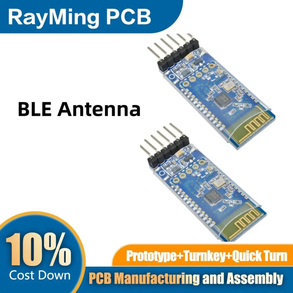
A BLE antenna is a specialized antenna designed to transmit and receive radio frequency (RF) signals in the 2.4 GHz ISM band, specifically for Bluetooth Low Energy devices. These antennas play a critical role in enabling short-range, low-power wireless communication.
1.1 Key Characteristics of BLE Antennas
BLE antennas have several unique characteristics that set them apart:
- Frequency: Operates in the 2.4 GHz band (2.402 – 2.480 GHz)
- Size: Typically compact, often less than 10mm in length
- Power: Designed for low power consumption
- Range: Usually optimized for short-range communication (up to 100 meters)
- Efficiency: High efficiency to maximize battery life in BLE devices
1.2 Functions of BLE Antennas
BLE antennas serve several crucial functions in wireless devices:
- Signal Transmission: Converts electrical signals into electromagnetic waves
- Signal Reception: Captures electromagnetic waves and converts them back into electrical signals
- Directionality: Determines the radiation pattern of the transmitted signal
- Impedance Matching: Ensures efficient power transfer between the antenna and the BLE chip
1.3 Applications of BLE Antennas
BLE antennas are used in a wide range of applications, including:
- Wearable devices (smartwatches, fitness trackers)
- Smart home devices (thermostats, door locks, light bulbs)
- Healthcare devices (glucose monitors, heart rate sensors)
- Asset tracking and logistics
- Retail beacons for proximity marketing
- Automotive (keyless entry, tire pressure monitoring)
Learn More about:
2. Typical BLE Antennas Comparison

There are several types of antennas commonly used in BLE devices. Let’s compare three popular options: micro-strip antennas, metal plate antennas, and chip antennas.
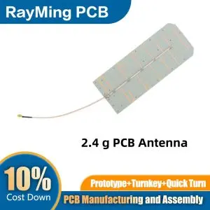
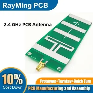
2.1 Micro-strip Antenna
Micro-strip antennas, also known as printed antennas, are fabricated directly on the PCB.
Pros:
- Low profile and lightweight
- Easy to manufacture and integrate
- Cost-effective for mass production
Cons:
- Limited bandwidth
- Lower efficiency compared to some other types
- Performance can be affected by nearby components
Best for:
- Devices with limited space
- Cost-sensitive applications
- Products requiring custom antenna shapes
2.2 Metal Plate Antenna
Metal plate antennas are typically stamped or cut from a sheet of metal and mounted on the PCB.
Pros:
- Higher efficiency than micro-strip antennas
- Good performance in small form factors
- Can be easily customized for specific devices
Cons:
- More expensive than micro-strip antennas
- Requires precise mounting for optimal performance
- May interfere with other metallic components if not properly designed
Best for:
- Devices requiring higher efficiency
- Applications with challenging form factors
- Products where antenna customization is needed
2.3 Chip Antenna
Chip antennas are pre-fabricated, surface-mount components that can be soldered onto a PCB.
Pros:
- Extremely compact size
- Consistent performance across production runs
- Easy to implement with minimal RF expertise
Cons:
- Generally more expensive than PCB antennas
- Limited customization options
- Performance heavily dependent on PCB layout and ground plane
Best for:
- Ultra-compact devices
- Products with rapid development cycles
- Applications requiring consistent antenna performance
2.4 Comparison Table
| Feature | Micro-strip Antenna | Metal Plate Antenna | Chip Antenna |
|---|---|---|---|
| Size | Small | Medium | Very Small |
| Cost | Low | Medium | High |
| Efficiency | Medium | High | Medium-High |
| Customization | High | Medium | Low |
| Ease of Implementation | Medium | Medium | High |
| Consistency | Medium | Medium | High |
3. Materials of BLE PCB Antennas
The choice of materials significantly impacts the performance and efficiency of BLE PCB antennas. Let’s explore the common materials used:
3.1 Substrate Materials
The substrate is the base material of the PCB on which the antenna is fabricated. Common substrate materials for BLE antennas include:
- FR-4 (Flame Retardant 4)
- Most common and cost-effective
- Suitable for many BLE applications
- Higher losses at 2.4 GHz compared to specialized materials
- Rogers RO4350B
- Low loss at high frequencies
- More expensive than FR-4
- Used in high-performance BLE devices
- LTCC (Low Temperature Co-fired Ceramic)
- Excellent for miniaturization
- Good performance at high frequencies
- Used in chip antennas and some high-end devices
3.2 Conductor Materials
The conductor forms the actual antenna element. Common conductor materials include:
- Copper
- Most commonly used
- Excellent conductivity
- Cost-effective
- Silver
- Higher conductivity than copper
- More expensive
- Used in some high-performance BLE antennas
- Aluminum
- Lightweight
- Lower conductivity than copper
- Rarely used in BLE antennas due to size constraints
3.3 Surface Finish
The surface finish protects the conductor and can affect the antenna’s performance:
- ENIG (Electroless Nickel Immersion Gold)
- Good protection against oxidation
- Maintains solderability
- Slightly lower conductivity than bare copper
- Immersion Tin
- Cost-effective
- Good solderability
- May form whiskers over time
- HASL (Hot Air Solder Leveling)
- Traditional finish
- Not suitable for fine-pitch components
- Can affect antenna performance due to uneven surface
4. What is the Range of a BLE Antenna?

The range of a BLE antenna can vary significantly depending on various factors. Understanding these factors is crucial for designing effective BLE systems.
4.1 Theoretical Range
In theory, BLE can achieve a range of up to 100 meters (about 330 feet) in ideal conditions. However, real-world performance is often much less.
4.2 Factors Affecting Range
Several factors influence the actual range of a BLE antenna:
- Transmit Power: Higher power generally means longer range, but also higher energy consumption.
- Antenna Efficiency: More efficient antennas can achieve longer ranges for the same power.
- Environmental Factors:
- Physical obstacles (walls, furniture)
- Interference from other devices
- Atmospheric conditions
- Receiver Sensitivity: More sensitive receivers can detect weaker signals, increasing effective range.
- Data Rate: Lower data rates can achieve longer ranges but at the cost of reduced throughput.
4.3 Typical Ranges in Different Environments
- Open Space: 50-100 meters
- Indoor (residential): 10-30 meters
- Indoor (commercial): 5-15 meters
- Through walls: 5-10 meters
4.4 Extending BLE Range
To extend the range of BLE communication, consider:
- Using external antennas with higher gain
- Implementing mesh networking protocols
- Optimizing antenna placement and orientation
- Reducing environmental interference
5. BLE Antenna Design Guide

Designing an effective BLE antenna requires careful consideration of various factors. Here’s a step-by-step guide to the design process:
5.1 Define Requirements
Before starting the design, clearly define the requirements:
- Size constraints
- Range requirements
- Power consumption limits
- Environmental considerations
- Cost targets
5.2 Choose Antenna Type
Based on your requirements, select the appropriate antenna type:
- Micro-strip antenna
- Metal plate antenna
- Chip antenna
Consider the pros and cons of each type in relation to your specific needs.
5.3 Select Materials
Choose appropriate materials for your antenna:
- Substrate: Consider factors like loss tangent, dielectric constant, and cost
- Conductor: Usually copper, but consider alternatives if necessary
- Surface finish: Choose based on environmental and performance requirements
5.4 Initial Design
Create an initial design based on theoretical calculations:
- Calculate the ideal antenna length (typically λ/4 for 2.4 GHz)
- Adjust for the chosen antenna type and substrate material
- Consider size constraints and apply miniaturization techniques if necessary
5.5 Simulate and Optimize
Use electromagnetic simulation software to model your antenna design:
- Popular tools include CST Microwave Studio, ANSYS HFSS, and ADS
- Simulate key parameters:
- Return loss (S11)
- Radiation pattern
- Gain
- Efficiency
- Optimize the design by adjusting:
- Antenna dimensions
- Feed point location
- Ground plane size and shape
- Matching network components
5.6 Prototype and Test
Once you’re satisfied with the simulated results:
- Create a physical prototype of your antenna
- Test the prototype using a vector network analyzer (VNA) to measure:
- Return loss
- VSWR (Voltage Standing Wave Ratio)
- Impedance
- Perform over-the-air (OTA) tests to verify:
- Radiation pattern
- Gain
- Range in real-world conditions
5.7 Iterate and Refine
Based on the test results:
- Identify areas for improvement
- Make necessary adjustments to the design
- Repeat the simulation, prototyping, and testing process until desired performance is achieved
5.8 Design for Manufacturing
Ensure your final design is suitable for mass production:
- Consider PCB manufacturing tolerances
- Design for automated assembly if applicable
- Ensure compliance with relevant standards (e.g., FCC, CE)
6. What is the Difference Between Bluetooth and BLE?
While Bluetooth and Bluetooth Low Energy (BLE) are related technologies, they have significant differences that impact their use cases and antenna design.
6.1 Power Consumption
- Bluetooth: Higher power consumption, suitable for continuous data transfer
- BLE: Significantly lower power consumption, ideal for intermittent data transfer
6.2 Data Transfer Rate
- Bluetooth: Higher data transfer rates (up to 2 Mbps in Bluetooth 5.0)
- BLE: Lower data transfer rates (up to 1 Mbps in BLE 5.0), but sufficient for many IoT applications
6.3 Range
- Bluetooth: Typically 10-100 meters, depending on the class
- BLE: Similar range to Bluetooth, but can achieve longer ranges at lower data rates
6.4 Latency
- Bluetooth: Higher latency due to connection establishment process
- BLE: Lower latency, ideal for applications requiring quick response times
6.5 Use Cases
- Bluetooth: Audio streaming, file transfer, wireless peripherals
- BLE: IoT devices, wearables, sensors, beacons
6.6 Antenna Design Considerations
- Frequency Band:
- Both operate in the 2.4 GHz ISM band, but BLE uses fewer channels
- Power Efficiency:
- BLE antennas are optimized for low power consumption
- Size:
- BLE antennas are often smaller due to lower power requirements
- Radiation Pattern:
- BLE antennas may be optimized for shorter range, omnidirectional coverage
- Impedance Matching:
- Both require careful impedance matching, but BLE may have stricter requirements due to lower power
Conclusion
BLE antennas are essential components in the growing ecosystem of low-power wireless devices. By understanding the types, materials, design considerations, and performance factors of BLE antennas, engineers and product designers can create more efficient and effective wireless devices.
As the Internet of Things continues to expand, the demand for compact, energy-efficient wireless communication will only grow. BLE antennas will play a crucial role in enabling this connected future, from smart homes to industrial sensors and beyond.
Whether you’re designing a new wearable device, optimizing a smart home product, or developing the next generation of IoT sensors, mastering the intricacies of BLE antenna design will be key to your success. With careful planning, simulation, and testing, you can create BLE antennas that meet the demanding requirements of today’s low-power wireless world while paving the way for the innovations of tomorrow.