It is no surprise that electronic parts manufacturers are the one-stop-shop for your parts needs. But there are so many choices on the market. As a result, it can be challenging to know which electronics manufacturers will serve you best.
For instance, what if you needed a replacement part for your toaster but needed it right away? Your local hardware store is more likely to stock the part. You can have it ready within the hour than an online retailer. From there, it is a matter of driving over to your local electronics parts suppliers. For electronic parts manufacturers, online retailers will also not offer the same level of service.
Most retailers will use a call centre to place the order when you buy online. This can be a helpful tool. But there is no substitute for having someone walk you through the different parts and what they can do.
Another good reason to buy from a local business is that they often have an on-site repair service. This can save you time and money in the long run, especially if your product is under warranty.
Having a business close means you will have more access to publications for electronic parts manufacturers. You will also have access to news stories about the industry. There is no easier way to keep abreast of the industry than through a local business.
Many are looking for no-hassle service and top-quality products. It is in your best interest to go with a local business rather than an online retailer. After all, they have their reputation to uphold beside yours.
History of electronic part manufacturing

We can divide the history of electronic parts manufacturing into three distinct periods.
First golden age
The first golden age of electronic parts manufacturing emerged in the 1950s. This period had significant government funding. There was also a willingness to take risks due to the need for new defence technologies.
But, government funding has declined since 1960. Manufacturers continued to enter the market with new products and services. For example, this period had the development of computer systems. They also developed their peripherals and accessories.
Second golden age
This age of electronic parts manufacturing emerged in the 1980s to 1990s. Also, this period marked the end of the Cold War. This led to continued military spending growth. In turn, it led to a desire for manufacturers to offer a wide range of goods and services.
This golden age has ended, though new technological advances continue to emerge. For example, several area manufacturers are offering e-commerce services on their websites.
Third golden age
The third golden age of electronic parts manufacturing is currently underway. This period continued developing new technologies such as smartphones and tablets. As a result, it created a new demand for electronic parts manufacturers.
Most manufacturers have begun to offer new services geared towards individual users. For example, several retailers and manufacturers offer e-commerce services on their websites.
This also includes businesses that are selling pre-wound electrical coils online. Also, companies are starting to specialize in locating hard-to-find or discontinued items.
Electronic parts manufacturers are also marketing their products via various social media sites. This can save on time and shipping costs for the consumer.
Also, several new technologies allow for faster and more accurate manufacturing processes. For example, several Chinese companies offer applications that can enlarge small objects.
What is new about this golden age?
Several things have changed in the world of electronic parts manufacturing since 2000.
For example, the number of people working in the industry has declined. This is clear when comparing data from the early 2000s with current statistics.
Some businesses have begun to experience a decline in sales. However, other factors may contribute to this problem. They include low advertising costs, strong marketing campaigns, and expanded global markets.
This helps to save on advertising costs and sales growth. Additionally, electronic parts manufacturers can also enjoy an increased focus on e-commerce. This can lead to greater sales and profits.
Other changes include increased automation, which has led to fewer jobs. This may also explain why employment positions continue to decline. In addition, the decline goes with the increase in e-commerce businesses.
Also, many corporations are taking advantage of the benefits offered by e-commerce leads. As a result, they intend to increase competition among electronic parts manufacturers.
Some electronics companies have even taken action to protect their profit margins. However, they do it in the face of this increased competition from e-commerce retailers.
Regulations of electronic components manufacturing companies
Regulations in the manufacturing and selling of electrical parts can be very complicated. This is true when considering the requirements placed on companies by various countries. Also, companies must keep up with different federal standards. They must meet them for their products to reach the consumer market.
You can ensure that it passes specific quality standards before reaching your doors.
The United States government often sets electronic manufacturing regulations. So, those who wish to sell or produce products must follow the safety requirements
Different parts of the country have different regulations. For example, certain states may have rules that apply to specific components. For example, many states recommend using only low-resistance computer cables. This is when dealing with computers and other electronic equipment.
Other states are not so picky about power cables. But they will have different regulations on fluorescent lighting systems and electronic ballasts.
There are essential things companies should do when selling their parts. First, one must make sure that they abide by specific safety standards set by the government. Also, they must get any relevant licenses before selling their products.
Electronic Manufacturing Association
The Electronic Manufacturing Association (EMA) came into being in 1984. The purpose is to promote new technologies and improve the industry. This association connects different electrical components manufacturing company through communication, education and advocacy. The goal of EMA is to ensure that manufacturing continues to remain strong in other regions of the world.
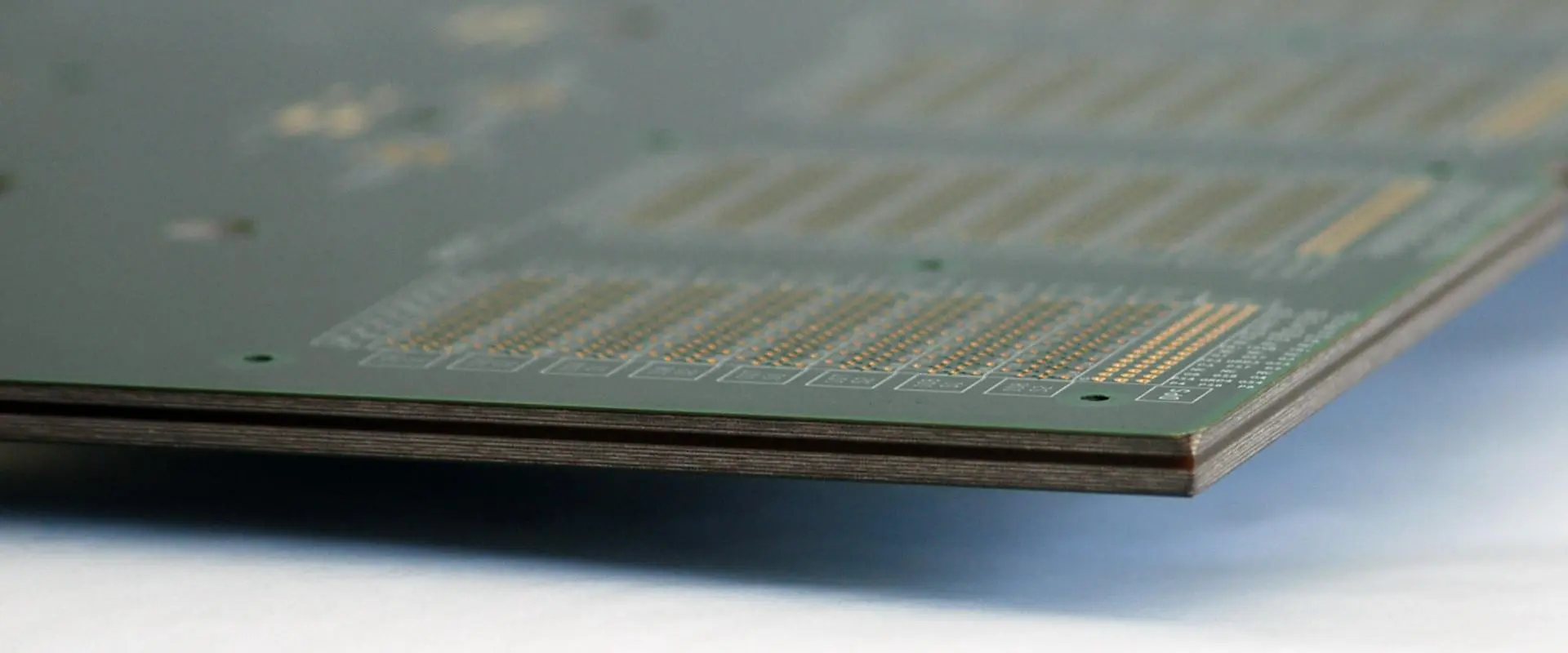
Electronic Components Manufacturers

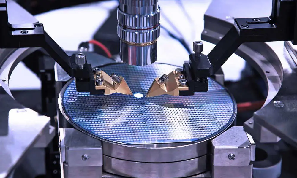
Electronic components manufacturers design and produce a variety of products. They use state-of-the-art technology to deliver products. These products focus on quality, long-lasting performance, and reliability.
Many companies offer various electrical parts. We use the electrical component manufacturers to produce or upkeep essential electronic products. Examples include medical equipment and computer systems.
Manufacturers can also supply various electronic components created for everyday items. For instance, televisions and radios.
Electronic parts manufacturers may also offer a wide range of products and services. For example, they provide information on new technologies. Then they work with retailers to ensure consumers access the best possible prices.
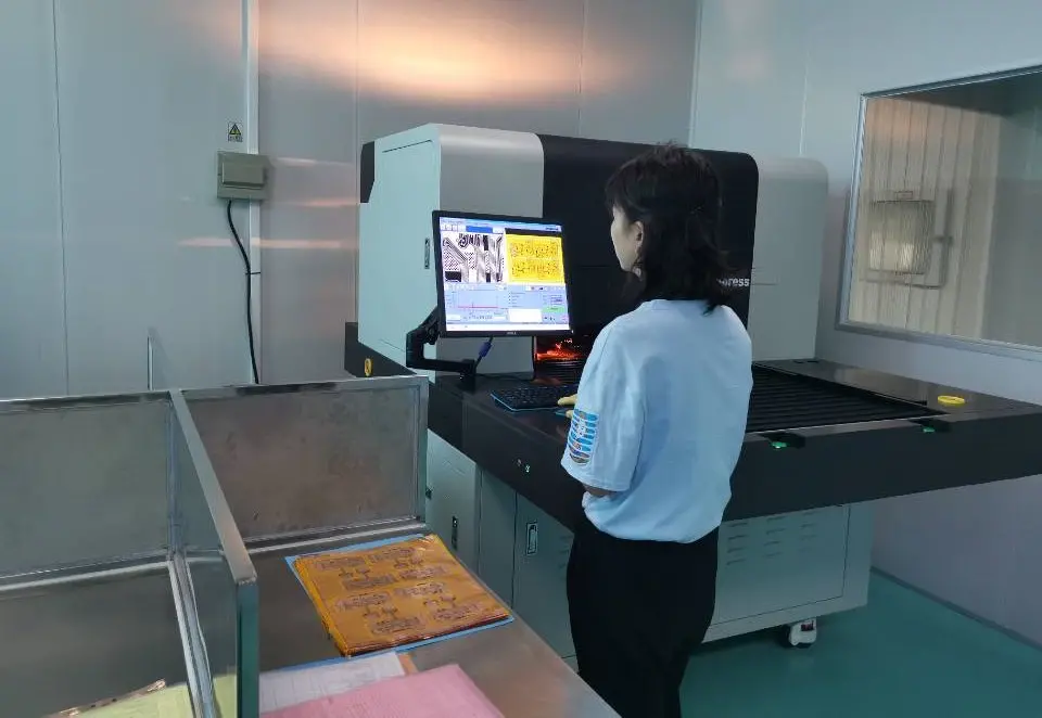
Manufacturers use several different hardware devices. Examples include computers, powerful lasers and tools to meet their customers’ needs. Also, they perform various quality tests on all their products. This allows them to ensure that their products meet appropriate safety standards.
Many of the products made by these companies result from new technologies. However, they also result from new manufacturing processes.
We can find electronic parts manufacturers worldwide in local areas, cities, and towns. Some of them include:
1. Intel Corporation
The Intel Corporation is a leading manufacturer of microprocessors. They also produce other vital items such as motherboards, processors, and memory chips. It is famous worldwide for its quality products. Intel has been supplying most of the world’s electronic components for more than 40 years. It is still the world’s largest semiconductor provider since its start in 1968.
Intel Corporation employs some 100,000 people in the United States. It also has a turnover of more than $43 billion.
Although Intel is a US-based company, it also has locations in other countries. These countries include Israel, Malaysia and China. Also, some of its key subsidiaries are in Canada, Brazil and the Netherlands. Furthermore, the company is currently working on significant projects in Taiwan and Vietnam.
Their main products are flash memory-based components. These have become a vital part of the world’s electronic systems.
Also, their products are helpful in many other popular systems. These systems include mobile phones, digital cameras and MP3 players. The company has also developed several different devices. For example, they help with voice-recognition software and digital photography.
Also, Intel has established various research and development centres worldwide. This helps them focus on new technologies. However, they also focus on products related to their existing line of goods.
2. Information Storage Technology (ISOTECH)
ISOTECH offers a wide range of electronic parts and components. We use them in various electronic devices and systems. The company creates many items, including capacitors, rectifiers, resistors, and integrated circuits. Their products are essential in several different ways for many industries. They include telecommunications and consumer electronics. ISOTECH has also made several contributions to the computer industry.
We can find ISOTECH in the United States and has several facilities worldwide.
The company’s main facility is in Joliet, Illinois and employs some 1200 people. The factory produces components used in televisions, personal computers and other electronic gadgets. ISOTECH also has a global presence through its subsidiaries. Its main site is in Taiwan, but it also has branches in Australia and the United Kingdom.
The manufacturers founded ISOTECH to supply semiconductor and electronic components. But, it did not start as a full-scale manufacturer and distributor. It only began to produce its products in the 1990s.
The company is currently developing new memory storage components. They include Rambus DRAM products and Static RAM. Also, ISOTECH is an industry leader in producing innovative high-frequency powers. Some of them have the Discrete Integrated Circuit.
3. Integrated Silicon Solution Inc.
Mian Quan Sheng founded Integrated Silicon Solution in 2002. It is a leading provider of electronic components for the aerospace industry. ISSI has an impressive history of growth. It has strategic moves from senior management have backed.
ISSI has two leading factories and two production bases located in China and Vietnam. These sites have over 2000 of the company’s most experienced employees. ISSI focuses on aerospace technology. It is a leading provider of high-reliability products used in military technology. They also produce products used in commercial applications.
ISSI has some very strong relationships with many of its key customers. Some include Airbus, Boeing and Lufthansa Technic.
ISSI’s main products include high-reliability integrated circuit chips. We use them to produce network and computer systems. ISSI also provides components for many other applications. Examples include medical technology and satellite communication.
The company would supply electronic components to the aerospace industry. But, ISSI has grown into one of China’s leading electronic parts suppliers of advanced circuitry.
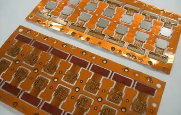
4. Rayming PCB & Assembly
Rayming is a leading electronic manufacturing services provider. The company offers a wide range of electronic parts and components. We use them in many popular electronic products throughout the world.
Rayming has been in operation for over 15 years. It currently has six locations in China, each employing some 300 staff members. The company also has branches in Taiwan, Japan and the United States. Its main site is Rayming Industrial Area, Guangzhou City, Guangdong Province.
The manufacturers established Rayming to supply electronic parts and components. But, to boost the business growth, the company began to buy electronic companies. Its management believes that is an excellent way to build a solid supply base.
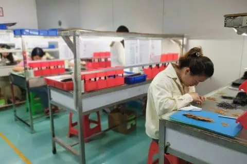
Today, Rayming PCB & Assembly is an ISO certified service provider. They have a group of excellent engineers. They help the company meet the needs of customers from across the globe.
Their main products are in demand worldwide. They include resistors, capacitors, integrated circuits, connectors and other vital items. Also, the company provides services related to new product development. In addition, they also make PCB design and final assembly of various types of electronic systems.
5. Silicon Laboratories
Silicon Laboratories Inc. is a leading designer and manufacturer of high-performance analogue and mixed-signal integrated circuits.
The company started operations in 1997. Currently, it has seven research and development facilities. You will find them in the United States, China, India, Taiwan, Korea, the United Kingdom and Israel.
Silicon Laboratories employs a team of 1300 skilled people. They dedicate themselves to producing integrated circuit chips. They can help develop new electronic products such as wireless communication devices.
Silicon Labs is also a leading provider of wireless and RF solutions for the global market. The company offers several different wireless chips. In addition, they are helpful for various other applications.
Silicon Laboratories also provide technology and support to its customers. As a result, they ensure that they can enjoy their products.
6. Samsung Semiconductor, Inc.
Samsung is a leading producer of semiconductor products. Some include discrete devices, memory products, and integrated circuits. Also, Samsung offers a wide range of different chip hardware types. As a result, we use them in many other high-tech electronic goods.
Samsung has been operating in South Korea since 1969. The company is one of the largest producers on earth. It provides a wide range of products related to micromachines and electronics. Its main products include semiconductors, LCDs, mobile phones, home appliances and memory devices.
Samsung currently has three locations. They are in South Korea and one in the United States. The company also operates several research and development facilities. You will find them in the Republic of Korea, Taiwan, China and Japan.
SSI employs around 3500 skilled people. They help the company improve its selling power and achieve tremendous success.
7. Qualcomm
Qualcomm is a leading provider of digital wireless telecommunication products. The company is in the United States. It is one of the world’s largest producers of chips for telecommunication equipment.
Today, Qualcomm has offices located in some 30 countries around the world. The company also has several sites in the United States, China, India and Europe. These sites have over 5500 skilled people. They help the company develop new technology. This, in turn, will help it achieve tremendous success.
Qualcomm’s main products include wireless communications chips and systems. We use them in various applications, such as mobile phones and portable media devices. Also, Qualcomm provides a wide range of different solutions. As a result, it helps make the world a more connected place.
8. SK Hynix Inc
This is a leading provider of semiconductors used in a wide range of different products. They include mobile phones and computer systems. Also, SK Hynix offers products used to develop various applications.
The company has an impressive history. They developed it through strategic moves made by senior management at the company.
It has offices and manufacturing facilities based in South Korea and Taiwan. Each of these locations has a workforce of around 3,000 people. They help the company improve its selling power and achieve tremendous success.
Its main products include high-density memory solutions and mobile DRAM chips. These products are helpful in many different applications.
9. Toshiba Corporation
Toshiba is among the leading electrical components suppliers. It also produces LCD screens and components for the electrical industry.
Toshiba Corporation is in Tokyo, Japan, and established in 1875. The company has operations in over 60 countries worldwide. It currently has its main offices located in Tokyo.
Toshiba has a long, proud history that dates back to the early days. It is when telecommunications first began to produce telephone equipment. As a result, the company has developed various products and services. They do so by taking advantage of the latest advances in technology.
Toshiba has a workforce of around 200,000 people. They help the company improve its selling power. This leads to achieving greater levels of success.
10. Texas Instruments Inc
TI is one of the leading providers of semiconductor products. The company also has a wide range of other electronic goods used in several applications.
The TI family of companies is one of the most diverse and significant organizations. As well as its main business activities, TI also has many side businesses. For example, they take part in research and development projects.
TI operates around 100 offices in over 38 countries. The majority of them are in the United States and Japan. Each of these locations has a workforce of over 20,000 skilled people. They help the company achieve greater levels of success.
The company’s main products are ICs and RF transceiver chips. These products can create various applications. They include mobile phones, digital cameras, and PCs.
11. Broadcom Inc.
Broadcom is one of the leading providers of semiconductor solutions. They focus most on wireless communications. They also deal with infrastructure markets. The company has a wide range of solutions. We use them in mobile telephones, wireless equipment, and set-top boxes.
Broadcom has had its offices in the United States since 1965. It has experienced rapid expansion during the past few years.
The company’s headquarters are in Irvine, California. Also, Broadcom provides a wide range of products. For example, we use them to develop WiMAX and voice processing products. Broadcom employs around 15,000 people.
12. Lenovo Group
Lenovo is one of the world’s leading manufacturers. They produce personal computers and mobile devices. The company has offices worldwide. It is one of the leading brands in the global technology industry.
The business started in China in 1984. It has grown from a small start-up to become a significant manufacturer. They are now present in over 70 countries worldwide.
Today, Lenovo Group has its main headquarters located in Beijing, China. The company has an impressive workforce of around 40,000 employees. They help the company achieve greater levels of success.
The company’s main products include desktop, notebook and tablet PCs, and mobile phones. The company also provides many cloud-based services to its corporate customers.
13. Micron Technology Inc.
Micron Technology is one of the leading manufacturers of semiconductors devices. They include flash memory storage and DRAM products. We use them in a wide range of different electronic products.
Micron Technology started in Idaho, United States, in 1978. It began as a joint venture between Israel’s Elbit Systems Ltd. and America’s IM Flash Technologies Inc., now known as Micron Technology Inc. They then renamed the company following a buyout by Micron Technology Inc. in May 1989. The company has an impressive workforce of around 10,000 people.
14. TE Connectivity
TE Connectivity develops a wide range of products for the global electronics industry. The company’s headquarters are in the United States. It has operational offices worldwide.
The company provides the highest quality and service to its customers. The company has a workforce of around 53,000 workers. They help the company achieve greater levels of success.
15. CFM International
CFM is the world’s leading manufacturer of large commercial jet engines. They are essential for the business aviation industry. The company also develops a wide range of place engines. We use them in military and regional applications. Additionally, they work in maritime patrol and surveillance planes.
CFM International has its main headquarters located in Connecticut. The company has an impressive workforce of around 77,000 people.
Conclusion
Due to their size and dominance in the electronics industry, the top ten companies listed above have an enormous influence on the global market. The top listed here have revenues which account for a significant part of the total worldwide sales figures.
The technology sector continues to mature, and we are only beginning a new era. In the future, we will see many more venture capital-funded companies emerging. It will ensure plenty of room in this market for all businesses.