Introduction
Digital circuits are the fundamental building blocks of all electronic devices and systems around us. From smartphones, computers, TVs, automobiles to industrial automation systems – all employ digital circuits extensively for processing and controlling digital signals. This article provides a comprehensive introduction to digital circuit design concepts including working principles, common logic families, major types and applications with example circuits.
How Digital Circuits Work
Digital circuits operate on discrete signal values representing binary 1s and 0s, in contrast to analog circuits handling continuously variable signals. The basic working principle involves:
- Representing information as binary digits (bits)
- Using logic gates like AND, OR, NOT to process the bits
- Combining gates into complex circuits to perform functions
- Using binary arithmetic for mathematical operations
Digital signals have only two definite levels – high/low, on/off, true/false – corresponding to logic 1 and 0. Circuits detect and regenerate these logic levels reliably allowing complex processing using simple Boolean logic.
Digital circuits use electronic switching between saturated states to implement logic functions. Transistor or diode switches change between cutoff and saturation rapidly to recreate sharp digital transitions. Positive feedback ensures unambiguous operation.
Digital Circuit Advantages
Key advantages of digital circuits that have made digital systems ubiquitous:
- Discrete states – Easier to distinguish between a limited set of states compared to analog
- Noise immunity – Regeneration of digital levels provides noise margin up to ±30%
- Scalability – Large systems can be integrated by combining smaller logic blocks
- Flexibility – Reprogramming digital systems allows multiple functions from the same hardware
- Reliability – Digital error detection and correction improves reliability
Logic Gates
Logic gates are elementary building blocks of digital circuits that perform basic Boolean logic operations on one or more input signals to produce a single output.
Common single-bit logic gates and their operation tables are:
NOT Gate
Inverts the input signal. Output is HIGH if input is LOW and vice versa.
| Input | Output |
|---|---|
| 0 | 1 |
| 1 | 0 |
AND Gate
Output is HIGH only when all inputs are HIGH, else output is LOW. Performs logical conjunction.
| Input 1 | Input 2 | Output |
|---|---|---|
| 0 | 0 | 0 |
| 0 | 1 | 0 |
| 1 | 0 | 0 |
| 1 | 1 | 1 |
OR Gate
Output is HIGH if any input is HIGH, else LOW. Performs logical disjunction.
| Input 1 | Input 2 | Output |
|---|---|---|
| 0 | 0 | 0 |
| 0 | 1 | 1 |
| 1 | 0 | 1 |
| 1 | 1 | 1 |
XOR Gate
Output is HIGH if inputs are different, LOW if they are the same. Performs exclusive disjunction.
| Input 1 | Input 2 | Output |
|---|---|---|
| 0 | 0 | 0 |
| 0 | 1 | 1 |
| 1 | 0 | 1 |
| 1 | 1 | 0 |
NAND Gate
AND gate with inverted output. Output is LOW only if all inputs are HIGH.
NOR Gate
OR gate with inverted output. Output is HIGH only if all inputs are LOW.
These basic gates are combined in complex ways to implement all digital logic functions.
Logic Families
Logic gates are constructed using different transistor-level circuit families based on factors like speed, power, cost, and integration scale. Popular logic families include:
Transistor-Transistor Logic (TTL)
Uses bipolar junction transistors (BJT). Provides high speed, high current drive and good noise immunity. 5V standard TTL is the most common.
Complementary Metal Oxide Semiconductor (CMOS)
Uses complementary n-type and p-type MOSFET pairs. Very low power consumption but higher propagation delay. 3.3V or 5V supply. Can integrate high density circuits.
Emitter Coupled Logic (ECL)
Uses BJTs with constant current source biasing. Provides very high speed but consumes more power. Ideal for high performance circuits.
N-type Metal Oxide Semiconductor Logic (NMOS)
Uses n-channel MOSFETs. Simple construction but higher power loss. Used in early microprocessors.
Gallium Arsenide (GaAs) Logic
Uses GaAs field effect transistors. Very high speed suitable for microwave operations up to 12 GHz. Used in high frequency ICs.
Classification of Digital Circuits
Digital circuits can be classified based on their logical function as follows:
Combinational Circuits
Consist of logic gates where the output is determined solely by the present combination of inputs. Do not use memory or feedback. Example: decoders, multiplexers, parity checkers.
Sequential Circuits
Use memory elements in addition to logic gates. Output depends on present inputs as well as past inputs. Examples: flip flops, counters, shift registers.
Based on construction, they are classified as:
Fixed-Function Circuits
Consist of standard logic gates designed to provide specific function. Less flexible but simple to design. Example: an adder constructed from gates.
Programmable Logic Devices (PLD)
Consist of AND-OR gate arrays that can be interconnected by the designer. Provides flexibility and customizability.
Application-Specific Integrated Circuits (ASIC)
Custom ICs optimized for a specific task like a microprocessor. Highest performance but expensive.
Major Types of Digital Circuits
Some major types of digital circuits used extensively in most digital systems are:
Multiplexers and Demultiplexers
- Multiplexer (MUX): Takes multiple inputs and selects one to forward to output based on a control input.
- Demultiplexer (DEMUX): Routes single input to one of many outputs based on control.
- Allows efficient sharing of transmission lines and interfaces.
Decoders and Encoders
- Decoder: Converts binary encoded inputs to associated outputs. Enable parallel control lines using fewer selection lines.
- Encoder: Converts multiple input lines into encoded binary outputs. Reduces number of transmission lines.
- Commonly used in memory addressing and 7-segment displays.
Flip Flops
Bistable multivibrators that store one bit of data. Widely used in registers, counters, memory. Types include SR, D, JK, and T flip flops.
Shift Registers
Consist of flip flops connected together enabling moving stored data serially. Used for converters, buffers, delay lines.
Counters
Consist of flip flops configured as frequency dividers or sequence generators. Used in timers, digital clocks, frequency meters.
Adders
Used to perform binary addition and subtraction. Half and full adders are the basic building blocks for arithmetic logic units in CPUs.
Comparators
Compares two binary values or magnitudes and determines their relation like equal, greater than, less than. Essential in analog-to-digital converters.
Schmitt Trigger
Provides input noise filtering and waveform shaping using positive feedback. Converts slowly changing signals into sharp transitions.
Digital Circuit Applications
Digital circuits serve as the basis for implementing a wide variety of useful applications and electronic systems.
Computers and Processors
Microprocessors, microcontrollers, RAM, peripherals are built using digital circuit blocks including registers, ALUs, clock circuits.
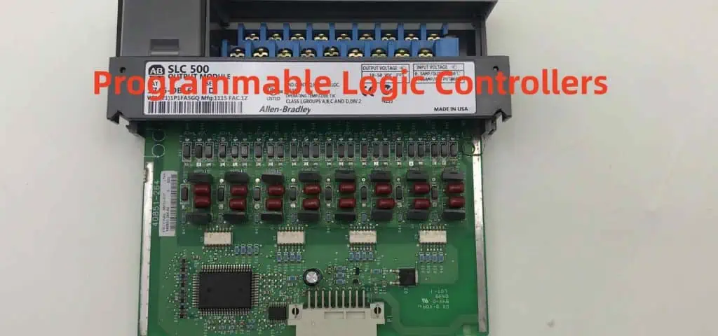
Programmable Logic Controllers
PLCs use integrated digital circuits to provide robust automated control for industrial processes like assembly lines.
Calculators
Perform mathematical operations electronically using arithmetic logic units, display drivers, memory chips.
Digital Displays
Seven segment, dot matrix LED/LCD displays are interfaced using decoder, driver and controller circuits.
Wireless Communications
Digital data modulation, encoding, sequencing is performed in radios and cellphones using logic circuits.
Automotive Systems
Digital circuits drive engine control modules, airbag controls, infotainment systems, GPS units in modern vehicles.
Home Appliances
Washing machines, air conditioners, smart TVs use microcontrollers and logic circuits for programmed operation.
Traffic Light Controllers
Timing circuits like oscillators, counters and flip flops help sequence traffic signals.
IoT Smart Devices
Internet connected devices use logic circuits for local processing and telemetry control.
Medical Electronics
Monitoring equipment, implantable devices rely on precise timing and control circuits.
Space Systems
Digital circuits provide computation, sequencing and control for spacecraft onboard systems with low weight and power needs.
Military Systems
Guidance systems in missiles, rockets and torpedoes employ radiation-hardened digital circuits for accurate control.
Examples of Common Digital Circuits
Half Adder
Adds two single bit binary numbers A and B. Uses XOR gate for sum and AND gate for carry out.
RS Latch
Simple flip flop made of two cross-coupled NOR gates to store one bit. R=1 resets output Q=0, S=1 sets Q=1.
Binary Counter
Counts pulses using JK flip flops connected in toggle mode. Output increments on each clock edge.
2 to 4 Line Decoder
Converts 2-bit input to 1-of-4 output lines to select devices. Enable controls overall operation.
DAC – R2R Ladder
Uses resistor ladder network to convert digital input to analog voltage output proportional to code.
Schmitt Trigger Inverter
Provides hysteresis for clean switching of noisy input using positive feedback via resistor Rf.
Conclusion
Digital circuits offer advantages of noise immunity, scalability and flexibility for implementing logic, arithmetic, sequencing and control functions in electronic systems. Combinatorial and sequential logic circuits built from standard gates and flip flop provide building blocks for designing complex digital systems. Continued progress in IC fabrication allows packing billion-transistor ultra-high density circuits enabling today’s digital products and infrastructure.
Frequently Asked Questions (FAQs) about Digital Circuits
Here are some common questions about digital circuits:
Q: What is the difference between analog and digital circuits?
A: Analog circuits operate on continuous signals with infinite values. Digital circuits operate on discrete ON/OFF signal values of 0 and 1.
Q: What are the basic building blocks of digital circuits?
A: Logic gates like AND, OR, NOT that implement fundamental Boolean logic are the basic building blocks of digital circuits.
Q: What are the advantages of digital circuits over analog circuits?
A: Key advantages are noise immunity, easier scalability, flexibility through programming and higher reliability using error correction.
Q: What are combinational and sequential logic circuits?
A: Combinational circuits provide output based only on current inputs. Sequential circuits use memory elements where output depends on past inputs too.
Q: What are the different logic families used in digital circuits?
A: Popular transistor-level logic families are TTL, CMOS, ECL, NMOS, GaAs logic. Each optimizes factors like speed, power, density, and cost.
How Digital Circuit Works
Have you ever wondered what happens when you flip a switch and turn on a light? How does that electrical signal travel from the wall to the bulb, and what makes it work? What do you achieve when you flip a switch?
You don’t need to wonder any longer! The circuit is an interactive computational tool. It helps you explore how to translate analog electrical signals into digital signals and back again. Start by exploring the circuit shown below. We connect the source, or power source (a battery), to a circuit by a light bulb or bulb socket. Then turn the switch on to see what happens.
A circuit is in many ways similar to the electrical circuits you use every day. The difference is that the electricity flows in an electrical circuit in a continuous loop. In contrast, the electricity flows with a series of switches and electronic components in an analog circuit.
An analog electrical signal is a voltage (like static electricity) that you can turn on and off. That’s why you sometimes hear about something being ‘on/off’ or ‘high/low.’ In your home, there are switches on at least some of your lights.
What is a digital circuit?

A digital circuit is an electrical circuit that uses binary logic to process binary data. The term ‘digital circuit’ is usually used interchangeably with ‘digital logic circuit.’
A digital circuit processes binary data composed of two discrete values. We represent them by the numbers 1 and 0. Binary data is the language of computers and other digital devices. Examples include calculators, mobile phones, and cars diagnostics computers.
Digital circuits are the basis for all modern computing. You will find them on LCD screens and lights on different devices. These devices include automobiles, cellular phones, and appliances.
The digital circuit is in every digital device. These electronic devices use binary logic circuits that process digital data. Popular examples include digital switches and counters in all computer applications.
The blue circuit consists of the switch, the light bulb, the capacitor, and the resistor. The red circuit consists of two wires. We connect the switch to one wire using an electronic component called a ‘toggle switch.
How does Digital Circuit work?
There are two common types of digital circuits: combinational logic and sequential logic.
Digital circuits consist of logic gates that use binary signals for their inputs. These are the red and blue wires found in the circuit. The output of a logic gate is either 0 or 1. It corresponds to a voltage’s absence or presence (a ‘low’ signal or a ‘high’ signal). If a wire carries a ‘low’ signal, you may connect it to the ground without changing the circuit’s operation. All inputs are either high or low signals.
The CPU occupies a central role in modern computers and other digital devices. The (CPU) performs calculations based on the binary data that it receives. One type of CPU is the modern microprocessor. It contains millions of transistors that Rayming PCB & Assembly to process trillions of binary bits in parallel.
Transistors help build logic gates that act as switches to turn signals on and off in digital circuits. They act as a transistor in an amplifier that we can either turn ‘off’ or ‘on.
The digital gates are physical chunks of semiconductor silicon that act as electronic switches. The ‘on’ state is binary 1, and its ‘off state is binary 0.
Each switch in each circuit in a computer can be either on or off. Likewise, each transistor in an integrated circuit can be either on or off. They are both on, but one is lower than the other. This binary data move conductive wires, the transmission medium for binary instructions.
Types of Logic Circuits
We connect the logic gates in the circuit using a combination of wires and transistors to form a logic gate. Then, the output of one logic gate connects to the input of another logic gate, producing a chain reaction.
This chain reaction is a series of ‘on’ and ‘off’ signals. These signals travel from one end of the circuit, lighting up the light bulb. Of course, the details will vary from one type of digital circuit to another. But all digital circuits use variations on this basic principle.
They obey logic rules similar to math, such as the ‘AND’ and ‘OR’ logic rules. However, the input is only considered true in digital logic if all inputs are true. In this case, we consider the output true only if both 2 and 3 are true. This is because both A and B had to be on simultaneously for this to happen.
1. Combinational Digital Logic Circuit
Combinational circuits are the most common type of digital circuit. They can perform simple arithmetic and logical operations. Such operations include addition, subtraction, multiplication, and division. They depend on logic gates such as NAND gate, NOR gate, NOT gate, AND gate, an OR gate.
Combinational digital logic circuits can perform repetitive tasks without any external clock signal. Instead, the circuit itself provides the clock by resetting its state after a set period.
Computers are examples of combinational digital logic circuits, as are the following objects:
- Digital clocks, alarm clocks, and timers (with an interval timer)
- Light dimmers
- Electronic thermometers
- Automatic doors and windows controllers
2. Sequential Digital Logic Circuits
Sequential circuits are digital logic circuits. They change state after a timed period in response to a triggering event. For example, they respond to triggers such as the flip of a switch or the rising or falling edge of a clock signal.
Sequential digital logic circuits include memory (storage) elements. Good examples include flip-flops, latches, and registers. They are essential in modern computers. This is because they store information while performing tasks in other system parts. As a result, the device’s output does not depend on the input values but rather the device’s current state.
Sequential circuits consist of digital logic gates and memory devices. They can perform repetitive tasks at timed intervals, such as an alarm clock or television that turns on at a specific time.
Computers are also helpful for sequential digital logic circuits, for example:
- Televisions
- Cash registers
- Digital clock
- Alarm clocks
- Telephone handsets
Digital clock machines use sequential digital logic circuits to store the time and set the time.
3. Circuits with Clock-Driven Components
Digital logic circuits can also synchronize with the clock that controls their operation. This produces digital pulses at regular intervals, just like an analog clock.
Digital circuits that respond to a regular pulse are periodic or synchronous.
Circuits can run together or parallel and synchronize their behavior with the same clock pulses. But, first, we connect all clock lines and attach them to a common output line or wire.
We often clock together two or more digital circuits that use the same clock signal.
When a common clock signal clocks a circuit, we call it a synchronous circuit. In this book, we will only discuss synchronous digital logic circuits.
An example of an asynchronous digital logic circuit is an asynchronous RAM. It consists of flip-flops connected in parallel. This enables the system to read and write all of them simultaneously.
4. Circuits with Event-Driven Components
Instead of a clock, circuits can react to an external or internal signal or event. We refer to these event-driven digital logic circuits. An event-driven circuit responds only when the triggering condition is present. It ignores all other input signals during that time.
Difference Between Analog Circuit and Digital Circuit
Both circuits serve a vital role in electronics and are an integral part of electronics. In addition, both circuits help process information in digital hardware. It uses binary numbers instead of analog hardware that uses continuous values.
Digital circuit processing is faster than analog circuits. However, digital circuits require more power. Therefore, Digital circuits have their merit and demerits. They are widely helpful in different fields of electronics.
Circuits are a building block for any electronic device or system. So, the study of circuits is very significant for a person who will make electronic systems.
Analog Circuit
An analog circuit is a circuit in which the information moves through varying physical quantities. These quantities include electric charge, current, magnetic flux, etc.
The word analog comes from the Greek word analogos (αν λος), meaning “proportionate,” “corresponding to.”
Analog circuits help control physical processes such as amplifying a signal or filtering noise out of power lines. In addition, the analog circuit efficiently handles processes where large amounts of data need processing, and other signals change over time.
Analog circuits are helpful in process control, temperature sensors, and video systems.
Analog circuits are always helpful in varying the value of a variable (voltage or current) applied to the points in the circuit. The continuous variation of voltage (or current) makes it look at a continuous function.
Digital Circuit
A digital circuit is an integrated circuit (IC) used in computers to store data. We can consider it a mini-computer. A computer system needs a storage unit, which acts as a storage and processing power medium. This storage unit could be in the form of a magnetic disc, optical disc, or paper tape.
The problem with these previous methods is that they are mechanical. Therefore, they can also fail due to mechanical factors such as heat, shock, etc.
Digital circuits overcome this problem by using electrical switches to store the data. The transistors control these switches, which store or release electrical power.
The binary data is not stored directly in a digital circuit. Instead, we convert it into a series of ones and zeros, called bits (short for “binary digits”). Combining these bits allows you to write numbers on a computer the same way you write letters on paper.
Digital circuits have some advantages over analog circuits.
Features
1. O/P Quality
Analog-to-digital converter (ADC) is the first conversion stage from an analog signal to a digital signal. An analog-to-digital converter requires extensive calibration for sufficient precision and accuracy. An ADC acts as a standard simulator and tests various systems. They work best in measurement instrumentation, medical devices, etc.
Digital circuits are more helpful due to their ease of use and precision in data handling.
2. Efficiency of a Circuit
Analog circuits in use depend on rheostat (an indirect variable) & potentiometer (direct variable). A variable resistor or potentiometer helps adjust the output of an analog circuit. Digital circuits do not need a variable resistor or potentiometer. They control electrical signals directly. Due to their nature, digital circuits are more efficient. They need less power than analog circuits.
3. Precision and Reproducibility
Digital circuits are more precise and reproducible than analog circuits.
When we convert analog signals to digital form, we capture the imperfection in the original signal by sampling. However, Digital signals do not capture this imperfection as in the original signal. Therefore, digital signals are helpful in highly accurate measurements and industrial control applications. For example, level sensing with a level transmitter is very accurate.
Main Differences
• Analog circuits process information continuously, while digital circuits process information in steps.
• Analog circuits use continuous signals instead of digital. It uses “on” and “off” signals.
• Analog circuit is always used by varying the value of a variable (voltage or current) applied to the points in the circuit. The continuous voltage variation appears to be looking at a continuous function. While in digital circuit processing, a binary number helps represent a number between 0 and 1.
• 2-state Digital circuits do not have the problem of function approximation and noise.
Channel
A channel is a component that allows you to connect signals to your circuit.
There are two types of channels in digital circuits: input and output. Digital buses are essential for the connection to other electronic devices. Therefore, your circuit’s input and output channels can connect to other electronic devices. We use CMOS logic levels & serial communication to achieve this.
Mixing Analogue and Digital
We can conduct the digital and analog worlds together through an analog-to-digital converter. One can convert a digital signal into an analog binary code. The ADC converts the analog signal into a digital signal. We can then process these signals further by a digital circuit.
Ground Noise:
Ground noise is also known as a ground loop. It is a type of noise that occurs in mains supply and ground wires. Nearby appliances and electric motors can cause this noise. A ground loop can cause random digital output values on the circuit. It is similar to the “crosstalk” problem.
Once we make the circuit, it is essential to ensure no ground loops. It is usually impossible to remove the ground loop entirely. Therefore, it ensures no components in the line path of any power supply wires can help solve this problem. It’s usually essential to install a separate ground wire for each power supply wire. Placing the ground wire away from the power supply wires and components such as switches and relays is the best practice.
One signal goes from the A input (microcontroller) to the digital bus. Then, other devices connected to that bus receive this signal. Finally, this signal then goes back to the A input of the microcontroller for processing and storage.
Filtering:
We filter out the noise caused by all connected devices (i.e., mains supply). In addition, filters help to exclude noise in the output signal. There are different kinds of filters depending on their application. But all filters will have low pass (LP), high pass (HP), and bandpass (BP) characteristics.
It is important to note that filters can affect the characteristics of the circuit. Therefore, we must choose them in this regard. It is best to select a filter that can provide a large bandwidth with a low attenuation rate.
Single-Board Systems:
Single-board systems are the simplest type. They have all the components attached to a single circuit board. This means that all of the components connect. To achieve this, you must isolate the board itself. You will achieve isolation using copper planes, plastic planes, or both. It is important to note that isolation must be good enough. It helps to avoid short circuits occurring between grounds on the board.
Multichip Systems:
Multichip systems are more complicated than single-board systems. This is because they have more than one circuit board. For the boards to communicate (i.e., send/receive signals), they need a physical connection. You must make this connection using a copper plane and connecting both boards. For example, a ribbon cable could transmit the signal from one board to the other. However, using a copper plane is not ideal for multiple boards. This is because of the added difficulty in routing these planes between the components.
Multichip systems are commonly helpful in large-scale projects. They allow you to separate your system into different sections. In addition, it makes maintenance and service easier.
Single-board systems require less hardware and are good for smaller-scale projects.
Multi-Board Systems:
These systems have multiple circuit boards and use cables to connect them. The advantage of this is that you can tailor each system to a specific application. In addition, they use a bus (a common connection) to connect all of the boards. We can use the bus for control and signal transfer between devices.
Analog-to-Digital Conversion (ADC)
The conversion of analog, continuous signals to discrete data is Analogue-to-Digital Conversion. We do this using an ADC (analog to digital convertor). The ADC takes the analog signal and converts it into a digital code. The greatest advantage of an ADC is the more accurate has lower noise. It also has a higher resolution than digital data can be.
Digital-to-Analogue Conversion (DAC)
The conversion of discrete binary data into continuous analog signals is Analogue-to-Digital Conversion. We do this using a DAC. The DAC takes the digital data into a continuous analog signal. The great advantage of a DAC is that you can make changes to data.
ADC Vs. DAC
An ADC converts a continuous analog or digital variable (resolution) signal to digital number series. On the other hand, a DAC converts digital number series into a continuous analog signal.
The output amplitude & frequency of an ADC relates to the input analog value or digital code. That of a DAC relates to the value of the digital code.
CMOS Vs. TTL
The CMOS vs. TTL is an internal signal level of a digital circuit. CMOS stands for Complimentary Metal Oxide Semiconductor. It is an alternative to the basic standard and older TTL (Transistor-Transistor Logic). A CMOS device can use a smaller power supply voltage and longer integration time. The output voltage for a CMOS device is higher than that for a TTL device. A TTL device uses a low power supply voltage and has shorter integration times than CMOS devices. A TTL device can be essential for applications that need a short response time.
Integrated Circuits (IC)
An integrated circuit is a small electronic component that can perform several functions. An IC enables you to design and develop digital circuits using one component. This is instead of using several individual components. The small size makes it suitable for use in large systems.
Programmable Logic Devices (PLD)
A programmable logic device (PLD) is a device that sometimes we call an programmable array. It is a microprocessor-like circuit. It allows precise control of multiple functions through programming. PLDs are often helpful with microprocessors as system controllers. Therefore, E often uses the terms programmable and logic. We use it when referring to PLDs and microprocessors. However, the specific implementation of a programmable logic device is different. There are several differences compared to that of a microprocessor in many ways.
Conclusion
The use of digital electronics has revolutionized our modern way of life. Computer systems are everywhere. They are a necessity in almost every single industry. The digital interface has made communication and control easier. Digital circuits are helpful in many ways to control simple devices. We can even use it to solve complex tasks. Digital electronics is a vast field. It is always expanding and evolving. The characteristics of digital circuits make it very easy to convert analog signals into discrete data. These conversion techniques are essential in many applications. The most common is to convert analog signals into digital data using an ADC or DAC.
Furthermore, we can convert this data back into an analog signal using a DAC or ADC. However, before converting the analog signal back into a digital signal, you need to configure the components of the circuit. It is best to select a filter that can provide a large bandwidth with a low attenuation rate.