Full Introduction about QuickLogic ArcticLink III Family

QuickLogic ArcticLink III

Mediums are not just for storing or transmitting information. They can act as physical representations or interpretations of an experience. This post will examine how we conceptualize sound through mediums. They include airwaves, recordings, songs, and instruments.

QuickLogic ArcticLink III Family is relevant to this topic because it makes creating and using music a lot easier.

It is also relevant because this post is not only an introduction to QuickLogic ArcticLink III Family. It is also a means of understanding the actual nature of music. I want to understand how we create music, listen to it, and create sound out of any experience.

The ArcticLink III Family

ArcticLink III Family by QuickLogic is a small, cost-effective development board. It combines analog signal processing with digital signal processing into a single package. The board consists of a fully-programmable Analog Devices ADSP2100 DSP, a 64-pin QFP package. They contain 512KB of flash memory, and 256KB of SRAM from Atmel, an Atmel AT91SAM7S ARM7TDMI processor.

The board is fully programmable, but it is only suitable for 16-bit DSP functions, not 24-bit. This does limit the number of voices that a single chip can generate without using more chips. The software package provided by QuickLogic includes code for a basic synthesizer. However, it is entirely open-source so that you can program any instrument into it. The actual package comes in two different versions. At Rayming PCB & Assembly the ArcticLink III is a fully-assembled version that costs $249. On the other hand, the ArcticLink III Lite is a kit that costs $149.

However, if you go with the Lite package, you can expect to spend at least another $100 on assembling it yourself. The best reason for purchasing the fully-assembled ArcticLink III is that it includes everything needed to build a custom synthesizer in one package.

The QuickLogic site includes information about programming your instrument into the board, available under their resources section.

Itย is available in a QFN package, making adding it to the DIY Synth Builder Kit (DSK) possible. To use this board with the DSK, you need to purchase two QFN sockets and solder them on top of the board.

The DSK also comes with a USB-to-Serial adapter for using the board as a programmer for AVR microcontrollers. Unfortunately, no software is among the DSK โ€“ you will have to find your code from elsewhere on the web or write it from scratch.
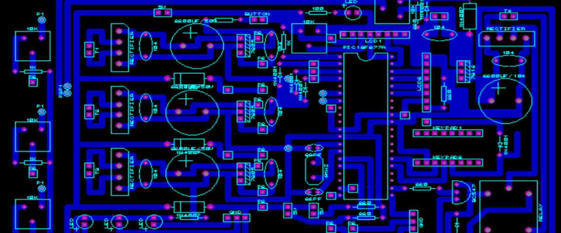
Layout

CSSP-BXFDN120 PCB design elements

Type of circuit: Analog

โ€ข Number of layers: 3 layers

โ€ข Pad stack sizes: 0.1×0.1mm

โ€ข Hole sizes: 0.3mm

โ€ข Copper thickness: 1.0mm

โ€ข Layer traces/spaces: 1.0/2.5mm

โ€ข Inter-layer traces/spaces: 2.0/-0.25/-0.

โ€ข Board width: 156mm

โ€ข Layer thickness: 0.02mm

โ€ข SMD pads/pins: 9.0×9.0mm

โ€ข Dip-Can holes: 3.0×2.5mm

โ€ข Number of LEDs: 2 x 0603

โ€ข Number of tactile switches: 3 x 5 x 4mm (bottom)

โ€ข Board thickness: 6.5mm (top)

โ€ข Operating voltage: 5 V

โ€ข Board height: 22mm (inputs)

โ€ข Box volume: 410ml (i.e. small box)

โ€ข External connections: USB port for programming and serial data, 2×0.1″ pin headers for breakout

โ€ข External power: minimum 0.5A, peak 0.

โ€ข Mounting holes: 2x13mm

Partitioning

Tones sounded by the instrument are divided into different octaves. This is because, to reproduce a tone, you must use a different number of synthesizer modules to generate that tone. It is important to note that this partitioning is only an idealized one. Many other factors like z-position and modulation levels affect how instruments. Examples include synths respond to notes played on the keyboard.

One significant advantage of using the QuickLogic ArcticLink III is its ability to create 16-bit audio files. It means it can take advantage of more than 8192 different frequencies in each tone.

This means that each of the sixteen synthesizer modules in the ArcticLink III can give way for a single oscillator with a frequency of 63.0kHz. It makes it possible to replicate the entire audible spectrum.

Another way to create complex feedback loops is through sound synthesis. This does not require an interface between the DSP and the musical instrument. You can set up several different tones to play simultaneously. Then you can use the resonance on one tone to modulate another tone. Some instruments, like old-school analog synthesizers, used this technique more than other instruments at their time.

Placement on the board

The ArcticLink III is small, but it is still quite a large PCB because there are many components on the board. The main parts of the board have only two layers, but only one side matters because they are placed on the board.

The central part of the board (the middle area) houses most of the processing power for synthesizing and editing sounds. There are eight audio processor modules here. Each module can take one tone from analog or digital input and translate that into a 16-bit waveform in memory. You can connect up to eight of these modules at once to create 128-voice polyphony simultaneously. In addition, each module has a sound synthesizer that we can program to make sounds of its own.

The eight input and output modules connect via two separate two-layer boards. They contain the universal data bus and the transconductance amplifiers.

The left half of the board houses seven square boxes that house the remaining processing power. These include oscillators, ring modulators, mixers, filters, and so forth. Each box also connects to its waveform memory. Unfortunately, each one is only 64 bytes in size (only 3.5 KB). However, this is sufficient for recording 256 waveforms at once, which might be more than enough for many purposes.

Routing

The ArcticLink III comes with a variety of connectors on the board. The most notable are two external USB headers. One which we can use to program the board and the other that we can use to connect an audio source via USB or CV/Gate. A serial data port also provides access to a serial device to program firmware updates and monitor sound parameters. There are also nine boards soldered onto the bottom side of the PCB, which make up six square “breakout” connectors. Each breakout contains either four QFN sockets for adding your hardware or four dip-can for prototyping projects.

The ArcticLink III includes a USB-to-Serial adapter (UART). It works similarly to the Adafruit Feather’s default USB-to-serial adapter.

There are two rows of input/output pins on the board, each with eight pins in each row. So, for example, the NanoKey should be connected to one row of those inputs and outs; UART and LEDs in the other.

Connections

The ArcticLink III connects with two headers attached to the bottom of the board. Each header has a USB-to-Serial adapter and a D-Sub connector for connecting to external audio sources, and a power pin. It comes in handy when you want to connect both the ArcticLink III and an external synthesizer at the same time.

There are four expansion connectors on the bottom side of the board: one for pushbuttons (usually under a rotary encoder) and three for LEDs. An audio output also allows you to connect your speakers or amplifier to the device.

A micro USB connection can connect it to a computer to program the board with different software.

Dip-Can sockets (2 x 0.1″ spacing)

The DSK comes with nine dip-can connections to interface with three tactile switches and a rotary encoder. Since the board itself only has three tactile switches, this makes it possible for you to add more switches if needed.

Power

The ArcticLink III uses a 3.3V power supply that we can purchase separately. In addition, you can use one of their DualUSB adapters, which provides both 5V power and USB connectivity to an attached device (such as an Arduino).

The power supply can connect the board: the 5V pin and the GND pin. The GND connector is preferable, as it will provide power to all the components at once. We also recommend connecting a decoupling capacitor (100ยตF) across the 5V and GND pins, as this helps prevent voltage spikes from causing trouble for any of the sensitive components on the board.

Power consumption on this board can vary greatly depending on what modules are on and what modules are currently working. However, the bare minimum that the board will consume is 16mA, which is the absolute minimum current required to power the USB-to-Serial converter.

It is recommended to use a power supply capable of pushing out at least 0.25A, but not too great than 0.5A, as this will prevent voltage drops on the 5V supply line. A separate 5V supply can be safely used to power the board without damage or malfunctioning of any chips.

When running a program that uses the serial port on the board, you should use an external USB-to-serial adapter. This is because the one on-board is unreliable and can affect data integrity if it makes mistakes. Ideally, Adafruit’s TTL-232 cable can be helpful with this project. It provides some 5V and 3.3V power to keep the ArcticLink III running while providing a reliable serial connection back to your computer via a USB port.

Clock Routing

We do clock routing by the pins on the UART 2 connector, connected to pins A3-A0 on the NanoKey.

Arduino vs. NanoKey

Both Arduino and NanoKey share the same number of pins (20). However, because it needs to provide 5V power and uses a USB connection, Arduino is more difficult to connect to the board. This means that if you want to use Arduino for programming or debugging, you will need a separate power supply for both options.

Physically, they are very similar in size. Both have an ATmega328P microcontroller with an 8MHz clock rate and 16MHz crystal oscillator.

Arduino has more available IO (interfacing pins): 40, 61, 62, 71, 72, 73 (VCC), 74 (RST), and 75-76 (IOREF). The NanoKey only has 39 lines: 18 for GPIOs 1 through 14 and GPIOs 15-22.

Since all of the NanoKey’s pins are used for general IO, and the Arduino doesn’t have any I/O specifically dedicated to controlling sound generation modules or other multimedia applications, it might be necessary to use a software serial library. The Adafruit_Serial library is an excellent example of one that could be helpful with input or output.

High-Speed Differential Pair

The ArcticLink III uses a high-speed differential pair connector to interface with the NanoKey’s I/O pins. This contrasts with the I/O scheme used by the Arduino, which uses a single differential pair to communicate with its attached modules.

The Arduino’s IO pins connect to general-purpose input/output pins, which means that we connect to any of your module’s inputs and outputs. However, that may not be what you want. For example, a high-speed differential pair connector considers differences in speed between lines and can use one line as a clock while another line is read or written.

When using a high-speed differential pair, your inputs and outputs must be well isolated from each other and anything else around them. When any current moves through a circuit, electricity tends to flow in all directions until it reaches an opening. If a ground pin connects to an input, it may draw a current, sending that current to the 5V input and potentially damaging your Arduino. The same goes for the opposite scenario.

NanoKey has 18 high-speed differential pairs in total: 8 on each side of the board. We can program each side separately. However, they will be treated as one big “mess” when it comes time to make a connection. Any high-speed differential pair can be either input or output connections at any time.

To maintain its full speed capability on the NanoKey, you need to isolate your inputs from any surrounding grounds that might draw current away from them.

Vias

The ArcticLink III both use vias to pass electricity from one side of the board to the other. This is important as it allows current to flow through all components while reducing voltage drops across any connections.

On most electronic circuit boards, you will find that vias are in between some or all of the pins on each side, which can limit the speed at which electronics can process data. In addition, a full-sized (4-layer) printed circuit board will generally split into smaller pieces for easier handling, which means that some areas won’t have a via in them.

The exact distance between vias may vary but should be at least 0.006″ or 1.27mm, the smallest distance that allows for the fastest signal propagation.

The NanoKey case has a limited number of vias because it uses a half-sized printed circuit board. Unfortunately, this means that some signal traces will be right next to each other, leading to signal degradation and even signal loss altogether if there is too much resistance or damping in between them.

For example, look at a close-up of the NanoKey’s differential pair connector:

This points out two issues in this area: it’s hard to see where the wires go between two rows of pins because they are very close together (0.25mm isn’t a lot). The other is that there are vias on both sides of this area, which can cause signal degradation.

Due to the limited space available between pins on the ArcticLink III, you will need to place vias very close to where you are connecting pins. In some cases, it might not be possible to have vias at all due to the design constraints on your design.

Isolations

The ArcticLink III requires high resistance to the board’s VCC pin (3.3V). A decoupling capacitor can provide this. It will help keep the voltage at 3.3V without causing problems for any other components on the board. This is generally not required. But, it can help ensure that no voltage spikes can cause trouble to any of the chips on the board while they are working.

A variety of different things can cause voltage spikes. One example is when you are programming the board with an external programmer, such as the FTDI basic breakout. This can cause voltage spikes that could harm the microcontroller or interfere with other components on the board.

Another way to cause a voltage spike is when an external power supply powers the board. Most external USB-to-5V converters have some way of limiting the output voltage or reducing it to something safe (such as 2.5 to 5 volts). If your board receives a voltage that it wasn’t expecting, this can damage the chips.

The best way to prevent these problems is to use a decoupling capacitor on the VCC pin on the ArcticLink III.

The exact value of this capacitor will vary depending on its placement on the board and how much current it is receiving from VCC and GND.

Electrostatic Discharge (ESD)

Electrostatic discharge (ESD) can cause damage to several different components. Some of these components may be in a position where they cannot protect themselves. For example, potentiometers and switches use conductive rubber or plastic not protected by the same system used to protect microcontrollers.

Electrostatic discharge can cause an object with a high electric potential to release that energy onto another object with a lower electric potential, which can permanently damage or destroy the electronics on your module. Therefore, it is essential to take precautions, such as using ESD-safe work practices or even purchasing an anti-static mat or wrist strap, so you don’t accidentally cause harm to your modules while developing them.

ArcticLink III CSSP-BXFDN120 applications Overview

The ArcticLink III chip is suitable for several different applications, such as:

Smart Textiles

ArcticLink III chips can be helpful with textiles to create smart clothing. This can include LED fabrics, shirts, gloves, and several other products. These products are generally low-voltage and high-current devices that need to be connected directly to the pins on the board.

For example, you could have a bright red shirt that turns green when you get close enough to something. To achieve this, you could connect a photoresistor R1 on one side of your shirt and R2 on the other side.

Home appliances

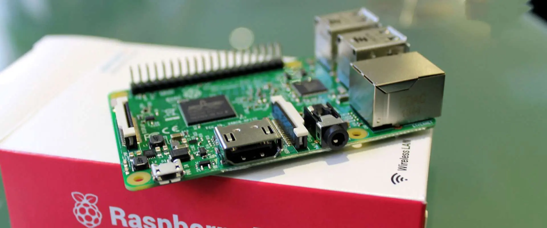
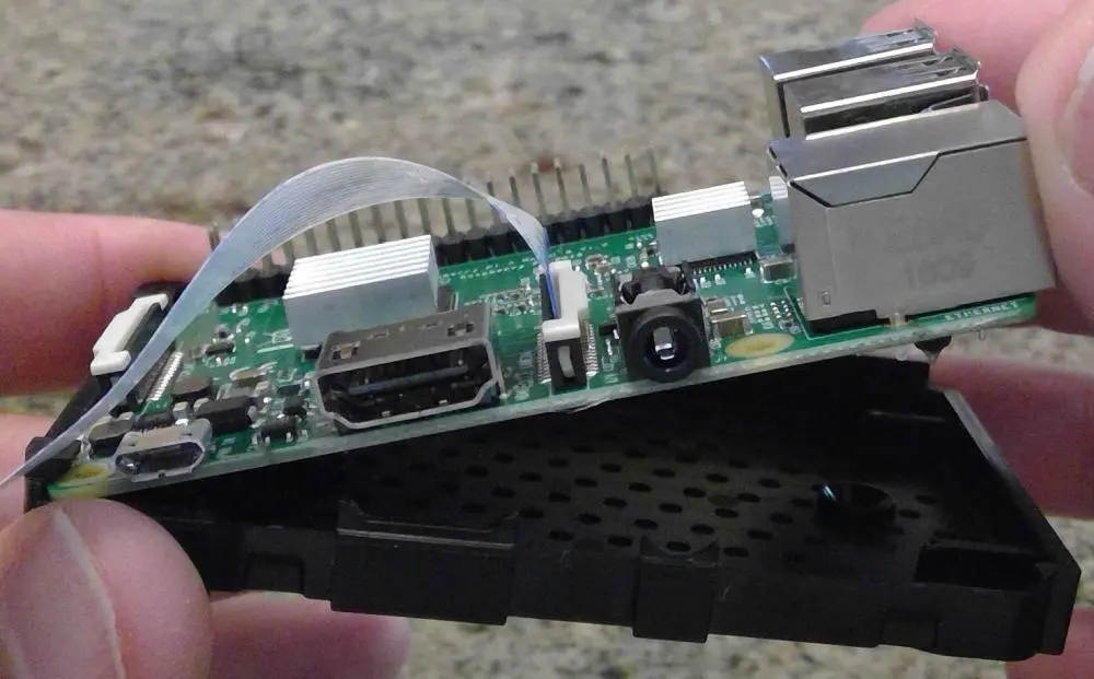
ArcticLink III chips can be helpful in intelligent thermostats, heating systems, and energy management systems. They often work with an external microcontroller that receives several inputs from sensors. They can also be helpful with the Raspberry Pi to add small computer-like features to devices that were not initially suitable for it, such as a small fan or light.

For example, you could have a device that controls -40 to +40 degrees Celsius in your house by receiving temperature readings and comparing them against a memory module. This would allow you to adjust the temperature at any time without having to worry about turning on or off the heater (or air conditioning).

Artificial Intelligence

ArcticLink III chips can create a small computer or even a smart home. This can include using the board to detect when someone is home, whether they are actually in the house, what they are doing, or if there are any activities in their bedroom.

As an example, you could have a board that detects your car and sends data back to you without having to set up anything: all you need to do is plug your car into the board and turn it on once, and it will automatically read how much gas there is in it.

5G Technology

ArcticLink III chips can be helpful in prototype devices part of the 5G network. They can also benefit devices that connect to a 5G network, such as smart TVs and cars.

This connection is often challenging to create, and the proprietary nature of 5G networks can make it harder to implement this kind of technology into your next project.

As an example, you could have a board that connects your smartphone with a TV or other peripherals without having any cables or wires between them. The phone could also automatically connect with any nearby devices on the same 5G network, which wouldn’t have been possible before.

Wireless Technology

ArcticLink III chips can be helpful in various wireless technology prototypes: including Wi-Fi, Bluetooth, and RFID. In addition, ArcticLink III can also help in other 3G, TD-LTE, or LTE-M technologies.

This technology is more widespread than 5G technology and requires less complex hardware to implement. This makes it easier for you to implement many different products that require communication between devices over the air. An example of this would be a board that would allow you to connect a smartphone with an external antenna so that it could communicate with your car over your garage door.

Internet of Things

ArcticLink III chips can be helpful in various prototypes that are part of the internet of things (IoT) system. These include “smart homes” and entertainment systems.

For example, you could have a board that detects when your car arrives home or is parked in the garage and sends this information to several services, such as Google Home or Amazon Echo.

The complexity involved with creating IoT devices can vary greatly depending on the type of product you are trying to build. As an example, you could do something as simple as putting an LED on top of a wireless switch so that you can control if your lights are on or off without having any wires between them.

Medical Equipment

ArcticLink III chips can be helpful with medical equipment to help create smart implants. They can also help connect other types of monitoring systems to the internet, such as blood pressure monitors or pulse oximeters.

Security and Monitoring

ArcticLink III chips can be helpful for home security alerts, anti-theft systems, and several different monitoring systems.

For example, you could have a board connected to your house’s water system and use an LED on top of it to show any water leaking from it (or if something is wrong) without checking it manually every time.

Conclusion

In conclusion, the QuickLogic ArcticLink III Family of chips is a versatile product that we can use in many different applications. For example, the ArcticLink III chip can be helpful with your Raspberry Pi to add small computer-like features to devices that were not originally suitable for it, such as a small fan or light.

How to Clean a Circuit Board ?

clean circuit board

Introduction

Circuit boards, also known as PCBs (printed circuit boards), form the backbone of most electronic devices. Over time, PCBs can accumulate dirt, grime, dust and other contaminants during manufacturing, storage, and use. Cleaning helps remove these contaminants to prevent issues like short circuits, corrosion, and impaired thermal performance. However, care must be taken not to damage sensitive board components while cleaning.

This comprehensive guide covers methods, materials, and best practices for safely and effectively cleaning circuit boards in electronics production, maintenance, and repair.

Reasons for Cleaning Circuit Boards

Cleaning PCBs provides both functional and aesthetic benefits:

  • Removes contaminants that may lead to shorts, false signals, and impaired connections
  • Helps dissipate heat efficiently by removing thermal insulators like dust and grime
  • Prevents arcing and leakage current issues in high voltage boards
  • Protects components and metal traces against corrosion
  • Improves conformal coating adhesion and appearance
  • Restores boards to visually clean condition for inspection
  • Removes residual fluxes after soldering to avoid further oxidation

Thorough cleaning should be standard procedure in PCB fabrication, rework, repair, and maintenance processes.

Safety Considerations for PCB Cleaning

Cleaning agents and methods can damage delicate board components if not done properly. Follow these safety guidelines:

  • Review board construction and identify sensitive components (MEMS, displays). Take extra care near them.
  • Avoid cleaning agents that can damage component materials and metallic traces. Match cleaning solutions carefully.
  • Use anti-static safety gear to avoid electrostatic discharge (ESD) through components.
  • Allow sufficient drying time before reconnecting power to avoid short circuits.
  • Follow directions for proper usage and handling of commercial cleaning agents like solvents.

Working safely prevents introducing new issues like ESD damage, chemical corrosion, and residual moisture while cleaning boards.

Dry Cleaning Methods for PCBs

PCB Cleaning
PCB Cleaning

Dry cleaning techniques avoid using liquids for removing contaminants:

Vacuuming

Vacuuming is an easy dry method for removing loose dust and dirt from PCB assemblies.

Procedure:

  • Use an ESD-safe vacuum with a brush nozzle attachment
  • Vacuum across exposed surfaces of the board, focusing on high buildup areas
  • Angle the brush to dislodge stubborn contaminants
  • Check areas under large components and sockets

Pros:

  • Fast, gentle, and efficient for removing loose particulate debris
  • Mobile vacuums allow cleaning mounted boards

Cons:

  • Ineffective for sticky oils/greases or removing corrosion

Air Duster Spray

Pressurized air cans release high pressure gas that can dislodge contaminants.

Procedure:

  • Hold can 6-8 inches from board surface
  • Blast short bursts across and under components, connectors etc.
  • Wipe away dislodged particles with lint-free cloth

Pros:

  • Quickly removes dust and surface debris
  • Reaches narrow spaces under components

Cons:

  • Does not remove stuck-on contaminants
  • Air blast can damage fragile parts if not careful

Lens Brush

Soft, flexible lens cleaning brushes can remove contaminants from hard-to-reach spots.

Procedure:

  • Use light pressure and brush across board surface
  • Reach into tight spaces between board parts
  • Fold brush tip to expose fresh bristles

Pros:

  • Versatile for meticulous dry cleaning of delicate areas
  • Compact and portable

Cons:

  • Time consuming for large boards
  • Cannot remove strongly adhered contaminants

Dry cleaning works well for removing loose dust, dirt and small particulate matter from circuit boards.

Wet Cleaning Methods for PCBs

No-Clean Flux vs. Water Soluble Flux

Wet cleaning methods use solutions to dissolve and displace stuck-on contaminants:

Isopropyl Alcohol (IPA)

IPA is a mild organic solvent commonly used for PCB cleaning.

Procedure:

  • Soak lint-free cloth or swabs in 99% pure IPA
  • Wipe across board surface, applying moderate pressure on stained areas
  • Allow to air dry fully before reconnecting power

Pros:

  • Removes light oils, fluxes, thermal paste from boards
  • Evaporates quickly without residue
  • Low cost and easily available

Cons:

  • May not remove heavy grease or corrosion
  • Can damage rubbers, plastics if left too long

Cleaning Pens

Pens containing IPA or other cleaning solutions allow spot cleaning deposits.

Procedure:

  • Shake pen to saturate nib with cleaning solution
  • Rub nib gently over contamination area
  • Let ink dissolve deposit for 10-30 seconds
  • Wipe away contamination with nib

Pros:

  • Allows precision cleaning of specific spots
  • Easy to carry for field use

Cons:

  • Takes effort to clear heavy buildup
  • May leave traces of cleaning solution residue

Ultrasonic Cleaner

Ultrasonic energy helps dislodge dried contaminants from boards.

Procedure:

  • Fill tank with suitable cleaning solvent like IPA, water, or detergent
  • Immerse board and energize ultrasonic transducer
  • Run for 5-10 minutes allowing cavitation to remove contaminants
  • Rinse board with clean solvent after ultrasonic cleaning

Pros:

  • Very effective for removing old, dried contamination
  • Able to penetrate tight spaces and component undersides
  • Does not require rubbing or scrubbing

Cons:

  • Requires an ultrasonic system with solvent tank
  • Care needed to avoid component detachment

Wet cleaning processes help clear more stubborn, adhered on grime, oils and fluxes from PCBs.

Cleaning Agents for PCBs

How to solder the chip components-Cleaning Solder Resist

Choosing the right cleaning solution ensures effective contaminant removal without damaging boards:

  • Isopropyl alcohol (IPA) โ€“ General purpose cleaner suitable for light oils and fluxes
  • Acetone โ€“ Stronger than IPA but can damage component plastics
  • Cleaning solvents โ€“ Proprietary blends optimized for PCB cleaning applications
  • Water โ€“ Inexpensive but leaves conductive residues requiring thorough drying
  • Detergents โ€“ Used as safer aqueous cleaners combined with water
  • Ozone-based cleaners โ€“ Effective cleaners made from ozone gas in water

Factors like cost, safety, component compatibility and waste disposal guide the selection of PCB cleaning agents.

Cleaning Different PCB Assemblies

PCB cleaning methods may vary by board type and assembly:

Bare Boards

  • New blank PCBs – Use IPA rub to remove manufacturing residues
  • Reworked boards โ€“ Clean light corrosion; degrease if thermal paste was used

Coated Boards

  • Avoid coating damage from rubbing. Soak swab in IPA and lightly wipe.

Conformal Coated Boards

  • Gently wipe with solvent like acetone before recoating to improve adhesion

Assembled Boards

  • Vacuum loose dust. Use air duster on components. Exercise caution.
  • Swab clean between components with lens brush and IPA-soaked tips
  • For heavy buildup, partial disassembly may be required for access

Assess PCB components and type before selecting suitable cleaning method.

PCB Cleaning Process

Follow a systematic approach for consistent cleaning results:

1. Dry Pre-cleaning โ€“ Use vacuum, brush and air spray for loose contaminants.

2. Wet Cleaning โ€“ Apply preferred solvent like IPA and wipe board. Allow to dry.

3. Rinsing โ€“ Use fresh solvent to remove any remaining cleaning agent residues.

4. Drying โ€“ Allow board to dry fully before reassembly and testing.

5. Final wipedown โ€“ Wipe with lint-free cloth to remove any remaining lint, fibers or dust.

6. Visual inspection โ€“ Inspect under bright light for cleanliness before reassembly.

Establishing a repeatable process helps achieve contaminant-free PCBs.

Cleaning Tips for PCB Maintenance

Some best practices for cleaning during PCB maintenance and repair:

  • Assess buildup and select suitable cleaning method โ€“ solvent wipe for light oils or ultrasonic bath for heavy residue.
  • Take photos before disassembly as a guide for correct reassembly.
  • Use anti-static safety gear to prevent ESD damage which may look like new contamination.
  • For coated boards, clean only affected areas to minimize coating wear.
  • Rinse with fresh solvent after wet cleaning and allow longer drying time for densely populated boards.
  • Visually inspect under bright light or microscope after cleaning to check for residue.
  • Properly store cleaned boards in anti-static bags before system reassembly.

Meticulous cleaning as part of regular maintenance keeps PCBs contaminant-free for reliable performance.

Conclusion

clean circuit board

Cleaning is an important process for removing potentially harmful PCB contaminants like grime, dusts, oils and fluxes. Dry cleaning techniques like vacuuming, air spray and lens brushing remove loose particulate matter. For clearing heavier residue, wet cleaning with solutions like isopropyl alcohol is more effective. With the right process and cleaning agents, even old stubborn contamination on boards can be cleared without component damage for restored board performance.

Frequently Asked Questions about Cleaning Circuit Boards

Here are some common questions about PCB cleaning:

Q: What are some must-have supplies for cleaning PCBs?

A: Useful supplies are high purity isopropyl alcohol, cleaning swabs, lens brushes, low-pressure air duster, ESD-safe mat, lint-free wipes, magnifying glass.

Q: How often should PCB maintenance cleaning be done?

A: For normal environments, annual cleaning suffices. In harsh industrial conditions with more contaminant exposure, cleaning every 6 months is recommended.

Q: Is tap water or soapy water OK for PCB cleaning?

A: Avoid tap water due to mineral residues. Small amounts of mild detergent in deionized water can aid aqueous cleaning.

Q: Which cleans better – acetone or isopropyl alcohol?

A: Acetone is a stronger solvent so it can remove some stubborn contaminants that IPA cannot. However, acetone can damage component plastics.

Q: Is ultrasonic cleaning safe for all PCBs?

A: Ultrasonic cleaning is very effective but high ultrasonic vibrations can damage fragile components in some boards.

What is .CAM File?

.CAM File

Mostly, .cam files belong to Autodeskโ€™s Eagle. The extension of the CAM filename has to do with the files that are created using the Drawing Editor. This is then saved in the FastCAM format.

Furthermore, these CAM filesโ€™ contents may deal with an objectโ€™s material, thickness, quantity, and path. Also, the extension of the CAM filename has to do with designs of printed circuit boards (PCB), which are saved in the vector graphics format of Gerber. The creation of these types of PCB designs may have happened with programs like CircuitCAM or Eagle.

Also, HouseCall, which is known as an anti-malware program, helps by using the CAM file as a place to save the backup of the AUTOEXEC.BAT file.

Furthermore, CimaGraphi, which is a CAD/CAM design software that saves some of the CAD data in the CAM files. Also, the projects which were created with Camtasia Studioโ€™s older versions also make use of the extension of the CAM filename. Note that Camtasia Studio is a video editing and screen recording software.

Also present in the CAM project file is an ongoing work, which is going through editing. For example, the video game – Age of Wonders III makes use of CAM files in storing campaign maps. Furthermore, the extension of the CAD filename are pictures that are also captured using the digital cameras of CASIO QV.

How do I Open .CAM files?

To open CAM files, you will need reliable and suitable software such as Eagle. Without using a proper software, a message from Windows will pop up like โ€œhow do you wish to open the file.โ€ You may see another message like โ€œWindows doesnโ€™t recognize or cannot open the fileโ€. Another thing you may see is a similar Android/iPhone/Mac alert.

One you fail to open the .cam file the right way, try to long-press that file, or right-click it. Next, select โ€œOpen withโ€ and then tap on any application you want.

What Programs Can I Use to Convert and Open .CAM Files?

You may be searching for programs that you can use in converting and opening .cam files. Here are some of them.

Eagle

This is by Autodesk. Here, the .cam files are seen as Eagle cads. This is because this file type is mainly used or created with the help of this software.

Altium Designer

This one is by Altium, and it is a combination of computer-aided design and manufacturing tools that helps in the design, the printing, as well as the exporting of PCBs. Also, the reading of the design components of CAM PCB which gets into the Altium Designer is only possible by the Editor component of CAMtastic. Also, the file format is under the category called CAD.

Abeโ€™s Oddysee

This is a computer video game in 2D form. Here, Abe, which is the major character of the game is a meek slave that works in a factory for meat processing. However, Abe decided to find a way of escape after discovering that he and everyone related to him would be slaughtered.

Furthermore, the storing of this gameโ€™s background is in the .cam files. The format of this file is placed under the โ€œGameโ€ category.

CimaGraphi

This is by GraphiTech. It is a reliable CAD/CAM program that works for different 3D and 2D applications like milling and engraving. Also, the storing of some of the milling data that are utilized by CimaGraphi is done in CAM files. Also, the format for the file is under the CAD category.

 Camtasia Studio

This is by TechSmith. This project is a video editing or screen recorder software, which helps in the creation of training materials and demos. The storing of the programโ€™s older versions is usually in the .cam files. The format for this file is under the CAD category.

HouseCall

This is a program by Trend Micro, and it is useful in protecting computers against spyware, malware, as well as other possible cyber threats. Furthermore, the saving of the backup of the AUTOEXEC.BAT file of HouseCall is in the CAM file. The format of this file is under the Backup category.

Drawing Editor

This is by FastCAM. For the Drawing Editor, we can say that it is a software for product fabrication. This helps in the creation and the cutting of the designs of product parts from the geometric shapes, which are accurately drawn.

The creation of objects using the Drawing Editor is taken to the CAM files for storage. The file format is under the CAD category.

PhotoModeler

This is a software, which allows the user to create great and accurate 3D and 2D models as well as measurements from the photographs taken using a very standard camera. Also, One PhotoModeler calibrates the camera, it goes ahead to save the details of the camera in the CAM file. The file format is under the category โ€œDataโ€.

QV

This is by Casio. These are Casio digital cameras that are no longer in production. The photographs taken with the help of these cameras are stored in the files having the CAM filename. The file format is under the Raster Image category.

NASCAR Racing 2002

This one is by Sierra. This is a video game that involves car racing. This features real tracks for race. The storage of the replay settings of this gameโ€™s camera is in the .cam file. The file format is under the Game category.

How Do You Solve Problems Involving CAM Files?

First of all, you will need to associate the extension of the CAM file with the right application. Visit Windows, then check any CAM file, and right click it. Next, click โ€œOpen Withโ€ then tap โ€œChoose another appโ€. After this, choose another program, then go ahead to check this box saying โ€œAlways utilize this app to help open all *.cam filesโ€.

Next, update the software which you use in opening your PCB designs. This is because only the latest version allows the use of the latest format of .cam file.

To ensure there is no virus infection or corruption on your .cam file, get this file again and do some scanning using the virustotal.com of Google.

Conclusion

By now, you should have a clear understanding of what .cam file is all about. If you have any more questions, feel free to contact us.

What is .PCB File ?

.pcb file

Technology keeps advancing as the world changes. So is the PCB industry. The sketching of traces and traditional methods of etching get obsolete in the PCB industry. The computer has changed a lot in the technology world. Almost all fields of technology have been impacted positively. However, computer technology makes the art of designing electronic boards that takes less space and houses some electronic components possible.

There are several software that can design a printed circuit board. CAD and Altium are a good example of such. A PCB file is very important for a PCB design. Without it, manufacturing canโ€™t take place. A PCB file is important to design and build a satisfying board. This article discusses every important detail on a PCB file.

.PCB File โ€“ What is it?

A PCB file is a document that comprises necessary information on PCB layers. Also, it contains information related to a circuit board. In this document, you can find details of bottom and top silkscreens. A PCB file features several information needed for PCB design and manufacturing. Also, these files can be in a binary format.

PCB files help to design the layouts used for printing the physical board. These files help PCB manufacturers to design these layouts.  Engineers offer PCB files when placing a PCBA order. The Gerber file is one of the most accurate and common files. Also, the Eagle file and .PCBDOC are accurate files. These files are ideal for the manufacturing and testing of a circuit board.

How do you Open a .PCB file

A .PCB file is very easy to open if you follow the necessary steps. You will need a software such as Altium Designer to open a PCB file. If your file doesnโ€™t open, long-press or right-click the file. Also, you need to launch the .PCB file on your computer. If you have the right file associations, your .PCB file will be opened.

Programs that can open and convert .PCB file

There are several programs that can open and convert your.PCB files. These programs include:

CADSTAR

This is a Windows based desktop PCB design solution by Zuken. It is easily integrated in your design environment. A .PCB file features the layout for printing the circuit board.

Altium Designer

PCB files are also known as Altium Designer cads. This is because they are primarily designed or utilized by Altium limited.

PowerPoint

This is a computer presentation program. Also, PowerPoint can display data in an eye-catching slide. This program was initially released for Mac OS machines. However, any modern operating system supports this program. Also, the .PCB file features the application settings data.

Winboard

This is a PCB design software designed in the early 2000s. It is the first program for independent PCB design and manufacturing.  However, there is limited documentation as regards how the manufacturer uses the PCB file. Winboard is a CAD.

PADS

This is PCB design software that offers a personal automated design system. Also, this system meets the userโ€™s needs to ensure effective and fast PCB design. PADS is a popular PCB design software. Also, it comprises the layout used for printing the physical board.

PCB Artist

PCB Artist is a PCB design file created by Advanced Circuits. It is one of the most efficient PCB layout software. However, this software is different from others. Also, it is entirely free. However, it canโ€™t output a GRB file for general purposes. PCB Artist features the layout used for printing the circuit board.

Print Shop

This is user-friendly desktop publishing software by Broderbund Software. Print Shop features thousands of photos and many desktop publishing tools. Also, it comprises pre-designed project templates. This file format is specifically classified as Page Layout.

The Benefits of PCB Files to Gerber File

Some engineers try to convert .PCB files into Gerber files. However, the majority of electronic engineers wonโ€™t convert a .PCB file into Gerber file and drilling data before submitting it to the factory. They would rather export the PCB file from the software and send it to the PCB manufacturers directly.

You may not need the Gerber file your PCB manufacturer converted. This is because PCB engineers and electronic engineers understand PCB differently. Also, if the parameter of the components in the PCB file is defined during the design, you donโ€™t want to see them on the PCB.

The Gerber file features two formats RD-274-X and RS-274-D. The RS-274-X is the extended Gerber format that comprises D code information. Also, the RD-274-D is the basic Gerber format accompanied by a D code file.

Why is a .PCB File Needed?

A .PCB file is a document crucial for the manufacturing and design of a circuit board.  A. PCB file helps to create the layout for printing a circuit board. Also, PCB manufacturing canโ€™t be successful without a .PCB file. PCB files comprise installation of components. Also, they offer an illustration of the connected relationship of each part to design a board.

Files Needed for a PCB Assembly

Documentation is an important part of a PCB assembly. It helps to realize a high-quality board. Also, designers need to be careful of recording the right information. The design process might be complicated. Therefore, these files are necessary for PCB manufacturing.

PCB file

This is one of the most important files a PCB manufacturer needs to build their final product. It contains information like layers, dimensions, and drill guides.

BOM

Also, known as the Bill of Materials, BOM comprises standard default information. This information includes manufacturer part number and reference silkscreen. Without a detailed BOM, manufacturing canโ€™t occur. This file helps to evaluate the accuracy of your final product.

Gerber file

This file is as important as your PCB board. It is a set of files that creates several layers of the PCB. Every layer requires a different Gerber image file.

NC Drill file

This functions as a secondary file you need to send to the PCB manufacturer alongside the Gerber file. The NC Drill file determines the size and position of the drill holes on the PCB.

Conclusion

The importance of the .PCB file canโ€™t be underestimated in the PCB industry. Therefore, this article has provided the necessary information about the .PCB file.

What is NC Drill File?

NC Drill File

Generating the NC Drill Files Based on Different Softwares for PCB Design

Printed circuit boards form the backbones of all electronic equipment and devices. There has been a rise in the circuit’s density and the reducing size trends of the electronic products. This has caused circuit boards to transform into a higher complexity.

Vias or holes, which serve as electrical connections forming between the layers and the corresponding functions that a board will use according to the requirements of the design will not work effectively unless you design or manufacture them suitably.

For any unsuitable manufacturing, you can solve it easily. This is by choosing a top PCB manufacturer for unsuitable design. Also, the solution majorly depends on the engineers who have designed the circuit board. They must create a reliable design file with respect to what the fabricators of the PCB does during manufacturing.

It is a general belief that the generation of the NC drill file has been an issue for most engineers of PCB design. This is why it is necessary to summarize the guidelines of the design board on the software for your PCB design.

What is NC Drill File?

gerber and drill files

NC Drill File is also known as numeric control drill file. This indicates a file that regulates all the information relating to via or hole drilling requirements. These include hole location and size, and tooling size.

It is very necessary for engineers of PCB design to create the NC drill files. This is because you can avoid so much trouble by converting the PCB files into Gerber files or NC drill files.

However, the truth is that some engineers end up sending the PCB files to the PCB manufacturer directly. They fail to convert into Gerber files or NC drill files.

The usual workflow is this. After receiving the files of the PCB design, the board fabricators will have to go ahead and convert them into NC drill files. Then can they continue with the manufacturing. This is because the electronic engineers that work in the PCB fabrication house have a different understanding of PCBs from that of PCB engineers. It is possible that the Gerber file isnโ€™t what the pcb designer was expecting.

Furthermore, during the generation of the Gerber files, some indefinite aspects or issues may result. This is due to differentiations in software version. The best solution is, engineers of the PCB design will have to convert these design files to Gerber files. The NC drill files will also be created, which will all be sent to the PCB manufacturers.

What Does the NC Drill File Format Look Like?

You can generate NC Drill files by using almost all the softwares for PCB design with Excellon as its usual or ordinary format. Excellon was initially a CNC system manufacturer for routers and drillers.

Due to its active role as well as long life in PCB routing and drilling equipment, there is an acceptance and coining of Excellon as some industry standards.

Read more about:

Generating NC Drill File Using Altium Designer

Checking Altium Designerโ€™s main interface, click file, then fabrication outputs, after then, click NC Drill files. Next, go to the dialogue of the NC Drill setup, where you have to specify some options, which include the NC Drill Format, Coordinate positions, Trailing/leading zeros, etc.

Data units in NC Drill Files could be either millimeters or inches, which should work with those of the Gerber files. As regards the format, there are three major sections present. These include 2:5, 2:4, and 2:3. Here 2:3 shows the least resolution. The 2:5 shows the greatest resolution.

Furthermore, before you go ahead to make a decision regarding the format, it is very important to reach out to the contract manufacturer of the printed circuit board in order to ascertain which of the format works with their level of manufacturing.

With zero suppression, the NC Drill files are driven to be neat and fit and it relies on the application, convenience, and hosts of the PCB designers.

When you suppress leading zeros, the starting zeros will end up being removed. So also, when you pick suppress trailing zeros, then the ending zeros will become removed.

There are two alternatives for coordinate positions. These include relative origin and absolute origin. You should choose any of these according to the specific requirement of the pcb designer. However, it has to be exactly the same as the coordinate positions, which are regulated in the Gerber files.

You can pick other items, if they are necessary for the projects. Once all the items have been determined, just press OK. This generates all the NC Drill files that will be stored into the subfolders default path under the folder that contains the project file.

Generating NC Drill File By Using OrCAD (Cadence Allegro)

This is different from the Altium Designer. The NC Drill Filesโ€™ default format that Cadence Allegro exports, is not for Excellon. So, before generating the NC Drill Files for real, it is important to set certain parameters. All you have to do is to click Manufacture, then NC, then NC Parameters. This will help you gain entrance into the NC Parameters dialogue.

In this dialogue, thereโ€™s a need to determine the items of Excellon format and Output file. Concerning the Code in the Output file, generally, it is acceptable to pick the ASCII. This is because it is a much newer code type in contrast to EIA.

In order to create an NC Drill File using Excellonโ€™s format, it is important that you click before the Enhanced format of Excellon. To achieve zero suppression, make sure that you click before Trailing or Leading zero suppression with respect to the demands or project needs of the PCB designer or just to conform to the Gerber Files.

Furthermore, after the determination of the items, click the Close button. This will allow the NC Parameters dialogue to escape. After determining the items present in the dialogue, tap Drill. This will end up the generation of the Drill Files generation.

Conclusion

In this article, we have been able to explain ways of generating the NC Drill Files based on different softwares for PCB design. Please message us if you have any questions.

What does the flame sensor do?

flame sensor

Introduction

A flame sensor, also known as a flame detector, is a sensor designed to detect and respond to the presence of a flame or fire. It serves as a critical safety and control component across many industrial and residential applications that use a flame, allowing system activation or emergency shutdown if unsafe conditions are sensed.

This article provides a comprehensive overview of flame sensor working principles, types, applications, selection factors, installation considerations, and usage in modern safety control systems.

Flame Sensor Working Principles

Flame sensors operate on different physical principles to detect the light, heat or combustion products from a flame and provide a corresponding electrical signal. Here are the main detection methods used:

Ultraviolet (UV) Flame Detection

Flames emit light in the ultraviolet spectrum which is invisible. A UV flame detector senses this UV radiation:

  • Sensor contains a UV sensitive photocell to convert UV into electric current
  • UV is focused onto the photocell using a lens and filter
  • Output current indicates strength of UV, signaling a flame
  • False triggers avoided by ignoring visible/IR

Provides fast response and high sensitivity but can be affected by arc welding and sunlight.

Infrared (IR) Flame Detection

Flames emit wideband infrared radiation. An IR flame sensor measures IR:

  • Contains an IR sensitive photodiode or pyroelectric cell
  • Optical bandpass filter passes IR radiation to the sensor
  • Variable electric signal indicates the IR intensity
  • Fast reacting and low cost but may false trigger on hot objects

Ultraviolet/Infrared (UV/IR) Dual Sensing

Combines UV and IR sensors:

  • Independent UV and IR sensing channels
  • Outputs combined through logic circuits
  • Triggers only when both UV and IR detected
  • Avoid false triggers from individual sources
  • More expensive but robust detection

Flame Ionization Detection

Uses two electrodes to detect ions generated by a hydrocarbon flame:

  • Voltage applied across two metal electrodes in the flame path
  • Flame combustion produces ions causing current flow
  • Higher current indicates greater ionization from larger flame
  • Very fast response to flame initiation

Prone to contamination and saturation effects.

Thermopile Infrared Sensing

Thermopile sensor measures infrared heat emitted by the flame:

  • Multiple thermocouple junctions convert IR into voltage
  • Changes in flame heat alter the output voltage
  • No spectral filters needed, detects all IR wavelengths
  • Withstands high temperatures, resistant to corrosion

Slow response time and lower range. Mainly used for fire detection.

Flame Rectification

Uses flame’s ability to conduct alternating current to detect combustion:

  • Sensor consists of two isolated probes in flame
  • AC voltage applied; current flows due to flame conduction
  • Higher current indicates larger flame
  • Quick responding and simple

Effective only for open flames and certain contaminants can affect readings.

Flame Sensor Types

flame sensor

Flame sensors are made in different forms suited for specific flame monitoring applications:

Infrared (IR) Point Flame Detectors

  • Contain IR sensor aimed at a specific point in field of view
  • Used to monitor flames in furnaces, boilers, gas trains
  • Low cost, compact size but narrow monitoring area

Ultraviolet (UV) Point Flame Detectors

  • Monitor a point flame source in UV spectrum
  • High sensitivity with fast response time
  • Applied in aircraft engine exhaust, industrial furnaces

UV/IR Point Flame Detectors

  • Combination IR and UV sensors
  • Look at a specific flame point
  • Avoid false triggering from environment
  • More expensive than IR or UV only

Infrared Line-of-Sight Flame Monitors

  • IR sensor with linear field of view
  • Detects flame anywhere along a line path
  • Used to monitor large fuel storage tanks
  • Cover wide areas from a single location

Flame Imaging Flame Detectors

  • Contain multi-element IR sensors for flame spatial imaging
  • Analyze flame image patterns to verify true flames
  • Advanced false alarm immunity
  • High cost limits major installations

Flame Scanners

  • IR sensor scanned across coverage area using mirrors
  • Sequentially monitor large angular regions
  • No blind spots with complete coverage
  • Complex mechanical construction

Applications of Flame Sensors

Flame sensors serve as a critical protection and control component in the following applications:

Industrial Furnaces and Boilers

  • Monitor main burner flames
  • Shut off fuel on flame failure to prevent unsafe accumulation

Gas Turbines in Power Plants

  • Monitor combustion zone
  • Improve efficiency by optimizing fuel-air ratio

Aircraft Engines

  • Monitor jet engine exhaust flames
  • Feedback for engine performance control

Fuel Storage Areas

  • Detect leaks and fires in refineries, tank farms
  • Emergency isolation of unsafe tanks

Chemical Processing Plants

  • Monitor flames in crackers and reformers
  • Prevent explosive conditions by shutting down fuel

Flare stacks

  • Monitor presence and stability of waste gas flares
  • Indicates proper combusting of hazardous gases

Vehicle Engines

  • Monitor fuel combustion as part of engine management systems
  • Provide feedback for optimum fuel efficiency

Fire and Smoke Detection Systems

  • Detect fires and trigger suppression systems
  • Close fire dampers in HVAC systems on smoke

Burner Management Systems

  • Perform pre-ignition safety checks
  • Monitor steady flame during operation
  • Timely fuel cutoff on flameout

Residential and Commercial Furnaces

  • Monitor pilot and main burner flames
  • Prevent gas buildup on flame failures

Flame Sensor Selection Factors

Key considerations when selecting a flame sensor:

  • Application โ€“ The flame type, fuel source, monitoring needs and environment guides selection.
  • Detection method โ€“ Type that matches flame emission characteristics. IR best for general purpose.
  • Sensitivity โ€“ Minimum flame intensity required for reliable detection.
  • Response time โ€“ How fast it detects flame initiation or loss. Under 10 sec ideal.
  • Detection range โ€“Distance and angle from which it can monitor flames.
  • False alarm resistance โ€“ Immunity to normal ambient variations that may falsely trigger.
  • Operating temperature โ€“ Must withstand temperatures in monitored area.
  • Approvals โ€“ Certified sensors satisfy legal and insurance requirements.
  • Output โ€“ Digital, analog, fieldbus output options for interfaces.
  • Diagnostics โ€“ Internal self-checks for sensor health reporting.
  • Mechanical design โ€“ Housing, viewing angle, mounting provision etc.
  • Cost โ€“ Higher detection performance costs more.

Proper flame sensor selection provides reliable detection and avoids nuisance shutdowns.

Flame Sensor Installation Tips

Optimal mounting location is necessary for proper flame sensor operation:

  • Install in the combustion chamber for hottest view and quickest response to flame loss.
  • For large furnaces, install multiple sensors to monitor primary and secondary combustion zones.
  • Must have unobstructed line-of-sight of flame being monitored.
  • Mount at an angle to allow any accumulated material to drain off instead of blocking view.
  • Keep clean by avoiding areas with soot buildup or material condensation.
  • Seal housing for harsh environments but allow ventilation to prevent internal fogging.
  • Use fixed rigid conduit for wiring as vibration can break connections.
  • Follow manufacturer’s guidelines on proper wiring, grounding and separation from electrical noise sources.

Proper installation position is key for reliable flame strength monitoring and loss detection.

Integrating Flame Sensors in Control Systems

Flame sensors serve as a critical component in burner management and fire protection systems:

Burner Control

  • Performs pre-ignition safety checks to allow fuel flow
  • Monitors pilot and main flame during firing
  • Triggers safety shutdown sequence on flameout

Fire Detection and Suppression

  • Detects fires and triggers alarms, suppression systems
  • Closes fire dampers in ventilation systems
  • Shuts off fuel lines to stop fuel supply to fire

Advanced automation systems integrate array of flame detectors with analytics software for large area monitoring.

Conclusion

Flame sensing is a crucial technique for combustion safety and efficiency in critical processes across industry and infrastructure. Flame sensor selection requires matching detection mechanism with the specific flame and environment characteristics. Proper sensor integration during initial design stages along with correct mounting placement enables reliable flame condition monitoring and emergency response. With robust flame detection technology ensuring safe operating conditions, process industries can reap the benefits of combustion and fuels without the associated hazards.

Frequently Asked Questions about Flame Sensors

Here are some common questions regarding flame sensors and their usage:

Q: How does a flame sensor detect fire?

A: It uses spectral, spatial or conductive properties of flames to sense UV radiation, infrared light, heat or ionized gases and signal a flame condition.

Q: What industries commonly use flame sensors?

A: Power generation, oil and gas, chemicals, aviation, furnace manufacturing, building infrastructure rely on flame sensors.

Q: What sensors offer the highest flame detection performance?

A: Flame detectors combining both ultraviolet and infrared sensing in one housing generally provide the highest detection sensitivity and fastest response with minimal false triggers.

Q: What is the typical detection range of flame detectors?

A: Point flame detectors have a range around 3-6 meters. Line-of-sight models can monitor fires up to 60 meters away. Imaging flame detectors operate up to 45 meters.

Q: How often should flame sensors be maintained?

A: Annual inspection and cleaning is recommended. Harsh environments with soot or salt deposition may require cleaning every 3 months.

What is .gbr file

.GBR File

Files having its extension as a .GBR file may likely be a Gerber file. This Gerber file helps in storing the designs of printed circuit boards. The majority of programs for PCB design have the ability to export the data to any Gerber file.

However, if it is different from a Gerber file, then your own could be the GIMP Brush file. This file is useful for the editing software for GIMP. This file type holds images, which the program utilizes in painting any repeated strokes to the canvas.

The extension .gbr file also has another use. This is for the Ruleset files of the Game Boy. This can be integrated into the standard as well as super type of Game boy. It is also useful in Game Boy Color.

How do I Open a .GBR File?

You can achieve this using different programs, which are mostly free. Some of these programs offering free service include Gerbv, PentaLogix ViewMate, and GraphicCode GV-Prevue. A few of these programs support the viewing and printing of the measurements. Another option for you to use in opening the Gerber file is to use the Altium Designer. However, this isn’t free

You can also view .gbr files online. Ucamco, who are the format’s makers, features the Reference Gerber Viewer, which is free. This allows you to make an online upload of the file. By doing so, you will easily view it using your browser.

The Brush files of GIMP are utilized with GIMP. This functions effectively on macOS, Windows, and Linux. Also, if the .GBR file takes the Tileset format of the Game Boy, then you can use the Game Boy Tile Designer to open the file

Converting a GBR File: What you should do

Before you convert the .gbr file, you must know the type of format that it is. This is very necessary because it will help you decide which of the converter programs you should make use of since all three formats mentioned above work and function independently of each other. What this means is that you cannot convert just any file into the .gbr file format. This can never work.

Concerning the conversion of Gerber files, there’s a possibility that some of these programs above will not just open it, but save the .gbr file into a brand new format. However, if this isn’t the case, the Gerber files can be converted using GerbViee to SVG, TIFF, DWG, PDF, DXF, as well as other formats.

Furthermore, using an online viewer like Online Gerber Viewer may work as well for saving your GBR file into the format of the PNG image.

Also, you can use FlatCAM to convert your Gerber file into G-code. Another you can try us Cenon, that’s if the other converters fail to work.

In order to save the GIMP file to the ABR so as to use it in Adobe Photoshop, then there’s a need to convert it first to PNG using a program such as XnView.

Next, open this PNG file in your Photoshop and then select what part or section of the image must be transformed to a brush. You can make this brush via Edit, then choose the Define preset menu.

The Tileset files of Game Boy can be converted into other types of file formats using the Tile Designer Program for Game Boy. It allows you to save GBR to OBJ, S, BIN, C, and Z80, via the file then export to the menu item.

What to do if you still cannot open the file

If you still cannot open the file, check that file extension again. It is possible that if none of the programs work then you are probably misreading that file extension.

Furthermore, this is significant because at times some file formats may share very similar extension letters, but that doesn’t mean that they are related in any way or you can use the same tools to open them.

GBR files for instance feature all the three similar letters for the file extension. However, they are files of the GRIB Meteorological Data which are saved in the Binary format of GRIdded.

Furthermore, they have no relationship with any of these formats of GBR file discussed here. Therefore, you cannot convert or view the programs we have already talked about.

Also, the same goes for the files of the Symbian Is Don’t, which makes use of the file extension of GDR. We can give many other examples. However, the idea will be to take a close look at the letters of the file extension and ensure that they indicate GBR. If not, you will have something completely different than what we have said in this article.

More Information Concerning the GBR files

With the Gerber format, it stores 2D, binary images in a specific ASCII format. Note that not all the Gerber files make use of the file extension of the GBR.

Some include 274, 001, ART, GER, PHO, or GBX files, of which there may be others too. Also, it is possible to make your personal GIMP brush files. However, by default, some are provided during the first installation of the GIMP.

By default, these GBR files can be found in the installation directory of the program.

Frequently Asked Questions

Below are some of the questions people always ask regarding the .gbr file.

When can the GBR files for GIMP be placed?

When importing your file into the GIMP in order to save it as a brush file in GBR, see GIMP to open the file and then save it using the GBR extension. Also, you can create a brand new brush using the GIMP and then save it. Also, you can save this file in the folder “brushes” in the directory of the GIMP.

Which of the programs of the PCB layout create GBR files?

Available here are several open-source, free software programs for printed circuit boards, which can be useful in the creation of Gerber files. A few examples include FreePCB, which is specially designed for Windows, DesignSpark PCB for Linux and Windows, and Osmond PCB that works for Mac.

Conclusion

We have done our best to explain the question โ€œwhat is .gbr fileโ€. If you have any more questions, feel free to contact us.

What is .BRD File

.brd File

PCB design may demand the integration of designs from several sources. It is important to ensure PCB designs are saved in the right file. If you are experiencing some problems opening your .BRD file, this article is for you.  This article seeks to discuss the .BRD file and its uses. Also, we  will discuss the uses of these files and how to handle them. 

What is a .brd File?

A .brd file is a software created to make design templates for circuitry. It is a BorderMaker file. The Autodesk EAGLE created the .brd file. You can save .brd files in the Gerber drill data format.  .BRD files are design files that comprise designs compatible with Gerber files. Also, a .BRD file comprises a PCB drawing.

EAGLE circuit board files are files saved in a BRD extension format. EAGLE PCB design software utilizes these BRD files. Also, any software that creates PCB designs is referred to as CAD software. The EAGLE software is a good example of these programs. EAGLE simply means Easily Applicable Graphical Layout Editor.

A BRD file features a PCB drawing. Several manufacturers and developers encode these BRD files in their proprietary formats. Therefore, third-party programs can’t open them. For instance, EAGLE encodes a BRD file as binary data or XML. However, KiCad saves its PCB layouts as plain text. A boardview is an example of .brd file. It is schematics of a PCB, its components, and more. Also, OpenBoardview can visualize the majority of BRD boardviews. Smart Charts Drug Development Suite use BRD as its data transfer format.

Easy Ways to Open a .brd File

There are several ways to open a .brd file. Follow this process:

Choose the right program

You need to select the appropriate program to open a .brd file. You can use any of the programs listed below to open a .brd file.

  • Winning Bridge Saved Hand
  • WinBoard Project
  • RPG Toolkit Board Design File
  • Allegro
  • EAGLE Layout Editor Board File
  • Pharmaceuticals Data Transfer Format
  • BizInt Smart Charts for

Note the File Type

You may open your .brd file with other programs. However, this depends on the file type. The file type is always listed in the properties of the file. All you need to do is to right-click the file on your PCB. Then select “properties” and check for “Type of File.”

If you are using a MAC computer, just right-click the file, select โ€œMore Info,โ€ then check under โ€œKindโ€.

Ask the Developer

Also, you can contact the software developer. This is another way to  open a BRD file. Also, getting the developers for the programs used to open BRD files could be of help.

Make use of a Universal File Viewer

If all the above-mentioned methods don’t work for you, a universal file viewer is a reliable way to open a BRD file. The File Magic can open different types of files. However, this depends on the format. Also, some files may not work with these programs. Your .brd file will open in binary format if it isnโ€™t compatible.

What is a File Extension?

A file extension is always at the end of a filename. It is a set of three or four characters.  .brd. File extensions indicate the file type and inform Windows what programs can open it. There is always a default program to each file extension. Also, the program automatically launches anytime you double-click the file. When the program is not on your computer, you can get an error when opening the associated file.

.BRD File Viewer Websites

There are a couple of.brd file viewer websites. However, not all of these websites allow you to view .brd files for free. .BRD files comprise designs compatible with Gerber files. There are several online tools where you can view Gerbel files. This isnโ€™t the case when it comes to .BRD files.  Below are a few websites that can open .BRD files.

Altium Viewer

This is a free .BRD file viewer website. Altium viewer helps you to upload a .BRD file. However, this online tool doesnโ€™t provide you with editing options. The .BRD file can only be uploaded and viewed in a read-only-mode. Also, you can zoom the design to have a clear view of various components. Altium viewer doesnโ€™t require you to pay any fee or sign up.

Download the Altium viewer link and upload a .BRD file. However, this website doesnโ€™t support .BRD files. It only allows you to open and view a .BRD file without any installation. Also, you can view the details of different components in the PCB design you are viewing.

EasyEDA

EasyEDA is another reliable free online tool that allows you to open and view .BRD files. Unlike Altium viewer, you can upload a library .BRD file on this viewer. Also, it will open the file in an editable workspace. This online tool allows you to make changes in the BRD file.

If you want to save changes, you will need to export the .BRD file in a different format like PNG, EasyEDA and others. Also, you will need to open a free account to use EasyEDA.

Programs that Can Open and Convert .BRD Files

Allegro

This is PCB design and simulation software. A PCB design created with Allegro is saved in .BRD file.

KiCad

This is an open source electronics design software. This program saves PCB layouts in .BRD files.

RPG Toolkit

RPG Toolkit designed by Christopher Matthews is an application development platform for creating 2D role-playing games. The .BRD files save boards utilized in games created with RPG Toolkit.

OpenBoardview

This open source program is specifically designed for viewing electronic circuit schematics saved in different formats. Also, it can open electronic schematics saved in different formats like ASC and GAD.

Altium Designer

This is PCB design and analysis software. The .BRD file is a file type that stores PCB designs created by Altium Designer.

Conclusion

This article has shed more light in .BRD files and how to open it. Also, it discussed the importance of the .BRD file in PCB designs.

What Is .ART File Viewer?

.ART Files

In most cases, .art files belong to Adobeโ€™s illustrator. This .art file extension is majorly linked with images that are highly compressed and stored in the main ART format utilized in compressing images on the proxy sensors of AOL.

By making use of these ART images, it became possible for online services to raise their download speed for their images, as well as reduce the usage of bandwidth. Alphacam, which is a CAD/CAM programming and design solution, stores a projectโ€™s router tool in the .art file.

Furthermore, ArtCAM, which is a manufacturing software that is computer aided, stores models of 3D and 2D in the .art files. Also, these files may also come with specifications for engraving, printing, and cutting designs that are created using the program.

Also, the .art filename extension is linked with the design format of the embroidery, which are useful by older embroidery machines of BERNINA. These types of .art files have embroidery designs, which can be viewed using embroidery softwares like ArtLink.

Furthermore, video games, which are developed using the engine of the Build 3D games, store game data like sprites, tiles, and textures in the .art files that are compressed.

How Can You Open .ART Files?

To open .art files, you will need to use appropriate software such as Illustrator. Without using the right software, you will get a message from Windows like โ€œWindows failed to open this fileโ€ or other related alerts from Android, iPhone, or Mac.

Also, if you fail to open the .art file the right way, you can long-press or right-click the file. Next, select โ€œOpen With.โ€ Once it opens, choose the application you will love to use. Also, you can display the .art file in your browser directly.

What is .ART file Viewer?

.ART file viewers are those programs that users can use in opening and converting .art files? Below are some of them.

Illustrator

This is by Adobe. These .art files are usually called illustrator vector images. This is because this file type is mainly used or created with the help of this software

Android Studio

This one is from Google, and it is an integrated environment, which is useful for the building of Android applications, making use of programming languages like Kotlin and Java.

Furthermore, the .art file present bin Android projects and created using Android studio has the .art representation of classes and strings, which are listed in APF files in order to accelerate the application startup. The classification of the file format is under โ€œSystem.โ€

Alphacam

This one is by HEXAGON. It is a software that serves woodworking industries. Also, it is useful for the cutting and designing of parts that range from parts that are simply routed to the complex ones, furniture components of 5-axis, or furniture. Furthermore, the tool information of the router in any Alphacam project is usually saved in .art files. The classification of the file format is under โ€œ3D image.โ€

AOL

This one is by America Online. It is a software that serves as a web service and desktop client. Its desktop version is made up of media player, web client, and instant messenger. Also, the proxy server of AOL converts images to the .art files that are very compressed before it sends them to your browser. The classification of the file format is under โ€œRaster Image.โ€

ArtCAM

This software was developed by Autodesk. This is a discontinued manufacturing software that is computer aided and useful for any decorative woodwork. Any model that is imported in the Relief Clipart Library of ArtCAM is stored in the .art file. The classification of the file format is under โ€œ3D Image.โ€

ART Director

This one is by Mirrorsoft and it is also a discontinued software for image editing mainly for any Atari computer. The .art files were used in storing the edited images with the use of Art Director. The classification of the file format is under โ€œRaster Image.โ€

Artlink

This one is by BERNINA. It is a software that helps users to view and export embroidery designs. This desktop software works well with the file format of the ART embroidery, as well as other different formats. The classification of the file format is under โ€œData.โ€

Other .art file viewers include Blood, Crayola, Duke Nukem 3D, PC Tools, Online Gerber Viewer, First Publisher, and more.

4 Tips by Which You Can Open a .ART Files

Note that you can open many file extensions using multiple programs, and vice versa. However, if you have been experiencing issues with opening .art files, below are some ways for you to make it happen.

Try Downloading a Different Program

You can try to open it by making use of a different program. You can try any of the programs above and see which one works for you. Also you can download more than one of these programs, update them, and then try again.

Contact the Developer

The software developer is more knowledgeable about file extensions than any other. Therefore, if your .art file fails to open by making use of the normal programs, then you should contact the software developer to help you out.

Check the Type of File

Knowing the file type will give you some ideas on how you can open it. Majority of .art files are usually grouped under Developer files. Therefore, programs working with these Developer Files, will most likely open your .art file. If you donโ€™t know what type of file it is, right-click it and then choose โ€œMore Infoโ€ or โ€œProperties.โ€

Install any Universal File Viewer

With universal file viewers, you can open any file type. This also depends on the format. If you are finding it hard to open your .art file try to install File Magic.

Conclusion

We hope we have been able to answer the question โ€œwhat is .art file viewer?โ€ Trying to open your .art file without success may be frustrating. The more reason why you should know what an .art file viewer is, and some of them that will work for you.

How to turn a Raspberry pi into a Router

Raspberry pi into a Router

Have you ever used raspberry pi before? Are you looking to buy one anytime soon? If not, then this article might give you a reason to. If you have already used this incredible device, this article will provide you with a fantastic raspberry functionality that will motivate you to keep using it. See, more than just being a device that you can use to explore computing, raspberry can also be used as a router. How, you might ask? Well, the answer to that question is provided in this fantastic article. In this article, we shall explore:

  • Raspberry pi
  • How to use raspberry as a router
  • How to connect to my raspberry through my router
  • Raspberry pi VPN router
  • And so much more

If you love tech and you also love the planet, this is an article that you would not want to miss out on. Hence follow along as we explore the raspberry pi world and let us help you turn your raspberry pi router into a router!

Raspberry Pi 

Raspberry pi can be defined as a credit-card-sized low-cost computer that you plug onto a TV or a computer monitor. It uses a standard mouse and keyboard to function correctly. Using raspberry pi, people of all ages, old and young, can explore computing easily and learn how to program with languages such as python and scratch. Raspberry pi can perform all functions you typically perform using a desktop, from browsing the internet to playing high-definition videos, word processing, and even playing games.

The raspberry pi can also interact with the outside world. Due to this, it has been used in so many digital marker projects, from weather stations, music machines to tweeting birdhouses. What’s more, raspberry pi can also be used as a router; well, this device does set the bar quite high! But all in all, this device is pretty efficient. Plus, it has so many advantages, from being tiny (the size of a credit card) to having multipurpose functionalities and so on.

So why use a Raspberry Pi?

Raspberry pi Router

The reasons for utilizing a raspberry vary from one person to another. However, according to research, we found that most people utilize the raspberry pi because of the following reasons:

  1. Low-cost โ€“ the raspberry pi is considerably lower in price than most desktops. For only $45, you can have yourself a raspberry pi to utilize. However, in terms of functionality, this device outdoes itself. It is well worth the money.
  2. Low power consumption โ€“ as mentioned earlier, the raspberry pi is pretty tiny; it hence utilizes less power compared to most desktops.
  3. Less space utilization โ€“ the raspberry pi is pretty tiny. Hence if you have space issues, this small computer might help you out.
  4. It runs a free, open-source OS โ€“ The raspberry pi runs on a free, open-source OS. Hence, you can make adjustments to the OS’s source code to make it better or customize it to fit your needs.
  5. Raspberry pi community โ€“ Raspberry has a pretty solid community, one that is always there when you require assistance. Merge that with the many tutorials that exist on raspberry pi, and you have all the help you could ever need to utilize a raspberry efficiently.

Raspberry Pi Specs

The raspberry pi 3B+ has the following specs, which are a significant advancement from the raspberry pi 3B:

These incredible specs have made the raspberry pi 3B+ pretty popular in the market. However, more advancements have been made, with raspberry launching a newer model known as the raspberry pi 4.

The raspberry pi 4 is the most recent raspberry pi model in the market; hence let us look at its specs and the functionalities that it has added. The raspberry pi 400 has similar specs; thus, almost everything described below also applies to it.

  • It has a Gigabit Ethernet port.
  • Bluetooth 5.0, BLE, Wi-FI 2.4/5.0 GHz
  • 2,4 or 8GB of LPDDR โ€“ 3200 SDRAM memory
  • Quad-core cortex CPU โ€“ A72 (ARM v8) 64-bit SoC at speeds of 1.5 GHz
  • Supports two monitors
  • Micro-HDMI connectors
  • Supports H.265 (thatโ€™s 4kp60 decodes) and H264(thatโ€™s 1080p30 encode and 1080p60 decode).

Raspberry pi 3 vs pi 4

Compared to raspberry pi 3, you will find that raspberry pi 4 has better specs. For starters, the raspberry pi 4 has a faster clock speed processor (1.5 GHz) than the raspberry pi 3, which has a 1.4 GHz clock speed processor. When you move on to the RAM, this is where the difference clearly comes out. The raspberry pi 4 comes with an entry-level one Gigabytes of RAM and an added two Gigabytes or four Gigabytes, depending on the model you choose. However, when it comes to variety, then the raspberry pi 3 wins. See, raspberry pi 4 only comes in one variation, the raspberry pi 4 model B. On the other hand, the raspberry 3 comes in many different variations. Here are some of the options that you get:

  • Raspberry pi model B+
  • Raspberry pi 3 model B

Every raspberry pi 3 is unique and efficient in its own way. Hence, you can still utilize them for your project; the results are undoubtedly incredible. The steps we shall provide to help you turn the raspberry pi into a router apply to both the raspberry pi 3 versions and raspberry pi 4. However, we shall be referring to the raspberry 3 versions because they are the most widely used compared to the raspberry pi 4.

Now that we have gone through what a raspberry pi is and the incredible specs that this device bears. Let us take things upper a notch by helping you turn a raspberry pi into a router; now, this will be interesting; hence follow along!

Raspberry pi Network Relationship

Over time, most people have utilized raspberry “in” a network. In is in quotes because it means that the raspberry is actually connected as a node rather than a Wi-Fi provider; here is how:

How to connect to my raspberry pi through my router

The easiest way to connect a raspberry pi through a router is via an Ethernet cable (LAN cable). All you have to do is plug in the Ethernet cable onto your home router, then plug in your raspberry pi using the other end of the Ethernet cable. Once you connect your raspberry pi, the network LEDs should start to flicker.

  • If you are utilizing a raspberry pi zero, you will require a USB Ethernet adapter.
  • If you are raspberry pi 3, the pi 4, or pi Zero W, it is possible to connect to the router wirelessly.

But this, sorry to say, limits the functionality of a raspberry pi as it can do much more than just being a mere node in a network. See, raspberry as router other than a node increases its efficiency and usability which is pretty advantageous.

How to use Raspberry Pi as a Router

So is it possible to use the raspberry pi as a router? Well, yes, see, the raspberry pi is capable of doing so many things, and now that you can purchase it alongside wireless capabilities pre-installed onto the board, the possibilities are limitless. The newly added functionality means that the raspberry pi can now replace an expensive router since it can now act as an access point which is technically a router. We shall have to manipulate the raspberry pi via its command line to achieve this feat. However, we will make the project super easy so you do not have to get all worked; we’ve got you. All we are doing is utilizing raspbian and going to the extend of installing a few packages that will give raspberry pi router capabilities like assigning an IP address to all devices connected to it. Hence let’s get right to it.

Installing and Updating Raspbian

Installing raspbian is pretty much straightforward; all you have to do is:

  1. Set up an image disk

Here is how to set up an image disc on raspberry pi to log into router

  • Download raspbian โ€“ to download raspbian, hop onto your PC and search for “raspbian disc image.โ€ Look for the latest version and then click on download.
  • Unzip the file โ€“ The raspbian disc image comes in compressed format; you hence have to unzip it.
  • Write the raspbian disc image to your SD card โ€“ move on to your microSD via your computer and write the resbian disc image onto it. You will require a specific program to accomplish this feat. Windows users can utilize Win32 disk imager, while Linux and Mac users can utilize Etcher. However, Mac OS comes with a pre-installed disk utility that can also perform this task.
  • Insert the MicroSD card onto your raspberry pi and boot up โ€“ once you have written the disc image onto your microSD card, you are all good. Now insert your Micro SD card onto your raspberry pi and boot up.
  • Check on upgrades and updates.

Once everything is up and running, move on to your terminal and ensure you check for upgrades and updates using the following commands:

  1. Sudo apt-get update
  2. Sudo apt-get upgrade

If any upgrades get prompted, remember to reboot using sudo reboot.

Install dnsmasq and hostapd

Using these two programs (dnsmasq and hostapd), we shall help you turn the raspberry pi into a router. To install them type the following lines onto the terminal:

  1. Sudo apt-get insall dnsmasq
  2. Sudo apt-get install hostapd

Both times, you will have to press y to proceed. Dnsmasq is an easy-to-use DNS and DHCP server, while hostapd is a package allowing one to make a wireless hotspot via raspberry pi. For both to work efficiently, we have to configure them. You will have to turn off the programs to execute this step. When both are off, type in:

  • Sudo systemctl stop hostapd
  • Sudo systemctl stop dnsmasq

Configuring a Static IP Address for WLAN0 Interface or platform

For the purpose of turning your raspberry into a router, we are going to utilize a standard home IP address which looks similar to 192.168.***.***. Hence, we shall assign 192.168.0.10 as the IP address for WLAN0 interface through editing the configuration files of DHCPCD. Editing using the command below:

  • Sudo nano /etc/dhcpcd.conf

Having reached the configuration files, type in the following commands:

Interface WLAN

Static ip_address = 192.168.0.10/24

Denyinterfaces eth0

Denyinterfaces wlan0

Once you are done, press the ctrl+X, followed by Y, and Enter to successfully save and get off the editor.#

DHCP Server Configuration

We shall utilize dnsmasq as the DHCP server. A DHCP server distributes network configuration parameters dynamically, for example, IP addresses for services and interfaces.

To start, you have to rename the default config, then write a fresh one:

  • Sudo mv /etc/dnsmasq.conf / etc/dnsmasq.conf.Orig
  • Sudo nano /etc/dnsmasq.conf

Now type in the following lines onto the newly built configuration file:

  • Interface = wlan0
  • Dhcp โ€“ range = 192.168.0.11, 192.168.0.30, 255.255.255.0, 24h

The added lines mean we shall provide an IP address between 192.168.0.30 and 192.168.0.11 for the wlan0 interface.

Access Point Host software Configuration (hostapd)

Now it is time to mess around with the hostapd configuration file. Open it up by keying in the following line:

  • Sudo nano /etc/hostapd/hostapd.conf

Once you key in this line, a new file will be created. Type in the following command:

Interface = wlan0

Bridge = br0

Hw_mode = g

Channel = 7

Wmm _enabled = 0

Macaddr_acl = 0

Auth_algs = 1

Ignore_broadcast_ssid = 0

Wpa = 2

Wpa_key_mgmt = WPA-PSK

Wpa_pairwise = TKIP

Rsn_pairwise = CCMP

Ssid = NETWORK

Wpa_passphrase = PASSWORD

Where we have put “NETWORK” and “PASSWORD,” you are supposed to develop and key in your custom name. The Network name will help you identify your network, while the PASSWORD will help with authentication.

Now let us provide the configuration fileโ€™s location to the system using the following command:

  • Sudo nano /etc/default/hostapd

In this hostapd file, find the line that states #DAEMON_CONF=””, delete the “#” symbol and then place the configuration file path in the quotes provided; you should get a statement that reads:

DAEMON_CONF = โ€œ/etc/hostapd/hostapd.confโ€

Set Traffic Forward

The idea behind traffic forwarding is that once you connect to your raspberry pi, it will immediately forward this traffic via your LAN cable. So we shall have wlan0 forward traffic using LAN cables to your modem. To achieve this, you have to edit yet another configuration file (hang on there, we are almost done). Just type in:

  • Sudo nano /etc/sysctl.conf

Once you run this command, locate the following line:

  • #net.ipv4.ip_forward = 1

As usual, delete the “#” symbol, but leave the statement as it is this time around. It should hence read:

  • Net.ipv4.ip_forward = 1

Add a New iptables Rule

Next up, we shall add in IP masquerading, which will be responsible for the outbound traffic flowing on eth0 via iptables:

  • Sudo iptables โ€“t nat โ€“A POSTROUTING โ€“o eth0 โ€“j MASQUERADE

Once you are done, save the newly created iptables rule:

  • Sudo sh โ€“c โ€œiptables โ€“save > /etc/iptables.ipv4.natโ€

To load the boot rule, you have to edit the /etc/RC.local file by adding the following statement above the exit 0 line:

Ipstable โ€“ restore < /etc/iptables.ipv4.nat

Enable Internet Connection

At this point, your raspberry pi has already gained access point capabilities that means that other devices can connect to it. However, connected devices cannot use the internet. To enable internet access to these devices, we have to create a bridge that will efficiently pass traffic between the eth0 and wlan0 interfaces.

To create this bridge, you have to install another package:

  • Sudo apt-get install bridge-utils

Now add another bridge and call it โ€œbr0โ€:

  • Sudo brctl addbr br0

Next up, let us connect eth0 interface onto the newly created bridge:

Sudo brctl addif bro eth0

Lastly, we shall edit the interfaces files:

  • Sudo nano /etc/network/interfaces

Follow this up by adding the following commands onto the fileโ€™s end.

  • Auto br0
  • Iface br0 inet manual
  • Bridge_port eth0 wlan0

Reboot

Since everything is in place, let us now reboot using sudo reboot.

Once back on, you should have a working raspberry pi wifi router.

Raspberry pi VPN Router

Now that you have a raspberry pi router that you can utilize to browse the internet, cyber security becomes the next issue to handle. To ensure safe browsing, you can use a raspberry pi as a VPN router. Here is how:

Install OpenVPN

OpenVPN is a program that lets us set up a raspberry VPN. Open up the command terminal and type in this command:

  • Sudo apt-get install OpenVPN โ€“y

Once this is done, reboot the raspberry pi, use the following line:

  • Sudo reboot

VyprVPN Download and Unzipping

To get our VPN up and running, we shall need VyperVPN too. Hence move on to your command line and key in:

  • Cd /etc/OpenVPN

Once you are done, this will redirect you to the correct directory.

  • Sudo wget HTTP: //support.goldenfrog.com /hc/article_attachments / 214728647/GF_OpenVPN_10142016.zip

Once you open this directory, it immediately downloads the following file:

  • Sudo unzip GF_openVPN_10142016.zip

The above command unzips the file, of course.

VPN List

Move into the newly generated directory, then type in ls to display the files in list form.

  • Cs GF_OpenVPN_10142016/OpenVPN256
  • Ls

A list of .ovpn files will be displayed. These are various VPNs that you can utilize, all listed by location. When you want to connect to a particular VPN, you are supposed to use these files.

Create Authorization File

To utilize VyprVPN, authorization is required. Hence let generate a file for authorization:

Sudo nano /etc/openvpn/auth.txt

Once you run this command, it should generate a new file. In this new file, key in two statements:

  1. Your Username
  2. Your Password

These credentials should not be made up; they should be the credentials that you use to log in to your VyprVPN (you are supposed to have a VyperVPN account for this to work). Now exit the file using ctrl+X, save the file (use Y), and press enter to confirm.

Test Run 

To test run, type in the following command:

  • Sudo openvpn โ€“config โ€œ/etc/openvpn/GF_OpenVPN_10142016/OpenVPN256/FILENAME.ovpnโ€ โ€“auth โ€“user-pass /etc/openvpn/auth.txt

Where we have โ€œFILENAME.ovpn” plug in the VPN that you wanted to utilize, once you run this command, you should get a lot of text, which, if you did everything accurately, should include the “initialization sequence completed” text signaling success.

Iptables Fun

Do not get too excited since we are not yet done. While converting your raspberry pi to a wireless router, we helped you make a few changes to the iptables. Now we have to make a couple of adjustments:

  • Sudo iptable โ€“F
  • Sudo iptables โ€“t nat โ€“F
  • Sudo iptables โ€“X

Once you run this command, it should clear our old stuff.

  • Sudo iptables โ€“t nat A- POSTROUTING โ€“o โ€“tun0 โ€“j MASQUERADE
  • Sudo iptables โ€“A FORWARD โ€“i tun0 โ€“o wlan0 โ€“m state โ€“state
  • RELATED, ESTABLISHED โ€“j ACCEPT
  • Sudo iptables โ€“A FORWARD โ€“i wlan0 โ€“o tun0 โ€“j ACCEPT

What this command does is that it routes the wlan0 connection through the VPN tunnel instead of using the LAN connection:

Sudo sh โ€“c โ€œiptables โ€“save > /etc/iptables.ipv4.natโ€

Use the command above to save your work.

Automate Things

Now let us set up our VPN to activate once we activate our raspberry pi router. Type in the following command:

  • Sudo nano /etc/RC.local

Once you are in the RC.local file, find the statement that says โ€œexit 0โ€, then add the following lines above it:

  • Sleep 5
  • Sudo openvpn โ€“config โ€œ/etc/openvpn/GF_openVPN_10142016/OpenVPN256/FILENAME.ovpnโ€ โ€“auth-user-pass /etc/openvpn/auth.txt

Where we have FILENAME.ovpn, insert the file name you used in step 4. And that’s it; you have a raspberry pi VPN router. Use Sudo reboot to boot up your raspberry pi, then check if everything is working properly.

How Efficient is a Raspberry Pi 3 VPN Router

The raspberry pi 3 VPN router is pretty efficient. Using this router, you get up to 250 Mbps, it is not super-fast, but it is efficient enough to handle most of your online activities. On a pi 3B+, the load is mostly high on the core that is executing OpenVPN; it hence hits about 95%. It could, however, remain stable at 85% on downloads which use up more time compared to speed tests.

What’s more, the VPN means that you get to browse the internet anonymously which is great for security purposes. Changing your VPN also means you attain privileges provided to IP addresses that fall into a specific location. That being said, using a raspberry pi 3 VPN router, you can, for example, watch American shows while in China.

Conclusion

We are in an era whereby efficient and multipurpose devices are leading the way in the tech industry. When you glimpse into the wonders that the raspberry can do, you will agree with us when we say that this device has outdone itself. Its router capabilities not only saves you money but also space. It saves the world from plastic packaging pollution while at the same time performing incredible tasks. What’s more, the VPN functionality lets you browse anonymously hence keeping your identity and your information secure. If that does not spell out INCREDIBLE, I don’t know what does. We hope that this article has been of great help to you and good luck utilizing this fantastic device.