Why the Shengyi SF230 PCB Material is the Best Choice for You

Shengyi SF230 PCB

The significance of PCB material cannot be overemphasized. They play a huge role in how printed circuit boards function. This is why we are bringing you another top quality PCB material, which is the Shengyi SF230 PCB material.

You may be skeptical what this PCB material is and what it offers and this is why we are here. We will be explaining the various properties and performance of the Shengyi SF230 PCB laminate. Furthermore, we will talk about areas where this material is applicable, and more.

Please continue reading to learn more and to widen your knowledge regarding the topic.

What is the Shengyi SF230 PCB Material?

The Shengyi SF230 PCB Material is one with a difference. This is because of its excellent properties and benefits.

These include its low dissipation loss, great soldering reliability, and halogen-free nature. Other benefits include its excellent electrical properties and chemical resistance.

Taking all these huge benefits into consideration, you can see why it is useful in the following applications like multilayer flexible printed circuits of high frequency as well as rigid flex printed circuit boards.

What are the Properties of the Shengyi SF230 PCB Material?

Peel Strength

The Shengyi SF230 PCB Material has a peel strength of 1.36 N/mm in accepted condition. Also, at 288 degrees centigrade condition, it has a peel strength of 1.47 N/mm.  This value indicates the average load for each unit of bond line width, which is necessary to separate the bonded materials at a separation angle of 180 degrees.

Solder Resistance

Concerning the solder resistance, there is no delamination at 288 degrees centigrade. This means that this Shengyi SF230 PCB Material has a strong solder resistance. This means that you cannot separate this Shengyi SF230 PCB Material into its constituent layers.

Chemical resistance

The Shengyi SF230 PCB Material has a chemical resistance of >95% after chemical exposure. This means that the Shengyi SF230 PCB Material has a very high chemical resistance and has the ability to protect itself from solvent reaction or chemical attack.

Electric Strength

This PCB raw material has an electric strength of 200 KV/mm. This measures the maximum voltage which thus material can take before it begins to lose its insulating characteristics. Taking a look at this value, you can be sure that this material has a very high electric strength.

Volume resistivity

The volume resistivity of this material is 1.2 x 10⁸ย Mฮฉ.cm. This value measures the electrical resistance and insulation of the Shengyi SF230 PCB Material. Once this value rises, the circuit will experience a less movement of electric charge.

Surface Resistance

The surface resistivity of the Shengyi SF230 PCB Material stands at 4.5 x 10⁶ Mฮฉ.cm. At this value, you can measure the insulation or electrical resistance of the Shengyi SF230 PCB Material. Furthermore, it is affected by temperature and moisture.

Dielectric Constant

Another great property of the Shengyi SF230 PCB Material is the dielectric constant. This has a value of 3.2 at 10GHz. Dielectric constant has to do with the ratio of the materialโ€™s electric permeability to free spaceโ€™s electric permeability.

Dissipation Factor

At 10GHz, the Shengyi SF230 PCB Material has a dissipation factor of 0.005. This value indicates how the Shengyi SF230 PCB Material will serve or function in different environments and applications. Dissipation factor indicates a materialโ€™s inefficiency to act as an insulator or hold energy. From the value above, the Shengyi SF230 PCB Material has a low dissipation factor, therefore its insulator system is more efficient.

Folding Endurance

The Shengyi SF230 PCB Material has a folding endurance of >200 times. This folding endurance value means that this material has the ability to fold over 200 times, without breaking. This shows its high quality.

What are the Benefits of the Shengyi SF230 PCB Material?

The following are the benefits you get when you use the Shengyi SF230 PCB Material.

It has low dissipation loss

The Shengyi SF230 PCB Material has a low dissipation loss. This is beneficial to PCB engineers and manufacturing companies for various reasons. Because of its low value for dissipation loss, this material has high efficiency of acting as an insulator and can hold on to energy. In other words, this means that it has a very efficient insulator system.

It is halogen free

Another great benefit of the Shengyi SF230 PCB Material that makes it useful for PCB engineers is its halogen-free nature. This means it doesnโ€™t contain halogen elements like Fluorine, Bromine, and Chlorine. This is a huge benefit, because you donโ€™t have to worry about using this material because it doesnโ€™t use these toxic elements.

Great soldering reliability

One great feature that will be loved by many is the ability of the Shengyi SF230 PCB Material to have great soldering reliability.

This also means that this material has a great ability for its solder joints to work or function effectively under specific conditions for a particular time frame without surpassing the failure levels that are acceptable.

Excellent electrical properties

The Shengyi SF230 PCB Material has excellent electrical properties. This means that it has an excellent ability to conduct current. Once again, this property makes this material a useful ingredient for your pcb needs.

Excellent chemical resistance

Furthermore, its chemical resistance is also excellent. This means that the Shengyi SF230 PCB Material has the ability to withstand any chemical attack. What this means is that, the probability of this material corroding is very low and can be regarded as corrosion-resistant.

Dimensional stability

The Shengyi SF230 PCB Material has an excellent dimensional stability. This is the ability of this laminate to maintain its original or essential dimensions anytime it is made to pass through different temperatures, pressures, moisture, as well as other stresses.

Conclusion

We hope we have been able to help you understand what the Shengyi SF230 PCB Material offers. We have discussed its properties and features and we have also explained how useful it is to our everyday PCB needs. If you have any questions from what we have explained in this article, please ask us here.

Why is Isola TerraGreen Useful in High Speed Digital Applications?

Isola TerraGreen PCB

When it comes to PCB material selection, there is much emphasis on the properties of the material. Some high speed digital applications demand the use of high frequency materials. The materials help to preserve signal integrity. Also, computer and chips performance feature more driving data rates.

In todayโ€™s world, data rates that exceed 25 Gbps and 10 Gbps signaling are more common. Also, the Isola TerraGreen PCB material is a high-performance material that meets the rapid demand of high end applications. In this article, we will look into the Isola TerraGreen PCB material.

What is Isola TerraGreen PCB Material?

The Isola TerraGreen PCB material has excellent electrical properties. These properties are stable over a wide frequency range. Also, this PCB material is specifically designed for high-frequency applications. These applications include power amplifier boards for cloud computing and internet infrastructure. Also, TerraGreen has a stable Dk between -55 and 125 degrees Celsius about 20GHz.

Furthermore, TerraGreen is a material compatible with lead-free assembly. Also, it is very easy to process. Therefore, this high-performance material integrates a short-lamination cycle. It is very easy to drill. Also, it doesnโ€™t need plasma desmear. The shelf life of this laminate is similar to that of FR4 materials. In addition Isola TerraGreen PCB material is ideal for high-speed digital backplanes. Therefore, it is compatible with FR4 material for hybrid designs.

TerraGreen is an ultra-low loss and halogen-free material. Also, this high-speed material is suitable for high-performance applications. Also, Isola TerraGreen features cores and prepreg that uses spread-glass fabric. Furthermore, this material is ideal for high speed digital applications that need halogen-free boards.

Also, it supports base station applications, internet infrastructure and other industries. The thickness of this material ranges from 0.002 to 0.060 inches.

Properties of Isola TerraGreen PCB Material

The properties of Isola TerraGreen contribute to its high performance in applications.

Stable and low Dk

The dielectric constant (Dk) of Isola TerraGreen is stable over a wide temperature and frequency span.  Also, this material features a Dk of 3.44 at 2 GHz and 5 GHz. With a low dielectric constant, this material can maintain signal integrity and minimize signal loss.

High glass transition temperature (Tg)

This thermal property contributes to the high performance of Isola TerraGreen. The glass transition temperature of Isola TerraGreen is 200 degrees Celsius. Materials with high Tg value perform better in applications. Therefore, Isola TerraGreen provides high temperature durability.

Low CTE

The coefficient of thermal expansion of Isola TerraGreen is 16 ppm/ยบC along the X and Y-axis.  CTE measures the ability of a material to expand in relation to temperature. Isola TerraGreen features a low CTE. This means that it can withstand various temperature degrees without expanding in size.

High decomposition temperature

The decomposition temperature of this material is very high. Isola TerraGreen has a Td of 390 degrees Celsius at 5% weight loss. Therefore, this material will function well when used in high temperatures. Also, it can decompose chemically when subjected to temperatures above 390 degrees Celsius.

Thermal conductivity

The thermal conductivity of Isola TerraGreen is 0.32 W/m/K. This is very ideal for a high-performance material like TerraGreen. Also, the Tg value is similar to FR-4. Therefore, this material is ideal for use in applications requiring great thermal performance.

Low rate of water absorption

Isola TerraGreen has a water absorption rate of 0.05%. This value is very low. Materials with low water absorption contribute to the performance of a circuit board. Therefore, it is ideal for use in varying environments.

Advantages of Isola TerraGreen PCB Material

Several applications enjoy the benefits of this material. Isola TerraGreen provides some benefits. Also, it adds value to the PCB industry.

Great thermal performance

With its great thermal properties, this material performs better. Thermal performance is an important consideration for PCB manufacturer. Isola TerraGreen PCB material can perform well in different temperatures. Also, this material can withstand high-tech environments.

RoHS Compliant and Lead-free compatible

Isola TerraGreen is lead free compatible. Also, this material complies with the RoHS standards. Therefore, it contains no lead material or halogen. Also, it is safe for the environment as it poses no health risk to human lives.

Superior processing

The processing of this material is similar to FR-4 processing. Therefore, it is compatible with FR-4 processing.  Also, it features simple processing.

UV blocking and AOI fluorescence

This material offers UV blocking and AOI fluorescence. This material blocks the effect of UV rays on PCBs.

Ultra low loss

Isola TerraGreen PCB material is ultra low loss. This material features low dielectric loss. Also, it helps to reduce signal loss in high-frequency applications.

Factors to Consider When Choosing Isola TerraGreen PCB Material

Choosing an Isola laminate is a balancing act. It is important to consider some factors before you choose Isola TerraGreen.

Properties

Ensure the properties of Isola TerraGreen match that of the intended application. A small difference can cause failure. Ensure you consider the electrical, mechanical, and thermal properties.

Copper Type

This is another factor you need to consider. Isola TerraGreen uses very low profile copper foil. Also, this foil offers better results than some other copper types.

Cost-to-performance

You must evaluate the cost-to-performance factor. This will help to ensure you use a low cost material to achieve a great design.

Frequently Asked Questions

What are the types of Glass fabric available for Isola TerraGreen?

There are three different types of glass fabrics for this material. They are the standard E-glass, spread glass fabric, and square weave glass fabric. However, the spread glass fabric is commonly used.

What are the industry certifications for TerraGreen?

TerraGreen has some industry approvals like UL 94 V-0 and IPC-4103 / 17.

Is Isola TerraGreen halogen-free?

Yes, Isola TerraGreen is free of any halogen constituents. This PCB material contains no fluoride, chlorine, and bromine.

What type of copper foil is available for Isola TerraGreen?

Isola TerraGreen uses VLP-2 (2 micron). This is a very low profile foil with a tooth < 5 microns.

Conclusion

Isola TerraGreen PCB material is ideal for high-speed digital applications. Selecting the right PCB material is crucial for your PCB fabrication. Therefore, we compiled detailed information about Isola TerraGreen. This will help you know what this material offers.

Where does the QuickLogic Eclipse FPGA Architecture Family play a role?

QuickLogic QuickRAM FPGA

What is the future of chip technology? We are at the edge of an era where a chip might have to calculate 1,000 trillion operations per second. The logic for these future chips will be fundamentally different than what is applicable in todayโ€™s mobile devices and computers. However, chips with the necessary performance may still require billions of transistors.

That is where QuickLogicโ€™s Eclipse technology comes in. IEEE published our original breakthrough as one of โ€œthe top 10 coolest inventions of 2009โ€. Theย unique transistor structures called unibody transistors pack billions of high-performance switches into a single chip. As a result, these switches are smaller than todayโ€™s 10nm and 7nm switch transistors yet have the same functionality.

Meanwhile, QuickLogic has developed numerous innovations enabling our technology to compute at unprecedented speeds while keeping power consumption. These include eliminating the need for a special purpose โ€œlogic blocksโ€ dedicated to specific functions like multiplying or dividing numbers. The result is a more efficient processor that uses the same number of transistors to calculate simple operations like addition and multiplication to carry out highly complex tasks.

Why would you want a computer which can do simple operations at 1,000 trillion calculations per second? For one thing, this kind of computing power will enable our devices to run real-time artificial intelligence. Additionally, we anticipate that such chips may ultimately replace todayโ€™s computers in some applications because they will easily handle data manipulation and streaming tasks.

There are also more mundane uses for such performance. To illustrate, consider the data storage problem: storing all the information on the Internet requires 5 million petabytes, roughly 5 million gigabytes. While this is a lot of data storage, using a chip to process it all in real time would save a lot of money and space.

Why is this technology essential?

Todayโ€™s chips have billions of transistors that are all physically connected. While this arrangement is suitable for how they are helpful in computers and mobile devices, it cannot be scaled to support our expanding needsโ€™ computing power and capabilities.

Right now, many computer scientists worry that Mooreโ€™s Law may be ending, but this doesnโ€™t mean we will stop developing new technologies because we need more performance out of our transistors. Instead, engineers like Rayming PCB & Assembly will continue to innovate. As a result, we predict that they will have developed new ways of building chips that use the same metal or silicon foundries that produce our present chips within a few years.

What are these new technologies? First, we think they will involve a nanoscale and molecular-sized architecture, as demonstrated by researchers at Harvard University and The Wyss Institute for Biologically Inspired Engineering in Boston. As a result, this architecture will enable us to pack more transistors onto the same chip, relying on devices built from single molecules instead of individual transistors.

But nanoscale innovations donโ€™t just change how transistors are necessary. They may also change the way each transistor works. For example, recent research at IBM and The University of Texas at Austin shows that carbon nanotubes hold the promise to dramatically improve chip performance by using them in place of silicon. In addition, this can combine with many other innovations we cannot foresee today in the quest for increased computing power and capability.

In what other ways has QuickLogic innovated?

QuickLogicโ€™s Eclipse technology depends on a manufacturing approach called silicon on insulator or SOI. This manufacturing process enables the insulation of all transistors from the chipโ€™s silicon substrate, a significant advance that would not be possible without SOI. The result is a chip with billions of high-performance transistors built with the same materials used in todayโ€™s chips. In addition, this technology has created 3 billion transistor chips with operating speeds of 2.5 billion instructions per second. In addition, the Eclipse family includes a variety of chips with different performance characteristics and customized designs.

The company has set its sights on developing a silicon-based solution to the โ€œbig data problem.โ€ They are using their Eclipse technology in conjunction with carbon nanotube technology which will provide a way to build systems that can process the enormous amount of data and information that is forecast to come online in the coming years.

More specifically, QuickLogic is working with partners to develop new approaches for building memory and processing capability into chip designs. Using the Eclipse architecture and carbon nanotube technology, these new components will enable higher performance and power efficiency. In addition, QuickLogic is utilizing its industry leadership in silicon on insulator capabilities to allow a new generation of products for data storage and processing.

The companyโ€™s founders, who have been focusing on transistors for the past 20 years, are now applying their skills in semiconductors to continue developing more efficient ways to manage information. As they work to advance the industry, they build an ecosystem of partners. As a result, theyโ€™re creating new products designed to meet usersโ€™ shifting needs, from mobile applications and cloud computing to the Internet of things (IoT) systems.

Where does the QuickLogic Eclipse Family play a role?

QuickLogic has designed and delivered chips that use our Eclipse technology to date. So, these chips have been used in more than 60 products, from high-end computer servers to embedded systems for applications like military drones and industrial equipment.

As we look to the future, their goals are to develop new Eclipse technology with higher performance, which will require more innovative transistor designs. Additionally, they have also built a broad ecosystem with partners working with us to develop next-generation computing solutions, including communications and consumer electronics companies. Since the companyโ€™s founding ten years ago, QuickLogic has been a pioneer in developing new kinds of chips, which will be essential for the future of computing.

Some of the areas they play in are:

1. Channel coding:

This application uses a chipโ€™s processing capability to do streaming and data manipulation, including tuning TV signals. So, the QuickLogic Eclipse device is a unique product that enables this with the Eclipse architecture.

2. Speech/voice processing:

The Eclipse device, specifically the custom architecture optimized for this application, provides a high-performance voice and speech processing solution.

3. Networking/communications for VoIP:

QuickLogic has developed a unique custom architecture specifically designed for this application. As a result, it provides high performance for real-time network processing and low power consumption.

4. Signal processing functions:

Functions such as processing of digital TV signals, and satellite transponder processing for PSK and DVBS2 modulations, can be implemented on a device based on the Eclipse technology. So, this provides high performance at very low power consumption.

5.   Signal processing operators:

This function can help perform analog to digital conversion and modulating/demodulating operations. This is another application with high performance, low power consumption, and high bandwidth requirements.

Eclipse Family technical features

The QuickLogic Eclipse family of products provides a set of technical features for any class of applications, including:

โ€œEclipse Coreโ€ย is a processor that can do data processing, image processing, and graphics operations at a much higher speed than previous solutions. It is particularly good at digital signal processing (DSP) and analog to digital/digital to analog conversion. As a result, it is a custom architected processor implemented using only silicon on insulator technology, called SOI. The result is a powerful performance, processing speed, and power efficiency.

 โ€œEclipse Core Plusโ€ This processor provides the same high DSP capabilities as the Eclipse Core and is also optimized for I/O functions. This includes video, graphics, audio processing, and communication functions.

 โ€œEclipse Edgeโ€ is an entry-level processor designed for real-time networking applications and digital TV operation. So, it provides low power consumption, high speed, and low cost but limited DSP capabilities. Applications for Eclipse Edge include mobile communications, digital TV, and digital video recording.

 โ€œEclipse CXM815โ€ The Eclipse CXM815 is a high-performance chip that provides the same capabilities as the Eclipse Edge but with higher processing capability. It is suitable for broadcast transponder processing and other low IP, high frame rate video and graphics services.

 โ€œEclipse Tensorโ€ The Eclipse Tensor is a separate processor that provides high performance, as well as a set of real-time stream data functions, such as video decoding. Also, it includes Kepler architecture graphics processing units (GPUs). This is an enabling technology for new product development in graphics processors and applications. The result is approximately 1/4 the power consumption compared to desktop GPUs.

Features

1. Advanced Clock Network

This is a flexible, networked architecture that includes fully programmable clocks. The resulting system has minimal jitter, lower power consumption, and reduced system cost. The clock network is suitable for high performance, flexibility, and low power consumption. It provides custom clocks in addition to a global clock.

The global clock Key attributed include:

a) Twenty quad net networks: These are fully programmable and can be helpful for system synchronization. They can also be beneficial for shifting data between processing elements. The result is the ability to create a system that features asynchronous or synchronous operation and a system that can run in low power mode.

b) Sixteen I/O networks: These are fully programmable and able to drive I/O in wideband as well as high speed, low power modes. The result is that the system is suitable for I/O needs in different modes.

c)  Nine global clock networks: These are fully programmable and can be used for synchronous processing, shifting data between elements, and other functions. The result is a flexible, powerful architecture that can handle various applications. 8 are programmable, while the ninth is helpful as a dedicated clock for the QuickLogic core.

2. Programmable I/O

The QuickLogic Eclipse is a multistandard standard-compliant I/O platform. It supports a wide range of I/O standards and can be customized to support additional standards. The I/O architecture allows the system to be helpful in various applications, including digital video and graphics, and computer peripherals. A total of 32 programmable I/O pins are part of the Eclipse device. These can be configured for specific tasks or tailored for special needs.

Key features include:

a) Three register configurations: There are three register configurations for I/O: input, output, and output enable. These control signal processing units (SPUs) provide a flexible interface for further signal processing functions. For example, multiple SPUs can perform digital to analog conversion or digital video compression.

b)  Eight independent I/O banks: Four 16bit banks can be helpful for I/O data and one 8bit bank for register configuration. The result is a flexible architecture that can handle a wide range of I/O standards.

c) SSTL3, SSTL2, GTL+, PCI, LVCMOS, and LVTTL: Key features include:

 An 8bit LVTTL port that supports data rate up to 400 Mbit/s. This fully programmable port can be helpful for I/O data and program registers.

 A 32bit LVCMOS (Low Voltage Differential Signal) Port can be helpful for analog I/O with a maximum current capacity of 750 mA per bit.

 A 32bit PCI Express bus that can be helpful for I/O operations and data path and processing operations.

A PCI Express x2 low power mode with a maximum 4 Gbit/s

An 8bit SSTL3 port supports data rates up to 400 Mbit/s, minus the differential loss of 1.1 dB. This is suitable for digital I/O and program and data registers.

d)  Programmable slew rate control: This allows the system to help in a wide range of modes. The result is suitable for input and output requirements and processing needs.

e)  High performance: <3.2 ns Tco: The system features a low-power mode designed for low-cost, low-speed applications, but with high performance. The result is a solution that we can use for various I/O needs, including digital video and graphics processing and I/O. In addition, the platform supports multiple clock speeds of up to 64 MHz.

3. Embedded Dual Port SRAM

EMR (Embedded Memory Reliability) is an industry-first built-in programmable dual-port SRAM that can help as a scratchpad memory or an extra bit of memory in applications. The added flexibility allows the QuickLogic Eclipse to suit special I/O needs, such as digital video processing, graphics, and computer peripherals. In addition, the two-port SRAM is on the same chip with other components.

Key features include:

a)  Configurable and cascadable: This means that it can be configured as a scratchpad memory and reprogrammed as an extra bit of memory. This makes it suitable for graphics purposes or graphics-related operations such as video compression.

b)  FIFO/ROM/RAM Wizard for automatic configuration: The Eclipse code generator works with a Wizard to automatically generate the configuration code, reducing the amount of engineering work needed.

c) 82,900 RAM bits: This is a highly configurable, programmable, and reliable SRAM essential for data storage, embedded memories, scratchpad memories, or an extra bit of memory.

d) Thirty-six 2,304bit dual-port SRAM blocks: The dual-port SRAM is available in 2,847 bits or 4,608 bits blocks. When clustered together, they form a 32bit address space.

4. Flexible Programmable Logic

The Eclipse includes a powerful programmable logic array (PLA) that is fully programmable to optimize the system for different applications. The PLA benefits general-purpose logic, data processing, and data storage. The result is a complete system that can change for various uses based on the applicationโ€™s needs. In addition, the Eclipse includes 32Kb of PLA memory. This can help in general-purpose logic, such as highspeed digital signal processing, intermediate processing, or data storage. In addition, we can use it in place of other logic modules, such as a DSP core.

Key features include:

a) 347 I/O: This is a highly configurable, programmable, and reliable PLA that we can use for data processing, embedded memories, or an extra bit of memory. In addition, we can use it to implement data processing, graphics processing, or computer peripherals. The result is that we can change it for various embedded systems with different requirements.

b)  583,000 max system gates: The Eclipse can be used in many applications and tailored for specific requirements. The result is that the system will be suitable for different applications.

c) 4032 logic cells: This is a highly configurable, programmable, and reliable PLA that can help in data processing, embedded memories, or an extra bit of memory. In addition, we can use it to implement data processing, graphics processing, or computer peripherals.

d) 2.5/3.3 V dive, 2.5 V Vcc capable I/O: The Eclipse can be used in a wide range of applications and suit specific requirements. The result is that the system can be suitable for different applications. Multiple configuration options allow the Eclipse to be ideal for many embedded applications. In addition to hardware-based I/O, the hardware-based security module (HSM) makes it easy to add security capabilities that are flexible and scalable.

e)  5 layer metal CMOS process: This flexible and highly configurable integrated circuit is suitable for different applications and the end userโ€™s requirements. 0.25 ยตm process technology provides the maximum capability for high speed and low power.

How to obtain software development tools for the QuickLogic eclipse FPGA platform

The QuickLogic Eclipse FPGA platform depends on several tools and development platforms.

Eclipse IDE for different operating systems: This includes Windows, Linux, and Mac OS X. It supports the existing Eclipse opensource community and IDEs such as Eclipse CDT, Eclipse Pydev, and the SystemC development environment. This helps to lower upfront design costs by reusing existing tools.

Eclipse modules (EM): This is a set of open-source software and libraries that add functionality to the Eclipse IDE.

The core module libraries include:

1. FPGA programming framework: Supports the programmable logic, memory, and I/O. It has integrated I/O, DSP, debugging, and high-speed data transfer for efficient processing. The programming interface for the FPGA is in hardware description language (HDL). It runs on Windows, Linux, or Mac OS X.

2. VHDL and SystemC: Uses high-level language (VHDL and SystemC) for developing FPGA applications. It supports all the FPGA-based components of the Eclipse IDE. In addition, it enables the use of mainstream design methodologies, such as functional partitioning, architecture-based design flow, high-level synthesis, and model-based design flow with simulation acceleration.

3. Memory: Supports various memory blocks, including direct embedded memory, dual-port memory, and embedded dual-port SRAM (EMR).

4. Customizable IPs: Block diagram components and other building blocks can implement the desired design.

5. Debugging: Debugger for HDL code (Verilog or VHDL) and full-featured GDB server. The commercially licensed version of the Eclipse IDE with all features enabled. This includes the full Eclipse CDT development environment, debugger, Designer, and EM modules.

How to obtain hardware development tools for the QuickLogic eclipse FPGA platform

As well as using off-the-shelf FPGA development tools, we can configure the QuickLogic Eclipse FPGA platform to work with commercial integrated circuits (ICs).

The core module libraries include:

1. Numberic coprocessors: The numeric coprocessor modules support different types of numeric coprocessors, including floating-point arithmetic and fixed-point arithmetic. These modules can help to add math coprocessor functionality to the Eclipse Platform.

2. Serial interfaces: The EM core library includes four serial interface modules (called Seals). The UART Seal, the SPI Seal, the I2C Seal, and the CAN Seal. These add support for different types of serial interfaces to an Eclipse Platform.

3. I/O: The general purpose I/O module can help all types of peripheral functions, including interrupts, DMA, power management, and timers.

4. DSP cores: A fully configurable and customizable signal processing core used for audio processing or imaging applications.

 5. Video processors: A fully configurable and customizable video processing core that can be used for video processing or augmented reality applications

 6. Security modules: The FPGA security module supports various application programming interfaces (APIs) that can be helpful to create secure applications. It also includes Hardware Security Modules (HSM), which provide hardware-based encryption, decryption, and authentication.

7. Customizable IPs are components and building blocks for creating the desired design.

8. Highspeed embedded memory: The QuickLogic Eclipse FPGA platform includes a high-speed, high-capacity embedded memory module with many embedded DRAM and SRAM.

9. Highspeed clock generators: The QuickLogic Eclipse FPGA platform includes two highspeed clock generators that we can use for operating systems, communications, and graphics processing

10. Flash memory: The QuickLogic Eclipse FPGA platform includes a microcontroller-based flash memory module for storing nonvolatile data. This is an embedded flash memory module with fast access times.

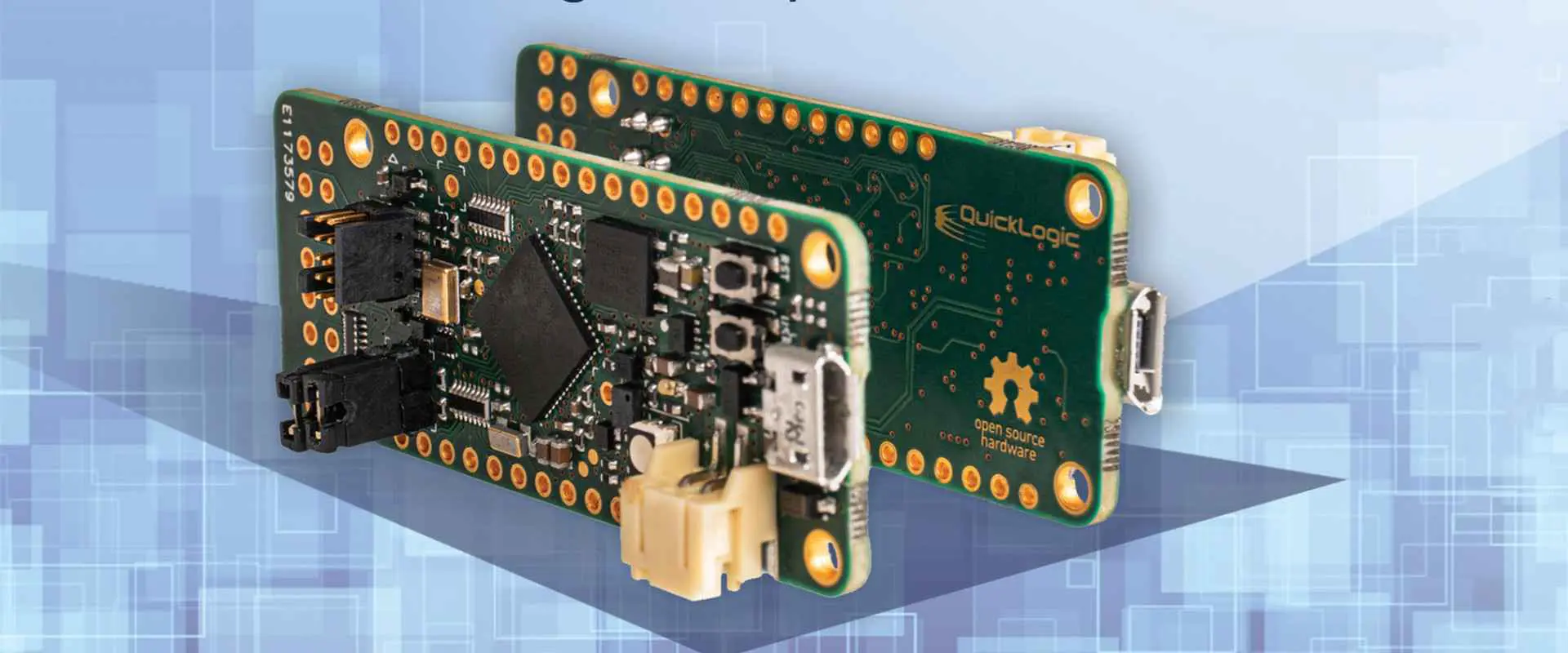
QuickLogic eclipse FPGA devices

QL6600ESPB516C, QL63254PT280I, QL66006PS484C, QL63254PT280C, QL66006PB516C, QL63254PS484C, QL66004PB516C, QL6250PQ208I, QL65007PB516C, QL6250PQ208C, QL65006PT280C, QL6250E6PS484I, QL65006PB516I, QL62507PQ208C, QL65004PS484C, QL62506PQ208C, QL65001PF100I, QL62506PB516C, QL6325GPS484C, QL62504PT280C4907, QL6325ESPQ208C, QL62504PS484C, QL6325EESPT280C, QL62504PQ208M, QL6325EESPS484C, QL62504PQ208C4626, QL6325E7PQ208C, QL62504PQ208C4464LA, QL6325E6PQ208C, QL62504PQ208C446, QL63256PS484C, QL62504PQ208C

QuickLogic Eclipse FPGA devices price fluctuation frequency

The price of QuickLogic Eclipse FPGA devices depends on the quantity manufactured and the market demand for that part. The price is stable and not subject to frequent changes. However, the price may vary by ยฑ10% over time.

Is there a minimum and maximum order quantity?

The minimum order quantity is typical $20K to $50K, depending on the device. The maximum quantity of an order is typically based on the factory capacity for that device and may be as high as several hundred thousand parts.

Conclusion

in conclusion, the QuickLogic Eclipse FPGA platform provides a complete set of semiconductor intellectual property (IP) and a high-level programming environment for FPGAs. The QuickLogic Eclipse FPGA platform is ideally suited for applications ranging from networking to multimedia, from industrial control to test equipment, and automotive, medical, and security applications.

The Eclipse Platform provides built-in support for embedded memory, serial interfaces (SPI, I2C, and UART), DMA controllers, and flash memory. The Eclipse Platform enables the use of a wide range of readily available integrated circuits (ICs) as programmable hardware peripherals. The QuickLogic Eclipse FPGA platform is well suited to applications ranging from networking to multimedia, from industrial control to test equipment, and automotive, medical, and security applications.

It has become increasingly popular for companies to develop their IP in-house, supplied by the open-source community. One of the critical initiatives to produce IP cores in-house is to control the entire design process better. QLogicโ€™s IP solution fully controls the design flow from specification, simulation, and synthesis through final implementation.

What are RF Cables? Definition, Types, Applications, and Assemblies

RF cable

Introduction

  • Definition of RF cables and overview
  • Role in transmitting high frequency signals
  • Applications in wireless communications, networks, aerospace, defense, etc.
  • Key parameters like frequency, attenuation, impedance
  • Types of RF cables and constructions
  • Assembling and connecting RF cables

What Are RF Cables?

  • Cables that carry radio frequency signals
  • Range from a few MHz to GHz frequencies
  • Used to connect equipment like antennas, radios, transmitters, etc.
  • Engineered to maintain signal integrity at high frequencies
  • RF currents flow through conductors

RF Cable Parameters

  • Impedance – typically 50 or 75 ohms
  • Attenuation – signal loss over cable length
  • Frequency range
  • Power handling
  • Shielding effectiveness
  • Connectors and terminations
  • Flexibility and ruggedness

Cable Types and Constructions

Coaxial Cables

  • Inner conductor surrounded by dielectric insulator
  • Outer conductor that acts as shield
  • Widely used up to 6 GHz

Types

  • RG-174 – thin, flexible up to 3 GHz
  • RG-58 – low loss up to 1 GHz
  • RG-8 and RG-213 – thick, high power
  • Semi-rigid – solid conductor, up to 18 GHz

Twinaxial Cables

  • Two inner conductors instead of one
  • Twists maintain balanced characteristics
  • Used for data transmission up to 10 Gbps

Triaxial Cables

  • Like coax but with extra shield layer
  • Very heavily shielded for noise immunity

Waveguides

  • Hollow metal pipe that guides RF waves
  • Used over 18 GHz where cables have excessive loss
  • Low signal loss even up to 100 GHz

Leaky Feeder Cables

  • Coaxial cable with periodic slots in shield
  • Radiates signal along length of cable
  • Used to distribute signals indoors for wireless systems

Applications of RF Cables

Wireless Communications

  • Antenna feeds
  • Connecting base stations
  • Distributed antenna systems

Wireless Networks

  • Connecting routers, access points, repeaters
  • Structured cabling in buildings
  • Data centers, server rooms

Broadcast TV/Radio

  • Studio wiring and antenna feeds
  • Portable equipment connections
  • Temporary outdoor setups

Aerospace / Defense

  • Airborne radar and avionics systems
  • Shipboard and vehicle communications
  • Missile guidance systems
  • Robotic systems control

Medical Systems

  • MRI and imaging equipment
  • Surgical device connections
  • Patient monitoring

Test and Measurement

  • Connecting test equipment like signal generators, oscilloscopes, spectrum analyzers
  • Anechoic chamber wiring

RF Cable Assembly and Installation

Electronic Cable Assemblies

Connectors

  • Wide variety of coaxial connectors
  • SMA, SSMA, TNC, N-Type, DIN, etc.
  • Precision machined contacts
  • Compatible with cable type

Attaching Connectors

  • Soldering
  • Crimping
  • Compression fittings
  • Specialized connection techniques

Routing and Securing

  • Avoid kinking or excessive bending
  • Secure along path without over-tightening
  • Use clamps, lacing, conduits
  • Leave service loops at connections

Avoiding Interference

  • Keep properly shielded and separated
  • Use crossover patterns to reduce coupling
  • Proper grounding and shield terminations

Weatherproofing

  • Special jacketing materials
  • Use drip loops to shed moisture
  • Seal connections to prevent ingress

Lightning Protection

  • Ground cables entering buildings
  • Lightning arrestors to dissipate strikes
  • Surge suppressors on equipment

RF Cable Testing

  • Loss measurements with VNA
  • Return loss / impedance
  • VSWR and signal reflections
  • Shielding effectiveness
  • Propagation delay
  • Power handling verification

Conclusion

  • RF cables are specialized to maintain signal integrity at high frequencies
  • Many types and constructions suit different applications
  • Proper installation and protection ensures optimal performance
  • Advancements continue to provide lower loss and higher frequencies

Frequently Asked Questions

What frequency ranges do common RF cable types cover?

  • Coaxial cables like RG-58 and RG-8 operate up to a few GHz.
  • Semi-rigid cables work up to 18 GHz.
  • Waveguides cover ranges above 18 GHz into 100 GHz+.

What are some key considerations when routing RF cables?

Avoiding sharp bends, managing cable length, securing cables properly, separating from noise sources, proper grounding and shield termination are vital for signal quality.

How are connectors attached to RF cables?

Coaxial connectors are typically attached by either soldering, crimping, or compression techniques. Proper tools and techniques ensure connections meet RF requirements.

What are shortcomings of RF cables compared to wireless?

Cables have distance and bandwidth limitations due to signal loss in conductors. But cables provide guaranteed quality and security not impacted by external interference like wireless.

How can cables be weatherproofed for outdoor use?

Specialized jacketing materials like Teflon resist weather effects. Drip loops allow water to run off. Sealing connections prevents moisture ingress. Proper installation avoids water wicking into cables.

How are they made?

There are many types of RF cables. They consist of various materials, including copper, glass, and plastic. Some cables transmit RF data, and others send audio and video signals. The type of cable you choose depends on how your station will handle different signals and protocols. When designing a station’s physical layer, you need to use the ISO recommendation for recording data through your cable.

What are they used for?

The main purpose of RF cables is to connect two or more pieces of equipment. They are beneficial in radio, where the signals travel through the air and then connect to an antenna. You use them on TV to create a signal from your antenna to the television. It then bounces back from the antenna pcb again for other TVs to receive. We use them for military purposes on many satellites that transmit information through space.

What do they look like?

We make RF cables from various materials, but they all have qualities that make them similar. They have to be resistant to radiation, like the signal traveling through them. They must also be light and flexible to avoid problems during transmission or receiving. The best RF cables can also withstand extreme temperatures and pressures during transmission. The cable is usually gold-plated to ensure a tight connection, which increases the range and performance of the wire.

How RF cables work

All RF cables have specific characteristics that make them effective ways to send data. The type of cable chosen depends on how the station sends and receives data. RF cables can be a few inches long or as long as 50 miles. The ability to send data over long distances is essential when sending live video from a stadium or concert hall to millions of people. Some cables are glass and plastic, then fired into steel powder. It creates a cable that can handle high temperatures and radio waves. All you need to know about RF cables is how we make and use them. Understanding the physical layer of a station is essential in designing an efficient protocol.

In an RF transmission, it’s critical to have a cable that can pass a signal along without getting damaged. In the end, all you need to know about RF cables is what they do and how they accomplish it.

Benefits of RF Cable

rf cable antenna

1. To transmit information over long distances:

In the case of RF cables, they connect a transmitter and a receiver. The transmitter emits electromagnetic signals, and the receiver receives them. Data can move through walls or even through wires, but with the help of an RF cable, the information can travel very far.

2. To create a secure connection:

In general, your computer may not want to share personal data with another device. For example, it happens when sending sensitive information such as credit card numbers over an open network Wi-Fi connection.

3. Provide a secure connection between two devices:

The purpose of an RF cable is to provide a secure connection between two devices so that no one can access or change the data in transit.

4. Use in transmitting TV signals and radio waves:

RF cables are usually attached to a device capable of broadcasting and receiving signals. Radio waves move through the cable to the transmitter, which sends these signals to a television or other device.

5. RF data transfer:

We use RF cables to transfer data from one device to another. They pass the signal from one device to another through a physical connection to transmit and receive data over long distances. This way, there will be no need for an extra power supply.

6. Provide a stable connection between two devices:

While the connection may not be secure, the data can still move without interference or transmission breakdown.

7. The protection of the cable against outside radiation is critical to transmission:

We usually make RF cables using copper wire, which helps protect devices against outside radiation. In addition, copper is a very resilient material, and it is also resistant to corrosion.

RF Cable vs. Coaxial cable

A coaxial cable is a type of cable used for radio signals. It acts as a transmitter to send radio waves and acts as a receiver to pass through the signals coming from other sources. We also use it to connect one device to a system. RayMing PCB & Assembly make coaxial cables of copper, a very efficient conductor of electricity.

The difference between a coaxial cable and an RF cable is that a coaxial cable is helpful for just transmitting radio signals. It cannot send data using RF or other types of electromagnetic waves. So the only distinction between the two cables is that they serve different purposes, but they consist of the same materials.

It is essential to use RF cables to transmit radio waves because they can pass through walls and other conductive materials. It is also crucial that you use a high-quality copper cable, the material used for coaxial and RF cables.

Another type of cable that we use for transmitting radio waves is an optical fiber cable. An optical fiber is a type of cable made of glass, which makes it very durable and light in weight. In addition, it can carry a considerable amount of data because it has a high capacity for data transfer, which makes it very efficient.

When you use RF cables to transmit data over long distances, the range can be as low as 10 meters and varies depending on the quality of the connection.

The Difference Between RF Cable and HDMI Cable

A high-definition multimedia interface (HDMI) cable transmits high-definition video, audio, and other data. It is ideal for use in theater systems and home entertainment systems. The main difference between an HDMI cable and an RF cable is that HDMI cables can transmit various types of media data. RF cables can transmit radio signals. RF cables cannot transmit audio or video data to the same HDMI cables because they do not support digital signals. The types of data transmitted through an HDMI cable may differ from one manufacturer to another, but it can support up to eight audio channels. HDMI cables are usually essential in connecting devices such as computers or television. An RF cable can transmit radio, television, and military systems. But you can also send data over long distances. It doesn’t allow for audio or video information transmission. But it is still possible to do it using other means.

It is essential to use an HDMI cable to send audio and video data because it is a less expensive alternative to other cables. When using an HDMI cable, you only need to make sure that you buy a quality cable that transmits high-quality signals. We can also use it for sending Ethernet signals.

There are many different types of RF cables. They have different designs depending on the purpose they serve. However, they all have something in common. These cables can transfer data over long distances irrespective of their other materials. It depends on the device they are being used to connect. The most common types of RF cables include telephone and coaxial cables. A telephone cable connects two devices through a physical connection. A coaxial cable connects two devices wirelessly.

Specification of good RF Cables

1. Impedance Specification

It is essential to buy an RF cable with an impedance specification that matches the impedance of your cable. Impedance can define the resistance of your cable towards the flow of alternating current. We measure it in ohms. The most commonly used values for impedance are 50 and 75 ohms, but you can also find cables with a value higher than 100 ohms. A standard RF cable impedance depends on the signal’s frequency.

2. Frequency Response

We use frequency response to define the bandwidth of your cable. It determines the rate at which your cable can transmit the signal without distorting or interfering with it. Depending on how fast your signal needs to move, we measure it in hertz, kilohertz, and megahertz. The most commonly used values range from 30Hz to 4000Hz. But some cables can work even at higher frequencies such as 10MHz and higher.

rf cable types

3. Phase Stability

We use phase stability to define the phase shift in your cable. If there is no phase shift, it means that your cable can handle data without distortion. Phase stability of a standard RF cable does not change with time.

4. Shielding

It is essential to use a shielded cable to protect digital signals from interference. It usually consists of copper wires or conductive materials suitable for transmitting radio signals. However, they are not always made of copper because they would be too heavy and difficult to work with. Some shielding consists of aluminum or aluminum foil. We can use it with an antenna wire. They prevent unwanted electromagnetic radiation from moving through the cable.

5. Attenuation Specification

We use attenuation to define the energy loss in your cable over a particular length. The main components that cause attenuation in your cable are the cable material’s resistance and capacitance. We can express it in DB/100m or pico-watt per meter. The most commonly used values are 0, 1, 2, and 4db/km, depending on how fast your signal needs to move. But it also depends on how long the cable must be.

6. Power Specification

We use power specifications to define the maximum power your cable can support. We measure it in volts and watts. The most used values are 0, 2, 6, and 12 volts, but you can also find cables with a value higher than 50 volts. Wide ranges of RF cables are available with different power specifications.

7. Temperature Stability

It is essential to buy an RF cable with a temperature stability specification to use it in different conditions and temperatures. Temperature specifications are in dB/ยฐC, where we define the -10 dB as a standard value, while we use the 0 dB to define how we can lose little energy.

8. The quality of the picture

The quality of the picture depends on various factors. For example, if you buy a cable for transmission through a digital video recorder, you should look for the highest image quality possible. However, you need it to send television signals through a coaxial cable connecting two devices for good image quality. The price is more critical when choosing an RF cable because they determine the transmission speed of your signal.

9. External interference

Suppose you will be using your cable in an external interference source environment. In that case, you must choose a cable that can handle the interference and not let it go through the wire. If you don’t need the cable to be connected all the time, using a cable type that is less likely to break or cut out may be a good idea.

10. The quality of the audio

It is essential to make sure that you buy a cable with good audio quality so that the sound of the source device is clear. Your television will not have as effective a picture if there is interference in the audio signal. The RF cable is very useful for transmitting audio, but it doesn’t allow you to do anything else. It cannot provide additional power for the sound it transmits. Therefore, the audio quality depends on what you are using to receive the signal.

11. Signal Types

If you are using a cable to transmit a signal of a specific type, it is essential to choose a cable that can handle the type of signal. For example, if you are recording digital television signals, your cable has to send these signals without distortion. We use cables for different purposes, and it is essential to understand how we can use each type. For example, RF cable can transmit HD signals, but not all RF cable types can.

12. Accessibility

It is essential to buy a cable that is accessible because it will be easier for you to install and use it. Specific RF cables are not too accessible, and we can use them only if you have the correct equipment to install them. You should understand these types of cables and use them properly. But if you find an RF cable with all the specifications listed above, it should be suitable for your needs.

13. Diverse needs

There are many types of RF cables that we can use. You must make sure that it suits your needs and the type of signal you are transmitting over your cable. You must know what type of signals you need to transmit before buying an RF cable because not all cables can handle all kinds of signals.

14. The covered distance

You must make sure that you buy a cable that can transmit signals between different distances. It is essential to buy an RF cable that can easily send signals over longer distances because it is more cost-efficient.

15. Cable installation

We usually install RF cables manually, which is not easy to install. If you do not have the right tools, it will be very hard for you to install your RF cable. This is without causing damage to the device or the signal it transmits over a distance.

16. Noise

Most RF cable types have noise, but it depends on how much noise the cable can handle. If you cannot install your cable correctly and use it efficiently, this can also be a problem. The best thing to choose is a cable with very low noise that provides clear audio signals with no interference.

17. Speed in data transfer

The speed of data transfer depends on the cable type you are using. Your cable can transmit data signals at a very high speed, but only if it is a good quality cable with the correct installation. You should buy a cable that can support the transmission of your signal. It does not cause any distortion, resulting in decreased data transfer speeds.

18. Cost

The cost of an RF cable depends on the cable’s length and the other specifications it has. You should be careful when buying an RF cable because you can easily spend a lot of money on your purchase if you buy a not suitable cable for your needs. If you find a good quality, long length of RF cable, it can be costly. But if you find one short and does not have any extra specifications, it will probably cost less than others.

19. Cable terminals

Choosing a cable with the right terminals for your device is essential. If you do not buy the right type of cable, then it will be hard for you to connect it to your device and use it. Therefore, you should check your device specifications before buying an RF cable to ensure that we can use it with the terminal type of your device.

20. Potential loss of the transmission

You should ensure that the cable does not lose any transmission signals when transmitting them over a certain distance. Of course, different factors can cause the loss of signals. But you should choose a cable that can transmit your signal and ensure that we do not lose signals in the transmission.

21. Multiple functions

You should choose an RF cable with more than one terminal to make it easier for you to connect it to your device. In addition, purchasing a dual-type of cable will make it easier for you to connect the cable to your device and use it efficiently.

Cable for Wireless Transmission

A cable with the right specification can transmit signals over a certain distance without distortion.

If you want to transmit signals over extended distances, then you must choose an RF cable that is long enough to cover the distance. Some RF cable types can be costly, but they are usually long and can transmit your audio and video signals over a large area.

The best thing about these types of cables is that we can use them in interior homes and outdoors.

Application of RF cables

There are various types of RF cables with different combinations of features. However, the features are essential, and you should check that we can use the cable for your application.

1. RF equipment in medicine and healthcare

We can use RF cable in medicine and healthcare. They transmit signals over long distances without causing any damage to the medical equipment. We use these cables correctly and can work without causing any problems. They can transfer data signals at a very fast speed, but only if they are correctly installed.

2. Satellite communications

The satellite communications industry uses RF cables to send data signals over long distances. This industry is very complex, and you should understand how the whole process works before choosing a specific type of RF cable.

3. Ships and navy communication systems

Boat communication systems use RF cables to send signals over large distances without causing problems. This industry uses satellite communication systems. But we can use RF cable on boats and vessels. It has a built-in feature that allows transmitting signals without causing any distortion.

4. Military and space application

The military and space industry uses RF cables to transmit signals over large distances without causing any problems. However, this industry is very complicated, and you should check the specifications of your RF cable before purchasing it.

5. Wired telephone and communication networks

Wired communication networks use RF cables to send signals over long distances with high speed. This industry uses RF cable because it is safer and more effective than other cable types.

6. Aerospace industry for accurate communication equipment

The aerospace industry uses RF cables to send signals over large distances without causing any distortion. However, this industry is essential and the equipment used has to be very accurate, or it can cause problems in the communication systems.

7. Professional RF test and measurement systems, development units, and labs

Professional RF measurement systems use RF cables to send long distances with low noise and distortion. This industry uses particular cables designed to transmit signals without causing any distortions.

8. Domestic applications

The domestic application industry uses wireless transmission to send signals over long distances. This type of installation is very common, and many people who use these are unaware of them.

9. Mobile communication networks

Mobile communication networks use RF cables to send low noise and distortion signals over long distances. To use these systems, you need an RF cable with a specific and good performance on your device.

10. Radio communication systems

Radio communication systems are the type of RF cable used by the broadcasting and communication industries. These systems use RF cables to transmit low noise and distortion signals over long distances.

Conclusion

The RF cable industry is very large, but you must make the right purchase. Before purchasing the cable, check your device to ensure it will connect to the cable. Then, choose an RF cable with the right specifications and send your audio and video signals without causing any distortion.

You must choose a reputable brand with a good reputation. It will have better cable quality and high-performance features.

What is SMT Soldering Process? Step By Step

SMT soldering Process

Introduction

  • Definition of surface mount technology (SMT) soldering
  • Advantages over through-hole technology
  • Crucial process in PCB assembly
  • Overview of steps from paste deposition to reflow
  • Details on each stage of the process

Defining SMT Soldering

  • Method of attaching SMT components to PCB pads
  • Solder paste deposited on pads, then component placed
  • Adhesive holds component in place temporarily
  • Final solder joint formed by reflowing the paste
  • Used for components like:
    • Resistors, capacitors
    • SOICs, QFPs
    • BGAs, CSPs
    • 0201 and smaller passives
  • Enables:
    • Miniaturization
    • High component density
    • Automated assembly

SMT vs Through-Hole Assembly

SMT Process Engineer
ParameterSMTThrough-Hole
Component typesChips, passives, ICsLeaded components
PCB requirementsPadsDrilled holes
Paste depositionStencilWave/selective solder
Component attachSurface padsInserted in holes
Soldering methodReflowWave or selective solder
ProcessAutomatedManual labor intensive
Density achievableVery highLimited by hole spacing
ReworkabilityChallengingRelatively easier
Thermal managementViasLarge thermal planes
CostHigher initialLower initial, higher long-term

SMT Process Step-By-Step

1. Print Solder Paste

  • Use stencil to apply precise amount onto pads
  • Stencil openings match copper pad layout
  • Squeegee spreads paste evenly over stencil
  • Common pastes:
    • SAC305 (Sn/Ag/Cu)
    • Sn/Pb (being phased out)
  • Key parameters:
    • Print speed
    • Pressure/angle of squeegee
    • Stencil wipe frequency
    • Print gap

2. SMT Component Placement

  • High speed pick and place machines
  • Precisely place components on wet paste
  • Split second per component placement
  • Advanced vision systems for alignment
  • Optimizing component placement:
    • Group by package size
    • Minimize tool changes
    • Optimal board flow path

3. Adhesive Curing

  • Reflow will happen later
  • Adhesives cure components in place
  • Avoid tombstoning before reflow
  • Typically light heat or UV curing

4. Solder Paste Inspection (SPI)

smd soldering paste
  • Verify paste deposits before reflow
  • 2D or 3D optical inspection
  • Detect defects like:
    • Insufficient paste
    • Too much paste
    • Smears
    • Blockages
  • Take corrective actions or clean stencil

5. Reflow Soldering

  • Heat applied to melt solder paste
  • Forms permanent solder joints
  • Conduction, convection, radiation heat
  • Typical profile:
    • Ramp up
    • Soak zone
    • Reflow peak
    • Cool down
  • Profile must suit components
  • Common methods:
    • Convection reflow oven
    • Vapor phase reflow
    • IR/radiant heat

6. Post-Reflow Inspection

  • Verify all joints formed properly
  • Look for:
    • Shorts
    • Opens
    • Insufficient heat or wetting
    • Other defects
  • Automated optical inspection (AOI)
  • X-ray inspection

7. Cleaning

  • Remove flux residues after reflow
  • Improve aesthetics and prevents issues
  • Solvent cleaning with agitation
  • May impact component susceptibility

SMT Line Optimization

SMT Machine
  • Balance speed vs yield tradeoff
  • Component sequencing for minimum changeovers
  • Optimization software to maximize uptime
  • Maintenance and changeover procedures
  • Real-time monitoring and feedback

Defect Prevention and Control

  • Sources of defects:
    • Design
    • Materials
    • Process
    • Handling
  • Tightest control at process level
  • Defect elimination strategies:
    • Statistical process control
    • DOE optimization
    • Anomaly detection
    • Traceability systems

Quality and Reliability Testing

SMT soldering Process
  • ICT – tests shorts, opens, values
  • Flying probe electrical test
  • Burn-in stress testing
  • X-ray and coefficient of thermal expansion analysis
  • Vibration, drop, and shock testing
  • Process audits and sampling

Conclusion

  • SMT enables miniaturized, high density PCB assemblies
  • Multiple stages from paste print to reflow
  • Each step must be optimized for yield and reliability
  • Overall process control and monitoring is crucial
  • Defect elimination and quality testing ensures performance

Frequently Asked Questions

What is the most critical SMT process step?

Reflow soldering is generally considered the most crucial step since this permanently forms the solder joints attaching components. The profile must be optimized to suit all component requirements.

How small of components can be soldered with SMT?

SMT can reliably solder extremely small components like 01005 passives, microBGAs, and even microchips with tolerances down to 15 microns or below with advanced techniques.

What are common SMT defects?

Insufficient solder and open joints, bridges and shorts, tombstoning, skewed parts, solder balls/beading, heat damage, missing components, bent leads, are examples of potential SMT assembly defects.

What is the key advantage of SMT vs through-hole?

Higher component density, miniaturization, and suitability for automation give SMT a density and throughput advantage. However, through-hole assembly can utilize lower cost components and enables easier rework.

How can SMT solder joint quality be inspected?

Automated optical inspection and 3D SPI immediately after soldering can catch many defects. For internal inspection, X-ray laminography provides detailed 3D views of hidden solder joint quality.

To achieve the best electronics, one needs to solder. This process is often done with a soldering iron and leads to success if done properly. But how do you know how to solder? Here, I will introduce you with the SMT soldering process, including a step-by-step guide on how to put together a piece of electronics.

What is SMT soldering?

SMT soldering is the process of soldering electronic parts onto a circuit board, which is mostly done by hand. SMT is an abbreviation for “Surface Mount Technology”. This means that we do the solder assembly without a soldering iron, but instead with a machine called a “solder reflow oven”. The steps and materials used to SMT solder include the following.

When Is SMT Soldering Used?

FULL PCB MANUFACTURING Quote

SMT soldering can be helpful in many ways, including using as a hobby or at work. The use of SMT soldering will increase your knowledge in electronics and electricity. Itโ€™s also a good way to learn how to solder when you are starting out.

The reason SMT soldering is helpful at work is because of the low cost and high speed when producing the products.

What are the parts of SMT soldering?

There are two key things you need for SMT soldering: a circuit board and electronic parts.

For the circuit board, it is essential to use a silk-screened PCB (Printed Circuit Board) with plated holes (not tin). Usually, this type of circuit board can go for $1~$3 dollars in local Makerspace or online. To further save cost, you can also make your own printed circuit board, by drawing your circuitry on copper foil. Another option is to use a copper-clad board, which looks like a thin sheet of copper. It is acid-etched or sand-blasted with holes and traces.

For the electronic parts, you can find them online easily. For example, Rayming PCB & Assembly has a wide range of SMT parts at reasonable prices. Other places include eBay or Amazon. You should be careful when choosing these parts, as there are some which help specifically in prototyping and we cannot use in production parts.

Stuff you need

Before you start, you will need:

A soldering station

This is the current state of art in electronics manufacturing. It consists of a hot air furnace that heats up solder, a soldering iron that allows heating of the pasted joint, and a soldering tip which will melt the solder. The key to using a soldering station is to heat up pieces separately and avoid overheating them. You can use either the temperature mode or the time mode.

Some solder

This is the main ingredient in recreating this process. Solder consists of tin and lead, which are both an alloy with silver. Solder is normally a bit cheaper than other types of welding materials, and it has a better melting point than steel.

A soldering iron

This is the current state of art in electronics manufacturing. It consists of a hot air furnace that heats up solder, a soldering iron that allows heating of the pasted joint, and a soldering tip which will melt the solder. The key to using a soldering iron is to heat up pieces separately and avoid overheating them. You can use either the temperature mode or the time mode.

A piece of circuitry

An electronic circuit board is usually printed with various layers of metal with holes thats are full solder to connect to all the parts together. Circuit boards have a variety of shapes and sizes, depending on their function. You can use any type of printed circuit board; I will show you how to make a simple LED circuit board here.

A circuit diagram

There are many ways of using electronic components. Each design has its own merits, but most printed circuit boards require a schematic to read the connections of the wires and where they will connect to the solder. The circuit diagram is often presented as numbers on a grid.

Make SMT Soldering:

Step 1: Preparation

Assemble your tools appropriately (soldering iron, solder iron etc.) (see image below for more details). We must place solder in a temperature safe container to avoid damage from heat and oxidation once it becomes molten. Then find an area to work that is free from distractions. We can do this in the garage or workshop.

Step 2: Preparation of copper board

Find a copper board with the right size and shape for your circuit design. For example, a standard breadboard is good for prototyping, but if you want to make something more complex, you should use an integrated circuit board (or “chip” board). Chip boards are more expensive than breadboards, but it’s often easier to solder components on them because there are less wires that need to connect. For example, SMD LED soldering requires a chip led. We use solder paste here as well as it helps in stabilizing joints and making them watertight.

Step 3: Mixing of the solder paste

To mix the solder paste, first make sure that you switch off both of your soldering iron so you do not burn yourself. Remember, solder paste is extremely hot when it comes out of the nozzle. If you have a refillable hard solder gun, you can use the syringe to fill up some solder paste and simple push it down into a microwave safe container.

However, if you have an integrated circuit laser gun, make sure to screw off the tip off with a screwdriver before attempting this as it will burn your fingers. In this case, you will need to melt the solder paste first in a microwave or a small pot then mix it with the solder. It is best to hold your soldering iron with one hand and mix with the other as it is hot and can cause burns. After mixing, use a clean spoon or spatula to help melt the solder so that your circuit connects correctly.

Step 4: making SMT

Now we are ready for action! Switch on your soldering iron and put it on temperature 40ยฐC~45ยฐC. Heat up several pieces at once. Solder melts at 113ยฐC. So, you must heat up several parts simultaneously. If you place them too close to each other, they will melt and you will have difficulty in moving the remaining parts.

As a test, take one of the parts and melt it on the tip of the soldering iron. If it is solid enough, then you can move on to more parts. If not, repeat until all your parts merge together.

Once you have all the parts joined, then use a piece of solder to connect all the pieces together. Take some time to test your work and check for any solder connecting to the iron. If so, remove by placing more solder on the joint.

Using this process, you can make your prototype. It does not require much skill, but it does take some time and patience. If it is your first time, it is probably best to make one part at a time and check for errors. The next step to making your own product using SMT is how the solder paste comes from the gun onto a pad. This video guide below will show you how to do this:

Conclusion

In this project, you have seen how you can use the basic components and simple soldering to make your own low cost PCB board. In addition, you have learned how to solder using a hot air soldering station and how to solder using an integrated circuit laser. You will also know the main ingredients in recreating the process of reflow soldering.

The Impact of Shengyi SF305 in Flexible PCB Fabrication

Shengyi SF305 flex pcb

The advancement in the PCB industry has resulted in the recent development in PCB material. Todayโ€™s PCB materials are designed with great functionality and high reliability in mind. Shengyi PCB materials are examples of these. When it comes to quality, Shengyi is the right PCB product to opt for. In this article, we will be discussing one of Shengyiโ€™s highly reliable PCB materials. The main focus here is the Shengyi SF305

What is the Shengyi SF305?

Shengyi SF305 is a halogen free PCB laminate with great thermal and electrical properties. Also, this PCB material adheres to the UL94 V-0 flammability standards. This material is lead-free compatible. Hence, it is safe for PCB fabrication. In addition, this material is free of toxic elements like PBB and Cr6.

Shengyi SF305 is a conductive material used to fabricate flexible circuits. Also, this PCB material is a flexible copper clad laminate. It is compatible with the RoHS directive. Shengyi SF305 is a sheet of flex PCB material. However, it is raw and unetched. This material can be treated in a similar way with 1oz copper clad. Manufacturers can achieve etching by using ferric chloride. Also, it features great flexibility and strength.

This material can work around small areas. Also, it is widely used in space demanding applications. Shengyi SF305 PCB material is useful in several consumer-grade electronics. This material is behind the fabrication of miniature devices.

What are the Properties of Shengyi SF305?

Shengyi SF305 PCB material is different from regular PCB materials. Also, this material features unique properties. These properties include:

Great chemical resistance

Shengyi SF305 has the ability to resist chemical elements. Therefore, this laminate is ideal for use in applications exposed to chemicals.

Stable Dielectric constant (Dk)

The dielectric constant of Shengyi SF305 is 3.6 at 10 GHz.  This property measures the ability of a material to retain energy in an electric field. The dielectric constant of Shengyi SF305 is ideal. Also, this value indicates the electrical performance of Shengyi SF305 PCB material. In addition, Shengyi SF305 maintains a stable Dk over a wide frequency range.

Dimensional stability

This property measures how a laminate can maintain its original size when exposed to various temperatures. The dimensional stability of Shengyi SF305 is -0.0684/0.0691% after etching. Also, this is a good value. Therefore, Shengyi SF305 PCB material can withstand varying temperatures without changing its size.

Electric strength

This measures the ability of a PCB material to withstand electrical breakdown. The electric strength of Shengyi SF305 is 110 KV/mm at D-48/50+D-0.5/23.

Stable dissipation factor

The dissipation factor of Shengyi SF305 is 0.028 at C-24/23/50. This value is stable and low. A typical PCB material should have a dissipation factor in the range of 0.02 to 0.01. Also, Shengyi SF305 can perform greatly in various environments and applications. Shengyi SF305 features a low dissipation factor which makes it a more efficient insulator.

UL94 flammability

Shengyi SF305 PCB material features UL94 flammability. This is a flame-retardant property. The UL94 is a standard for the safety of flammability of materials. Also, this standard requires that PCB materials shouldn’t be longer than 10 seconds.

Advantages of Shengyi SF305

Shengyi SF305 PCB material offers several benefits when used in applications. Some of its benefits include:

Halogen Free

Shengyi SF305 PCB material contains no halogen constituents. Also, it is completely free of halogen. Therefore, it is an environmentally friendly option for PCB fabrication. Halogen is a toxic substance for humans and the environment. Therefore, halogen free PCB materials are the standards for the PCB industry.

Compatible with EU RoHS directive

This PCB material is very compatible with the EU RoHS directive. Therefore, it is suitable for fabricating flexible circuit boards. The EU RoHS directive designs rules that prohibit the use of hazardous substances in PCB fabrication.

Great thermal performance

There are several factors that determine the thermal performance of a PCB material. Shengyi SF305 PCB material features great thermal properties which contribute to its thermal performance. Therefore, this material is suitable for applications that demand exceptional thermal performance.

Exceptional flexibility

Shengyi SF305 PCB material is a flexible copper clad laminate. Also, this material features exceptional flexibility. Therefore, it is widely used for fabricating flexible circuit boards. It is a reliable material for flex PCBs and semi-flex PCBs.

Great dimensional stability

This PCB material maintains its dimension when exposed to varying degrees of temperature. Despite its flexible nature, it hardly expands in size.

Applications of Shengyi SF305

Shengyi SF305 is a reliable PCB material used in some common applications. This material features properties that make them the best choice for these applications.

Mobile phone

You will find Shengyi SF305 PCB material in mobile phones. This material is commonly used for fabricating PCBs used in mobile phones.

Office Automation equipment

Office automation describes the various computer software and machinery for creating and storing data. OA equipment includes scanner, printers, and computers. You will find the Shengyi SF305 PCB material in these pieces of equipment.

Digital Camera

Flexible laminates are commonly used in applications that demand space savings and flexibility. You will find Shengyi SF305 PCB material in digital cameras. Also, this PCB material offers enough flexibility for this application.

VCR

VCR means videocassette recorder. Electronics manufacturer use flexible circuit boards when designing VCR. Shengyi SF305 is an ideal material for fabricating these boards. Also, this material features properties that make them ideal for use in this application.

Wearable devices

Shengyi SF305 PCB material offers great flexibility and space saving. Therefore, it is widely used in designing wearable devices. This material is available in body-mounted sensors, smart watches, and more. Also, this material has a bending ability. The Shengyi SF305 laminate can be easily bent in different shapes. Most wearable devices require rigid flex or flex PCBs.

Antenna module cable

This cable connects to different controls in the vehicle through a digital bus. Also, Shengyi SF305 laminate is widely used in designing antenna module cables. This is because it offers the flexibility required by this application.

Conclusion

This article has explained important details about Shengyi SF305 PCB material. It is not just a flexible laminate, it offers great properties. Therefore, this PCB material is a great material for some applications.

Everything You Need to Know About the Shengyi S1000h PCB Material

Shengyi S1000h PCB

The Shengyi S1000h PCB Material is different from other laminates you can use on your circuit board. It is no doubt that this laminate has some unique features like lead free compatibility and exceptional anti-CAF conduct.

In this article, you shall find out more about everything related to the Shengyi S1000h PCB. With its low rate of water absorption, this laminate has the ability to work effectively without any disruption from water. Read through this interesting article to broaden your understanding about this topic.

What is Shengyi S1000h PCB Material?

Unarguably, this is one of the types of laminates that works for multilayer circuit boards. With its unique features, the Shengyi S1000h can withstand harsh environmental conditions.

The Shengyi S1000h PCB Material is a kind of laminate that helps connectย the different layers of the circuit board. When fabricating the circuit board, there are layers one needs to bond. However, if you aren’t careful enough, the layers loosen up. One peculiar function of the Shengyi S1000h is to link up multiple layers of the circuit board.

This PCB laminate comes with great reliability performance and it can resist water. Therefore, it has the capacity to work without any glitch. Plus, this is one advantage with this type of laminate.

Although it is not only Shengyi S1000h you can use it on multilayer PCBs. Meanwhile, there are similarities between the Shengyi S1000-2 and Shengyi S1000h. Despite this, each of these laminates comes with their peculiarities.

However, let us consider the similarities between both kinds of laminates since you can use them both for various kinds of multilayer PCBs.

What are the Similarities Between The Shengyi S1000h and Shengyi S1000-2?

CAF Resistance

When it comes to CAF resistance, both laminates are similar. Their degrees in relation to CAF resistance are high. However, the degrees of this resistance are different in these laminates. Note that, they may both have CAF resistance, but they operate differently.

Thermal Resistance

In addition, this is another similarity between both laminates. They indicate so much thermal resistance. However, their levels of thermal resistance differ. This same goes to the varying degrees in their CAF resistance.

Low Water Absorption

Both laminates have low water absorption. This implies that there is prevention of water from entering these laminates. Therefore, water can’t easily penetrate into them. No matter the moisture, both laminates cannot easily get damaged.

Lead Free Application

Interestingly, the Shengyi S1000h and Shengyi S1000-2 have lead free compatibility. With similar FR-4 materials, one can easily fabricate these laminates. Although, there would be various degrees of usage of the materials.

Features of the Shengyi S1000h PCB Laminate

There are numerous characteristics of the Shengyi S1000h that you may not find in other laminates. Despite its similarities with the Shengyi S1000-2, it has its distinguishing features.

Note that the variations are mostly different in these Shengyi laminates. This implies that their conducts are basically different with varying levels of performance.

Exceptional Thermal Dependency

One unique feature of the Shengyi S1000h PCB Material is the exceptional thermal reliability. This implies its ability to work effectively in a high temperature environment. It still retains its stability under very high temperatures. This Shengyi S1000h can perform well in appliances withstanding high temperatures.

Low CTE

Well, the Shengyi S1000h comes with low Z Axis CTE. This implies that this laminate doesn’t have much expansion when the temperature increases. With varying degrees of temperature, the coefficient of thermal expansion maintains its stability.

Excellent Anti-CAF Conduct

The Shengyi S1000h has exceptional anti-CAF conduct which enables it to have much resistance to electrochemical abrasion. Thus, its IST enhances the performance.

Lead Free Compatibility

This class of laminate works with PCB boards which have no lead components. That is why its compatibility with the circuit board is based on lead free application.

Drillable Using Laser Machines

The Shengyi S1000h is drillable when you use laser machines. This is a distinct feature it has. Thereby, this laminate becomes easier to mount different sizes of holes using the laser machines to drill them.

Specifications One Considers When Using The Shengyi S1000h PCB Material

You need to consider the different specifications of this laminate when you choose it. In addition, you consider the main properties which your application needs.

Chemical Component

You should consider the probable feature of this laminate that may likely change towards any chemical reaction.

Electrical Element

Note that, you need to know how this laminate reacts to some electric field.

Mechanical Components

One needs to consider the physical components of the Shengyi S1000h PCB material that react to force. Therefore, one needs to consider the electrical and chemical properties at this stage. In addition, the physical component has tendency to change after force exertion.

Thermal Property

Also, it is important to consider the features that change as a result of exposure to varying degrees of temperature.

The Thermal Properties of The Shengyi S1000h PCB

Flammability

The flammability has to do with how the laminate can catch fire when exposed to ignition. As a result, you need to measure the propensity to which it is flammable.

Glass Conversion Temperature

At this point, one considers the glass transition temperature in relation to how this Shengyi S1000h changes when exposed to heat. However, you should consider some factors like TMA, TSC, and  DMA in varying degrees in exposure to heat.

Thermal Stress

This implies that you consider the reduction in dimension in relation to reduction in temperature. Also, you  consider how dimension increases when the temperature goes up.

Degradation Temperature

Also, when you apply heat on your Shengyi S1000h, you need to consider some degrading chemical changes which occur on it.

Conclusion

The Shengyi S1000h PCB Material is a type of laminate that can bond layers together. With its special features, it has the ability to retain stability under high temperature.

Also, this laminate is durable and can connect multilayers on the PCB firmly. It has hot air solder level surface finish and lead free surface finish as its types of surface finishes.

Impacts of Isola Astra MT77 in the Fabrication of Advanced Circuit Boards

Isola Astra MT77 PCB

With the advancement in the 5G world, mm-Wave applications keep increasing. Therefore, the demand for advanced PCB material will increase over time. Also, 5G technology will increase the demand for low loss lead free compatible PCB laminate. However, this type of laminate will add more value to the industry.

Isola Astra MT77 PCB material has become popular among PCB manufacturer. Also, this material is widely used in applications like mm-Wave systems.

What is Isola Astra MT77 PCB Material?

Isola Astra MT77 is a low loss laminate and prepreg. This PCB material is compatible with FR$ processing. Also, it offers exclusive physical properties which include higher temperature range and broad operational frequency. Furthermore, this PCB material is commonly used for mm-Wave and RF/microwave applications.

This PCB material is useful in radar applications for automotive. Also, Isola Astra MT77 is useful in lane departure warning. This prepreg and laminate material provides great electrical features like enhanced dielectric constant. This Dk is within a range of temperature of -40 degrees Celsius and +140 degrees Celsius.

Furthermore, this low loss material features a dissipation factor of 0.0017. Most mm-Wave frequency band applications prefer ultra low loss materials. Also, Isola Astra MT77 is a great alternative for PTFE materials. This is because it is cost-effective.

Properties of Isola Astra MT77 PCB Material

High Tg value

The glass transition temperature (Tg) value of Isola Astra MT77 is between 190 and 200 degrees Celsuis. This high glass transition temperature is ideal for RF/microwave applications. Materials with high glass transition temperature. A high TG material features high temperature durability.

High Td value

The decomposition temperature (Tg) of Isola Astra MT77 is 360 degrees Celsius. This high Td value guarantees greater thermal performance.

Stable and low Dk

This materialโ€™s dielectric constant is 3 at both 2GHz and 10GHz. Isola Astra MT77 PCB material features a stable Dk over a wide frequency range. This dielectric property helps to maintain signal integrity when used in mm-Wave frequency band applications.

Low Dissipation factor

This ultra low loss material features a low dissipation factor of 0.0017 at 2 GHz and 10 GHz. Materials with low dissipation factor have better insulator systems. Therefore, this material reduces signal loss in applications.

Flexural strength

Flexural strength helps to measure the ability of Isola Astra MT77 to withstand mechanical strain. Isola Astra MT77 has a flexural strength of 49 ksi when it is in a lengthwise direction. Also, it has a flexural strength of 38 ksi in a crosswise direction.

Very low water absorption

The water absorption rate of Isola Astra MT77 is 0.1%. Therefore, this material can withstand a humid environment. Also, it absorbs water at a very high rate.

High Surface resistivity

This measures the insulation or electrical resistance of a laminateโ€™s surface. The surface resistivity of Isola Astra MT77 is 1.33 x 10^5 Mohm. This surface resistivity is high.

Advantages of Isola Astra MT77 PCB Material

Isola Astra MT77 is a PTFE laminate that offers exclusive advantages. This PCB material is different from other PTFE materials. It offers advantages such as:

RoHS Compliance

This material is compatible with FR-4 processing. Therefore, it is a flame retardant material. Also, this material is RoHS compliant. Therefore, it is safe for use in the environment.

High dimensional stability

Isola Astra MT77 maintains a stable dimension when subjected to varying temperatures. Dimensional stability refers to the ability of a PCB laminate to maintain its size when exposed to varying degrees of temperatures.

Wide-spread industry recognition

This material adheres to many PCB industry standards. Also, it adheres to the UL94 V-0 flammability standards.

Ultra low loss

Isola Astra MT77 is an ultra low loss material that features low Dk and Df values. Low loss materials offer better performance when used for PCB fabrication. Therefore, low PCBs are ideal for applications where impedance considerations and signal integrity are important.

Shorter lamination cycles

Sequential lamination is an important manufacturing technique in PCB fabrication. Isola Astra MT77 requires shorter lamination cycles. Modern PCBs are now becoming smaller. Therefore, shorter lamination cycles are crucial. PCB materials with fewer lamination cycles cost loss.

HDI technology compatible

HDI means high density interconnect. This technology is fast-growing in the PCB industry. These boards always have microvias that are o.006 or lower in diameter. Therefore, the Isola Astra MT77 is compatible with the HDI technology. This material features higher circuitry than other traditional PCB materials.

Cost effective

This material is a cost-effective option to other microwave laminates. Also, it doesnโ€™t require plasma desmear. Therefore, this reduces the cost of manufacturing this material. Isola Astra MT77 helps to strike an optimal balance between performance and cost.

Applications of Isola Astra MT77 PCB Material

The Isola Astra MT77 is useful in several applications. This PCB material is worthy of use in the RF/microwave applications. It has proved to offer better functionality than other RF/microwave PCB materials. However, it is ideal for use in other applications.

Aerospace and defense

Isola Astra MT77 PCB material is frequently used in the aerospace and defense sector. This material features a stable Df and Dk over a wide frequency range. Also, it offers thermal reliability. Thermal reliability and signal integrity are crucial in designing aerospace and defense devices.

Automotive and transportation

Isola Astra MT77 is widely used in radar application for automobiles. This material is gaining popularity in this industry. There is a need for this material in applications involving pre-cash and adaptive cruise control. Also, it is useful in applications that demand blind spot detection.

Radio frequency and microwave

The wireless market depends on this ultra-low loss material. This is because this material features great electrical, mechanical, and thermal features. Also, there is a rising demand for more bandwidth and speed in this application. Therefore, Isola Astra MT77 provides optimal benefits in this field.

Conclusion

The demand for advanced PCB materials will continue to increase. The Isola Astra MT77 PCB material is a great solution to high performance applications. This article has explained everything you need to know about this material.

Important Facts You Need to Know About Isola FR406

Isola FR406 PCB

Several PCB materials are available for PCB fabrication. However, not all materials guarantee functionality and reliability. Therefore, it is important to know more about PCB materials. In this article, we will be looking at one of the best-quality PCB materials for your PCB fabrication. The Isola FR406 is our focus in this article.

What Does the Isola FR406 PCB Material Mean?

The Isola FR406 PCB material is an epoxy resin material designed by Isola. The composition of this material enables it to be suitable for multilayer PCBs fabrication.

Also, this laminate features a stable dielectric constant and high glass transition temperature. This laminate isnโ€™t only ideal for multilayer boards; it also works for single sided PCBs.

What Properties Does Isola FR406 Offer?

Isola FR406 PCB material offers exceptional properties. These properties contribute to its high performance.

High glass transition temperature

The Tg of Isola FR406 is 170 degrees Celsius. Therefore, this PCB laminate features a high glass transition temperature. Also, it is ideal for high performance applications. High Tg material plays a crucial role in PCB fabrication. This property contributes to the thermal performance of a circuit board.

Low Z-axis CTE

The Z-axis CTE of this material is 60ppm/ยบC before glass transition temperature. The CTE after glass transition temperature is 250ppm/ยบC.  Therefore, Isola FR406 offers low coefficient of thermal expansion.

Low and stable dielectric constant

The dielectric constant of Isola FR406 is 3.93. This means that Isola FR406 PCB material features a low dielectric constant. Also, this electrical property indicates that this material is suitable for high frequency applications. In addition, Isola FR406 can reduce electric power loss when used in any applications.

High Decomposition temperature

The decomposition temperature of this material is 300 degrees Celsius. Therefore, Isola FR406 PCB material will chemically decompose when it operates above 300 degrees Celsius. The decomposition temperature of this material is high.

Square weave E-glass reinforcement

Isola FR406 PCB materials features square weave E-glass reinforcement. Therefore, this improves the mechanical properties of this material. Isola FR406 features a material made of electronic glass fiber cloth.

What is the Significance of Relative Thermal Index (RTI) in Isola FR406?

RTI plays a crucial role in determining the performance of a PCB material. This index describes the highest service temperature at which Isola FR406 remains within limits over a long time. Also, it defines the ability of a PCB material to retain thermal degradation. Therefore, this index specifies the maximum temperature you can expose Isola FR406 to avoid negative effect on its performance.

Isola FR406 is a high-frequency PCB material will generate high temperature conditions. Any failure in high temperature applications can have a negative impact. Therefore, it is important to utilize the appropriate material. Also, ensure the CTE of this laminate conforms to other materials.

Therefore, this protects Isola FR406 laminate form any damage. The relative thermal index is an important property to consider. In addition, the MOT (Maximum Operating Temperature) is a UL rating that backs RTI. It indicates the maximum temperature a PCB construction can withstand without changes in its properties. However, the RTI of Isola FR406 must exceed MOT.

Resin Systems in Isola FR406

There are several resin systems used in Isola FR406. However, the commonest resin systems are epoxy-based. The different types of epoxy resin systems are:

Tetra-functional modified systems

This epoxy resin system offers a high Tg value due to its enhanced cross-linking. Also, this system provides enhanced resistance to solvents and chemicals used in Isola FR406 manufacturing.

Thermally conductive epoxy resin systems

These resin systems features reasonable Tc values. The normal Tc for these systems varies from 1 to 3 W/m/K. Also, these systems use thermally conductive fillers. In addition, they incorporate a resin technology that is free of lead. Also, these systems encourage heat transfer through the laminate.

Di-functional epoxy resin

This begins with brominated bisphenol-A and adds fillers and accelerators. There are different di-functional epoxies. These are low-end di-functional systems and modified di-functional systems. The low-end system has a Tg between 110 to 130 degrees Celsius. The modified systems feature multi-functional and tetra-functional epoxy resins. Therefore, the Tg ranges from 135 to 160 degrees Celsius.

Low-flow epoxy systems

These systems have a restricted flow. Therefore, this makes them ideal for rigid-flex Isola PCB fabrication. Also, they are ideal for heat sink bonding. However, they have various Tg values.

The Effects of Heatup Rate and Pressure in Isola FR406 Lamination

The heat-up rate plays a crucial role in Isola FR406 resin systems. Therefore, it is important to regulate the rate of heat-up during multilayer Isola PCB fabrication. It is crucial in controlling the temperature rise rate via the flow period. This period starts from when resin system begins to melt and when it reaches a high viscosity.

The resin system may not flow well when the rate of heat-up is slow. Meanwhile, if the rate is fast, there might be uneven flow. Slow heat rise can result in high melt viscosity. Therefore, the resin may not be able to flow around the copper structure. Fast rate of heat-up results in higher FR406 resin flow.

Pressure can impact Isola FR406 lamination. When there is low pressure, this PCB material may feature poor interlaminar bonding. Also, it might have low-pressure areas that feature inadequate resin flow. The solution to this is to increase the pressure slightly. You can also adjust the heating rate to open the lamination window.

Also, the inner layers might experience distortion when the lamination pressure is very high. Also, high pressure can lead to glass knuckles crushing against inner layerโ€™ traces. The heat-up rate is important since general flow depends on the resin melt viscosity. Also, it depends on the lamination pressure. The heat rate determines the melt viscosity to an extent. Therefore, it is ideal to keep a baseline heat-up rate of 10 ยฐF for each minute.

Conclusion

The Isola FR406 PCB material is specifically designed with more advance features. It is offers great performance for FR-4 processing. Also, this laminate can function well in a wide range of applications. Therefore, it continues to gain popularity in the PCB industry.

Is the Isola FR406N PCB Material Reliable and Durable Enough?

Isola FR406N PCB

The Isola FR406N PCB material serves multiple functions in circuit boards. This type of prepreg permits laminations at varying degrees of pressures that are non-uniform. Also, for its bonding, low temperature is not a barrier to it. It cures at a low temperature too. This PCB material has a lot of properties including chemical, mechanical, and electrical properties.

In this article, we shall discuss everything you need to know about Isola FR406N. If you want to widen your understanding in this regard, reading through this expository article will be a good choice.

What Are Isola FR406N PCB Materials?

This is a type of prepreg system that works with bonding applications. This prepreg comes with a resin system which enhances performance in different applications. Thus, it needs low-level resin flow. Also, this type of prepreg is uniform in its lamination and offers multiple functionality in cavity boards.

Plus, Isola FR406N PCB material is applicable in some areas. This includes aerospace engineering. In circuitry applications for aerospace, this material makes it possible for enhanced performance of aircraft.

Interestingly, this prepreg system is machinable by adhering strictly to punch. Also, steel rule makes for the possibility of it being machinable. Among numerous processing advantages, one is the ability to have accurate dielectric spacing.

Also, Isola FR406N has a dissipation factor of 0.025 and gets sticky to many materials. Whether you use treated copper or not, this prepreg system works effectively. Accordingly, Isola FR406N contains some plated metals such as tin and nickel among many others.

This prepreg material is available in either panel or roll form. Hence, it uses E-glass fabric and comes with flex films. Also, it has full encapsulation for exteriors that are not planar. Isola FR406N glass transition temperature is about 100 degrees Celsius. This material has a very long term reliability which makes it super durable.

Where Can We Apply Isola FR406N PCB Material?

This is applicable in many fields like

What Is The Determinant For Cure Time of Isola FR406N PCB Material in The Course of Lamination?

For each prepreg system, there is a cure time allotted to it. However, the cure time may vary based on the type of prepreg. For Isola FR406N, one determinant of cure time is the multilayer board one is manufacturing.

Each multilayer board has its own cure time. So, one determinant any day will be this board. This influences not just cure time, but the actual temperature for curing too. This implies that, multilayer package can solely determine both actual temperature and cure time for Isola FR406N.

In production, the board determines cure temperature and duration for curing. So, you need to be patient enough during cure time. The thickness of your board also determines the cure time. If it is thicker than the regular boards, an extended duration is needed for cure time. This helps to enhance performance in the package.

What Industrial Approval Does Isola FR406N Need?

Basically, this prepreg system must comply with RoHS industrial approval. The certification is what counts at most times. However, it can go with standard approvals like that of UL standards and CE standards.

How Best Can One Store and Package Isola FR406N PCB Material?

Each prepreg material has ways to package it. Also, the storage techniques really matter so much. However, the way you handle your Isola FR406N material determines if there will be contamination on it or not.

To be safe, you need to ensure that this PCB material is dry. First, you do not package it with dampness. Otherwise, the packaging may be hard. Also, one thing to consider is how sophisticated your design is. For such designs, you may have to wait for application of a solder mask after baking. The design influences how you go about solder mask application. Thus, it helps to guarantee some prolonged floor life in the course of the assembly processing.

Also, you should safeguard the boards manufactured for temperatures that are high. This may need prolonged storage or shelf life.

When using a Moistureย Barrier Bag for ย safeguarding boards, ensure it comes with a Humidityย Indicator Card. The bag needs to have enough drying desiccant. The desiccant serves as a barrierย to moisture absorption in the course of prolonged storage.

Per adventure you open the bag, kindly ensure processing for your boards takes place during one week.

What Do I Need When I Am Handling Isola FR406N PCB Material?

It is paramount to get some accessories that help to keep you safe during machining of your prepreg material. This is because some harmful substances may be inhaled while some fly into the eyes. Thus, you need to adhere strictly to safety precautions at all times.

The Isola FR406N needs careful handling because of their edges. Note that these edges could be so sharp. Oftentimes, they harm designers who aren’t careful because they cause some cuts. This is one of the reasons you need to exercise extreme precautions.

We cannot overemphasize the need for cross ventilation when you are machining your Isola FR406N. Generally, prepreg machining or fabricating may produce dust. So, don’t overlook a ventilated space for this.

Also, all engineers and designers must wear protective gears like aprons, masks, boots, gloves, and safety glasses. In addition, it helps to limit your contact with particles such as dust.

What Is The Condition That may Necessarily Affect Dimensional Stability of Isola FR406N?

There are certain conditions that affect each laminate and prepreg material. So, it is crucial to note these conditions during fabrication.

Majorly, the determining condition is shrinkage. It affects the general movement of Isola FR406N. One thing that causes shrinkage is how you allow the discharge stress from this prepreg. Therefore, one needs to release stress carefully from all prepregs.

Conclusion

The Isola FR406N PCB Material is a unique one that needs the right handling, packing and storage. Also, you need to adhere to precautions when you are machining this prepreg.

Generally, machining causes dust and dirt mites. So, you can’t afford to overlook getting the right safety gears for yourself. Hence, it is important you allow the prepreg dry up before packaging. Also, follow RoHS and other industrial approvals for this prepreg material.