The Differences Between Flexible Solder Masks and Coverlay FPC

Coverlay FILM FPC

The differences between a flexible solder mask and a coverlay are significant but often overlooked. A coverlay is a solid sheet of material with mechanical openings. As a result, a small amount of adhesive squeezes out. Coverlay design rules are different than those of flexible solder masks. However, they do have a few things in common.

Flexible PCB coverlay

A few differences exist between a flexible solder mask and a PCB coverlay. One is a solid sheet of material, while the other is flexible. The difference lies in the material and design rules. Generally, a coverlay overlaps the solder mask by 0.4 mm, while a solder mask overlaps by 0.2 mm. Different manufacturers have different design rules, and there are some essential things to remember when selecting a coverlay for your flex circuit.

The flexible PCB coverlay is a layer that protects the circuit board and copper foil. It serves the same function as a solder mask but adds flexibility. Its thickness is usually one mil thick, but different thicknesses are available to meet the exact design requirements. They are laminated using heat and force. Flex circuit board coverlays are more costly than rigid PCBs but are worth the extra expense.

When comparing flexible solder masks and PCB coverlay, it is essential to keep in mind the different materials and processes used. Both materials are helpful in flexible PCB applications. A flexible solder mask uses a photo-imaged liquid that adheres to the PCB. Because it is flexible, it allows larger feature openings. A flexible solder mask is also less expensive than a film-based polyimide coverlay. Flexible PCB coverlay is more versatile than a rigid PCB and offers the same functionality as a rigid PCB.

Flexible solder mask

fpc-flexible-printed-circuit

When evaluating the pros and cons of a coverlay versus a flexible solder mask, it is essential to comprehend how they differ from each other. While both masks provide adequate protection, flexible solder masks have advantages over coverlays. These products are less expensive and have lower copper content. However, they are not ideal for tight bends or folding.

The thickness is the most notable difference between a coverlay and a flexible solder mask. With a coverlay, we must mechanically create openings so the solder can adhere to it. This can leave small gaps between the two materials; in some cases, even adhesive squeezeout can occur. In addition, the design rules for these two materials are different. Because of this, flexible solder masks often don’t adhere to a polyimide coverlay and fail to meet IPC quality standards.

A coverlay is a solid material, such as Kapton, while a flexible solder mask consists of plastic. The former combines plastic polyimides with adhesive, while the latter uses a liquid. Coverlay dams are generally ten mils thick, while solder mask dams are four mils. So if you’re using a flexible solder mask, check the dam size to ensure it’s the correct thickness.

A coverlay has a minimum opening size. The minimum size for an opening is 0.6mm. It is better to avoid openings that are too small. Otherwise, we risk damaging the coverlay during manufacturing, and the adhesive may squeeze out. It is also essential to consider the minimum distance between the trace and solder mask opening. If the overlap is too significant, the coverlay may not be able to do its job.

Cost

A flexible solder mask is a cost-effective alternative to a traditional coverfilm. It is more flexible than a coverfilm, allowing fabricators to create smaller solder pads closer together. They are also more durable than coverfilm, which can be helpful in more applications. The following compares the two materials and their relative advantages and disadvantages. Depending on the specific circuit design, a flexible solder mask may be a better choice for particular applications.

When choosing a coverlay, it’s essential to consider the benefits and drawbacks of each type. A coverlay is a solid sheet with no seams or creases. Its openings must be mechanically created and may display a small amount of adhesive. As a result, the coverlay may be more expensive than a flexible solder mask. On the other hand, a flexible solder mask can protect a more expensive PCB.

While polyimide and flexible solder masks are inexpensive, the adhesives are expensive, and a thin coverlay is better for a tight bend radius. A flexible coverlay’s thickness depends on the thickness of the copper. For example, if your copper is 1oz thick, you’ll need a polyimide coverlay of 1 mil. This material is thin enough to fit an ounce of copper but thick sufficient to encapsulate it fully.

Dielectric strength

One method of improving the dielectric strength of a flexible solvent mask is to incorporate a power source. The electrical power source can be removable or incorporated into the mask during manufacture. In addition, an electrical power source may be a DC voltage source or an electronic circuit that can vary the voltage over a specific period.

The high breakdown strength of a polymer combined with its high dielectric constant is one of the advantages of these composites. We can use these masks in the production of semiconductors and other electronics. In addition, we can change the dielectric constant of a polymer to control the amount of energy stored. The dielectric constant of polymer films can be varied by systematically varying the constituent layers of the composite.

PPC was ideal as a substrate and dielectric. Its surface energy was 47 mN m-1, and the dielectric constant was 3. PPC exhibits good compatibility with organic semiconductors. Further, it is biocompatible. Its surface energy can influence the growth of organic semiconductors. Using PPC as a substrate, researchers have been able to improve the performance of OTFTs.

EMI reduction

FULL PCB MANUFACTURING Quote

There are several advantages of flexible and coverlay PCB in EMI reduction projects. Both are made from epoxy-reinforced materials and provide a consistent dielectric thickness. However, flexible PCBs do not offer EMI shield layer lamination and cannot guarantee maximum protection from electromagnetic interference. On the other hand, Coverlay PCBs are more reliable and are helpful in high-frequency PCB projects.

The most effective way to minimize EMI is to shield the flex sections using a coverlay. We construct a coverlay with an EMI/RF shielding layer using a specialized film. China’s APlus and Tatsuta are good examples. These highly effective films allow for a much thinner flex construction than conventional FR-4. Shielding is significant for low-voltage circuitry, and a flex area coverlay will provide EMI/RF shielding while maintaining an electrical connection.

Coverlay is a layer of insulating film with adhesives that adhere to the copper structure. Unlike conventional solder masks, which have limited bendability, coverlay films adhere to the copper structure. Coverlay films are drilled or cut, making them suitable for small apertures. This film has limited application in finepitch SMD areas. However, the EMI/RFI protection offered by a flexible coverlay PCB is more than worth the cost of the coverlay.

Unlike rigid boards, flexible solder masks can resist EMI. This EMI-resistive solder mask is photo-imaged liquid, allowing almost the same capabilities as rigid boards. However, the flexibility of flexible PCBs requires a larger number of feature openings. Unlike coverlay, flexible solder masks do not require the assembly of multiple openings.

Bendable PCBs vs Flexible PCBs: Key Differences and Advantages

Bendable PCB

Introduction: The Evolution of PCB Technology

Printed Circuit Boards (PCBs) have undergone remarkable evolution since their inception in the early 20th century. From rigid, bulky structures to sophisticated, space-efficient designs, PCBs now power virtually every electronic device we use. In recent years, the electronics industry has witnessed surging demand for more adaptable circuit board solutions, with bendable PCB assembly technologies leading this transformation. These advanced boards are revolutionizing product design and enabling innovations that were previously impossible with conventional rigid boards.

As consumer electronics become increasingly compact and wearable, the need for bendable PCB solutions has grown exponentially. Unlike their rigid counterparts, these specialized circuit boards can conform to non-traditional shapes and limited spaces, making them indispensable for modern electronic design. This article explores the distinct characteristics of bendable PCBs versus flexible PCBs, highlighting their key differences and unique advantages in various applications.

What Is a Bendable PCB?

Definition and Core Characteristics

A bendable PCB is specifically engineered to be formed or bent into a particular shape during the assembly process. Unlike traditional rigid PCBs, these specialized boards allow for permanent or semi-permanent deformation to fit custom design requirements. The bendable PCB assembly process typically involves carefully bending the board to a specific angle or curvature, where it remains fixed throughout its operational life.

The defining characteristic of bendable PCB technology is its ability to maintain electrical functionality and structural integrity after being bent into its final form. This one-time manipulation allows designers to create electronics that fit into curved, angular, or irregular spaces that would be impossible with conventional rigid boards.

Materials and Construction

Bendable PCB assembly relies on specialized materials that provide the perfect balance between flexibility and durability. The most common substrate material used in bendable PCB manufacturing is polyimide (PI), a high-performance polymer known for its exceptional thermal stability and mechanical strength. Other materials include:

  • Modified FR-4 with additives to enhance bendability
  • Polyethylene terephthalate (PET) for cost-sensitive applications
  • Liquid crystal polymer (LCP) for high-frequency applications

The copper traces in a bendable PCB are typically thinner than those in rigid boards, usually ranging from 0.5oz to 1oz thickness. This reduced thickness helps prevent cracking during the bending process. The entire structure is often reinforced with specialized adhesives and coverlay materials to maintain integrity at the bend points.

Common Applications

The unique properties of bendable PCB assembly make these boards ideal for numerous cutting-edge applications:

  • Foldable smartphones and tablets with curved edges
  • Wearable health monitors that conform to body contours
  • Hearing aids and other compact medical devices
  • Curved display technologies
  • Automotive dashboard systems with non-flat surfaces
  • IoT devices with space constraints

For example, the latest generation of foldable smartphones relies heavily on bendable PCB technology to accommodate the device’s folding mechanism while maintaining electrical connections across the fold.

What Is a Flexible PCB?

Definition and Key Features

Flexible PCBs (often called “flex PCBs”) are circuit boards manufactured with materials that allow for continuous dynamic movement throughout their operational life. Unlike bendable PCBs that are formed once during assembly, flexible PCBs are designed to withstand repeated flexing, bending, and twisting motions without compromising functionality.

The key distinction is that flexible PCBs remain in a constant state of adaptability rather than being permanently formed. This dynamic flexibility allows them to serve in applications requiring ongoing movement, such as printer heads that move thousands of times during normal operation.

Materials and Design Considerations

Flexible PCBs typically use polyimide or polyester films as base materials, with polyimide being the industry standard for high-reliability applications. These substrates are typically much thinner than those used in bendable PCB assembly, often ranging from 0.05mm to 0.125mm in thickness.

The conductor layers in flexible PCBs are usually rolled-annealed copper, which offers superior flex life compared to the electrodeposited copper often used in rigid and bendable PCB designs. Special design considerations for flexible PCBs include:

  • Staggered trace routing to distribute stress
  • Rounded corners to prevent stress concentration
  • Dedicated flex zones with specific design rules
  • Specialized coverlays that can endure repeated flexing

Typical Applications

Flexible PCBs excel in applications requiring repeated movement:

  • Printer mechanisms with moving print heads
  • Camera lens assemblies with zoom functions
  • Rotating connections in wind turbines
  • Articulating robotic joints
  • Disk drive components
  • Medical devices requiring repeated movement

For instance, a printer’s print head assembly uses a flexible PCB that bends thousands of times as the head moves back and forth during printing operations.

Bendable PCB vs Flexible PCB: Key Differences

Structural Design Philosophy

The fundamental difference between bendable PCB assembly and flexible PCB design lies in their intended movement profile:

Bendable PCBFlexible PCB
Designed for one-time or occasional formingDesigned for continuous, repeated flexing
Maintains shape after bendingReturns to original position after flexing
Often thicker and more rigid once formedConsistently thin and pliable throughout life
Optimized for specific bend anglesOptimized for flex endurance over many cycles

These differences impact every aspect of their design, from material selection to manufacturing processes.

Durability Factors and Service Life

Bendable PCB assembly produces boards with excellent durability once they’ve been formed into their final shape. Since they’re not designed to undergo repeated flexing, they can use materials optimized for long-term stability rather than flex endurance. This results in several key durability advantages:

  • Reduced risk of conductor fatigue since bending occurs only during assembly
  • Lower stress on solder joints during operation
  • Higher resistance to environmental factors once installed
  • Better overall reliability in static applications

Flexible PCBs, while excellent for dynamic applications, may experience conductor fatigue and stress-related failures when subjected to thousands of flex cycles beyond their design specifications.

Design Complexity and Layer Count

Bendable PCB designs often support higher complexity and layer counts compared to highly flexible PCBs:

  • Can typically accommodate 2-6 layers while maintaining bendability
  • Support higher component density in non-bend areas
  • Allow for more complex routing schemes
  • Can incorporate rigid-flex sections for component mounting

Highly flexible PCBs are usually limited to 1-2 layers to maintain their dynamic flexing capabilities, though some advanced designs can achieve up to 4 layers with specialized manufacturing techniques.

Manufacturing Challenges and Cost Implications

The manufacturing processes for bendable PCB assembly differ significantly from those for flexible PCBs:

Bendable PCB Manufacturing Considerations:

  • Requires precise control of bend radius and angle during assembly
  • Often needs specialized fixtures for the bending process
  • May use selective stiffeners to control bend locations
  • Generally costs 20-40% more than rigid PCBs but less than high-flex boards

Flexible PCB Manufacturing Considerations:

  • Requires specialized materials optimized for flex endurance
  • Needs tighter process controls for consistent flex properties
  • Often uses dynamic flex testing during quality control
  • Typically costs 30-60% more than comparable rigid designs

These manufacturing differences directly impact the final cost of the circuit boards, with true high-flex PCBs generally commanding premium prices.

Read more about:

Advantages of Bendable PCBs

Space Optimization and Weight Reduction

Bendable PCB assembly offers significant advantages in both space utilization and weight reduction:

  • Eliminates the need for multiple interconnected rigid boards
  • Reduces overall system volume by conforming to available space
  • Decreases weight by 60-80% compared to rigid PCB alternatives
  • Enables 3D space utilization in compact product designs

For example, a modern hearing aid using bendable PCB technology can achieve a 40% smaller form factor compared to designs using traditional rigid boards.

Enhanced Product Design Possibilities

The formability of bendable PCBs opens new horizons for product designers:

  • Enables curved or contoured electronic products
  • Allows electronics to follow the natural ergonomic shape of products
  • Supports innovative form factors previously impossible with rigid boards
  • Facilitates integration of electronics into non-traditional materials and structures

This design freedom has enabled breakthrough products like curved displays, anatomically-fitted wearable devices, and electronics integrated into complex automotive interior components.

Thermal Management Benefits

Bendable PCB assembly can provide unexpected advantages in thermal management:

  • Increased surface area for heat dissipation when bent into 3D shapes
  • Ability to position heat-generating components optimally within a 3D space
  • Opportunity to conform to heat sinks or thermal management structures
  • Enhanced options for integrating cooling channels or thermal vias

These thermal advantages can translate to improved reliability and performance, particularly in compact, high-power devices.

Reliability in Specific Environments

Bendable PCBs demonstrate superior reliability in certain challenging environments:

  • Better resistance to vibration once formed into their final shape
  • Excellent performance in space-constrained applications
  • Superior durability in high-temperature environments when using polyimide substrates
  • Enhanced resistance to mechanical shock when properly designed

These reliability advantages make bendable PCB assembly particularly valuable in aerospace, automotive, and medical applications where failure is not an option.

When to Choose Bendable PCBs Over Flexible PCBs

Application-Specific Selection Criteria

Choosing between bendable PCB assembly and flexible PCB technology depends on several key factors:

  1. Movement Requirements:
    • Choose bendable PCBs for one-time forming or occasional repositioning
    • Choose flexible PCBs for continuous dynamic movement
  2. Space Constraints:
    • Choose bendable PCBs when the final product has a fixed curved or angled form
    • Choose flexible PCBs when the product requires changing shape during operation
  3. Component Density:
    • Choose bendable PCBs when higher component density is required
    • Choose flexible PCBs when minimal components are needed in the flex zones
  4. Environmental Considerations:
    • Choose bendable PCBs for high-temperature environments (up to 260ยฐC with PI)
    • Choose appropriate flexible PCB materials based on specific environmental needs

Industry-Specific Considerations

Different industries have distinct requirements that may favor bendable PCB assembly:

Medical Devices:

  • Patient comfort requires anatomically-contoured devices
  • Space constraints in implantable devices
  • Need for reliable, long-term performance

Consumer Electronics:

  • Aesthetic design requirements for curved surfaces
  • Space optimization in increasingly compact devices
  • Integration with curved displays and batteries

Automotive Applications:

  • Conforming to interior design elements
  • Harsh environmental conditions requiring robust solutions
  • Weight reduction for improved fuel efficiency

Aerospace and Defense:

  • Extreme reliability requirements
  • Weight-critical applications
  • Need to fit electronics into complex, non-rectilinear spaces

Common Myths About Bendable PCBs

Myth 1: Bendable PCBs Are Always More Expensive

While bendable PCB assembly does typically cost more than rigid PCB manufacturing, it’s not always more expensive than all alternatives. When considering the total system cost, bendable PCBs can actually reduce expenses by:

  • Eliminating connectors between multiple rigid boards
  • Reducing assembly time and complexity
  • Decreasing overall product size and weight
  • Improving reliability by reducing connection points

In many cases, a single bendable PCB can replace two or more rigid boards plus their interconnects, resulting in net cost savings for the complete product.

Myth 2: Bendable PCBs Are Fragile and Unreliable

This common misconception stems from confusing bendable PCBs with flexible PCBs that have been improperly used. In reality, properly designed and manufactured bendable PCB assemblies offer excellent reliability because:

  • They undergo stress primarily during the one-time forming process
  • They remain in a stable configuration during operation
  • Modern polyimide materials offer exceptional mechanical and thermal stability
  • Proper design rules minimize stress on conductors and components

When designed correctly for their intended application, bendable PCBs can actually outperform rigid alternatives in challenging environments involving vibration, shock, or thermal cycling.

Myth 3: Bendable PCBs Can’t Support Advanced Components

Some engineers mistakenly believe that bendable PCB assembly is incompatible with advanced component technologies. In fact, modern bendable PCBs can support:

  • Fine-pitch BGA components (in non-bend areas)
  • High-frequency RF circuits
  • Dense micro-via structures
  • Advanced thermal management solutions

The key is proper design that places sensitive components away from bend zones while taking advantage of the bendable nature of the board in appropriate areas.

Future Trends in Bendable PCB Technology

Integration with Advanced Materials

The future of bendable PCB assembly will be shaped by integration with next-generation materials:

  • Graphene-enhanced conductors for improved flexibility and conductivity
  • Stretchable polymer substrates for enhanced conformability
  • Self-healing materials that can recover from micro-damage
  • Biodegradable substrates for environmentally friendly electronics

These material innovations will expand the applications and performance of bendable PCBs in coming years.

Expanding Applications in Emerging Markets

Bendable PCB technology is poised for growth in several emerging application areas:

  • Soft robotics requiring conformable electronics
  • Biodegradable medical implants
  • Energy harvesting systems conforming to irregular surfaces
  • Smart textiles and e-textiles
  • Structural electronics integrated directly into product housings

As these markets mature, demand for specialized bendable PCB assembly capabilities will increase dramatically.

Manufacturing Innovations

The manufacturing ecosystem for bendable PCBs continues to evolve with innovations including:

  • Automated optical guidance systems for precise bending
  • Laser-assisted forming techniques for complex geometries
  • Advanced simulation tools for predicting electrical performance after bending
  • Integrated design and manufacturing workflows specific to bendable PCB assembly

These manufacturing advances will reduce costs and improve reliability, further accelerating adoption of bendable PCB technology.

Conclusion: Making the Right Choice for Your Application

Understanding the fundamental differences between bendable PCBs and flexible PCBs is essential for making optimal design decisions. Bendable PCB assembly offers unique advantages for applications requiring formed, three-dimensional circuit boards that maintain their shape during operation. Their ability to be shaped into specific geometries while providing reliable electrical connections makes them invaluable in numerous cutting-edge applications.

As electronic devices continue to evolve toward more compact, ergonomic, and innovative form factors, bendable PCB technology will play an increasingly vital role. By selecting the appropriate circuit board technology based on movement requirements, space constraints, reliability needs, and cost considerations, designers can optimize their products for both performance and manufacturability.

Whether your application calls for the dynamic flexibility of flexible PCBs or the formed precision of bendable PCB assembly, understanding the strengths and limitations of each technology will help ensure your next electronic design achieves its full potential.

FAQs About Bendable PCBs

What is a bendable PCB and how does it differ from a flexible PCB?

A bendable PCB is designed to be formed or bent into a specific shape during assembly and maintain that form throughout its operational life. Unlike flexible PCBs that are designed for continuous dynamic movement, bendable PCB assembly focuses on one-time or occasional shaping to fit specific design requirements.

Can a bendable PCB be reused after bending?

While bendable PCBs are designed primarily for one-time forming, limited readjustment is possible depending on the design, materials, and severity of the original bend. However, repeated bending can potentially damage copper traces and reduce reliability. If frequent reconfiguration is needed, a flexible PCB would be more appropriate than a bendable PCB assembly.

What materials are best for bendable PCB design?

Polyimide (PI) is the most widely used substrate for bendable PCB applications due to its excellent thermal stability and mechanical properties. Other common materials include modified FR-4 with enhanced flexibility, polyethylene terephthalate (PET) for cost-sensitive applications, and liquid crystal polymer (LCP) for high-frequency requirements. The selection depends on specific application needs, including temperature range, bend radius, and environmental factors.

Is a bendable PCB more expensive than a flexible PCB?

The cost comparison between bendable PCB assembly and flexible PCB manufacturing depends on specific design requirements. Generally, bendable PCBs designed for one-time forming can be less expensive than highly flexible PCBs engineered for thousands of flex cycles. However, both technologies typically cost more than standard rigid PCBs due to specialized materials and manufacturing processes. When evaluating costs, it’s important to consider the total system cost, including connectors, assembly, and reliability factors.

How do I specify bend requirements for a bendable PCB?

When designing a bendable PCB, key specifications include bend radius (minimum radius without damage), bend angle (degree of bending required), bend location (specific zones designated for bending), and bend direction (perpendicular to or parallel with copper traces). Working closely with a bendable PCB assembly manufacturer early in the design process ensures these specifications are properly implemented for optimal reliability.

How to Get the Most Out of Your LCD FPC

lcd fpc

What is an LCD FPC?

An LCD FPC is a flexible circuit that connects an LCD to a customer’s product. A flat cable is a better choice than a round or a wire because it provides greater suppression of RFI and EMI. A flexible printed circuit is custom-built with additional circuitry and lengths to carry data signals from an LCD to the customer’s product. This type of circuit is also called a ZIF connector.

Flexible Printed Circuit (FPC)

An FPC is an electronic device that uses a conductive carbon ink instead of a traditional circuit board. The carbon/silver paste replaces the traditional copper conductor and is flexible and light. In many applications, an FPC is ideal for replacing wires and cables. In addition, its flexibility and low cost make it an attractive alternative to conventional PCBs. However, some applications are more suited for FPC than others.

An FPC is typically thinner, lighter, and more functional than conventional circuits. Therefore, we can make it in a subtractive or an additive process. A subtractive process begins with a solid area of metal and removes unwanted areas to create traces. Additive processes begin with a bare dielectric layer and add metallic traces where needed. Some of the processes involve plating, printing, or other means of depositing a conductive layer.

An FPC has many benefits. It is more cost-effective than rigid PCBs because it can be bent or applied to odd shapes. It also takes up less space on the motherboard and reduces waste heat. FPC also has much greater reliability than rigid PCBs. It is also easier to assemble than rigid PCBs. So, it may be the best option for your electronic device.

Another advantage of an FPC is that we can shape it in any way you can imagine. It can be attached to virtually any electrical device and folded or bonded to a curved surface. Additionally, the FPC can be formed into any 3D shape, making it a highly versatile alternative to traditional PCBs. Flex circuits can also withstand dynamic flexing, which makes them perfect for electronics packages that include rotating or moving parts.

ZIF connector

The ZIF connector for LCD FPC is a common failure point for Apple iPad 3 and 4. The problem with this component is that it easily breaks during connection or disconnection. The best way to prevent this is to avoid any contact that might damage the connector.

Specifications

When we talk about the LCD FPC, we talk about the connector that holds LCD screens together. This connector is flexible and can be helpful in many applications, such as mobile phones and navigation equipment. Its main characteristics include high transmission speed, small spacing, and high density. These features can help to ensure the reliability of the transmission of the signal. In addition, it can also convert electrical signals into optical signals. Hence, it is essential to know the specifications of the connector before it is helpful in an application.

Repairing an LCD FPC

Identifying the exact problem with your LCD FPC can be difficult. It may require the use of specialized tools. Therefore, it is critical to know how to perform a diagnosis before starting any repair work. In most cases, the fault is not a hardware one but rather a software issue. Sometimes, a simple FPC repair is sufficient to fix the problem. In other cases, purchasing a replacement LCD FPC may be necessary.

Efficient FPC LCD Display FPPC Units

the flexible board requires a stiffener to obtain external support

If you’re looking for an LCD unit, there are some key features that you should look for. Some of these factors include energy efficiency, easy connections, and easy cleaning. Other considerations include GPIO pins and GPIO bus compatibility. Then, you can begin shopping for the best LCD unit to meet your needs. Continue reading to learn more.

Energy-efficient

LCDs are an increasingly popular choice for computer systems. This is because they are energy-efficient and feature many other benefits. For example, FPC displays’ energy efficiency helps decrease energy usage. Additionally, the FPC-based units offer better connectivity than their LCD counterparts. However, they are not the only energy-efficient displays.

Easy to clean

FPC or flat panel connectors have been used for many years to provide easy connectivity between multiple devices. These connectors use a flexible cable that adheres to the display with conductive glue. Many of these connectors consist of silicone, and we can easily clean them with a wet toothbrush. However, following the manufacturer’s cleaning instructions is essential, as some are more sensitive than others and may require special care to avoid damaging them.

You can use microfibre cloths and a spray bottle with water to clean LCD displays. You can use these clothes to remove stubborn stains and fingerprints. However, you must be careful not to get any liquid or residue on display, as this may damage the coatings. You should also avoid using liquid soaps and detergents near your display, as they can harm the LCD screen.

Easy to connect

The efficiency of FPC/FFC cables has risen rapidly and is now used to connect LCD panels to other printed circuit boards. These cables are helpful in various applications from industrial equipment to home appliances, LCD television sets, printers, and mobile devices. The increasing usage of these cables has resulted in a growing demand for these units.

GPIO pins

Using the GPIO pins of efficient FPC LCD FPPC units allows you to connect peripherals such as sensors to the display. The display itself has few connectors to connect peripherals, but these FFC units will enable you to hook up peripherals directly. You can also connect the display to an expandable header to connect additional boards.

Common LCD modules

FULL PCB MANUFACTURING Quote

Common FPC LCD modules share several common features. These include a Hitachi HD44780 compatible controller, common pins and connectors, and a standard set of communication interfaces. In addition, these common LCD modules support all eight data lines, including register-select, enable, and data. They also share a LiquidCrystal library.

FPC is the most common type of connection between LCDs. Its major function is to transmit data safely. This connection consists of a conductive strip that is malleable. The strips fit between the controller and display connection ports. To make sure the strips are securely connected, bezels are necessary. This ensures proper connection and prevents surface-to-surface reflections. In addition, this helps to produce better viewing angles and contrast.

Cleaning methods

If you have a new display, you should carefully follow the manufacturer’s instructions when cleaning it. It can damage the LCD by allowing it to come in contact with moisture or other liquids. Instead, you should use a soft cloth dampened in a mild detergent solution to remove stubborn dirt and other grime. You should avoid using abrasive pads, solvents, or scouring powders on the LCD.

Avoid using paper towels to clean the display. They leave small fibers that can compromise the accuracy of the LCD. Instead, use a lint-free microfiber cloth. This will remove most of the dirt and dust without damaging the display. The final step is to dry the display with a soft cloth.

Understanding the integration between USB 3.1 Gen 2 and FPC Connectors

USB FPC

USB 3.1 gen 2 has a board-to-board high-speed transmission capability. This is a significant advancement in the field of data transmission. In addition, the Compact FH58M series FPC connector is capable of board-to-board high-speed transmission. Its capabilities also make it possible to connect FPC devices. For more information, read on.

Gen 2

USB 3.1 Gen 2 is a new standard for high-speed data communication. It was to meet the increasing demand for higher data capacity and faster transmission speeds. As the number of compatible devices increases, FPC connectors will become more important to ensure high-speed data transmission. FPC connectors have a fine coaxial wire pitch and allow board-to-board connections.

This cable is compatible with both USB Type-C and Type-A devices. The Mini Flex is a 5″-long USB cable with a flexible FPC design. The cable is compatible with various devices and can transfer data up to 10 Gb/s. Because it is so flat, it fits neatly in your pocket. And because it’s a flexible FPC, it’s perfect for connecting mobile devices to your PC or power bank.

USB 3.1 Gen 2×2 is the latest USB standard. The new USB spec promises up to 20Gbps of data transfer with dual 10Gbps lanes. In addition, USB 3.1 Gen 2 has a higher impedance than USB 3.1 Gen 1 (which provides 5Gbps of data). It also has two signal lines, which help connect multiple devices to a PC. Choosing a USB adapter with the latest USB spec is essential, as older adapters may be unable to support the higher speeds.

0.5-mm-pitch fine coaxial wire connectors

In the context of board-to-board high-speed transmission, 0.5-mm-pitch fine coax wire connectors (FFC) are the best. They allow manufacturers to replace existing connectors without reworking the circuit. Thus, FFC connectors can reduce the cost of high-speed data communication devices. Besides, they are suitable for both input/output boards and mainboards.

The ICC AutoLock FPC connector by Amphenol has a zero-insertion force (ZIF) mechanism that prevents cable dropout during assembly. With its 0.5-mm pitch and 2.5-mm-profile design, this connector offers superior signal integrity and robust shock resistance. Moreover, its high-speed FPC capability makes it suitable for automotive, consumer, and industrial automation applications.

The FPC is available in many styles. They are available in both tin-lead and lead-free plating. They also feature a right-angle board mount receptacle and a straight plug. This provides a high-speed, parallel-to-board interface and reduces shielding and copper thickness. Moreover, FPC connectors feature various contact points and actuators to minimize incorrect mating risk.

Compact FH58M series FPC connector

FULL PCB MANUFACTURING Quote

The Compact FH58M series USB FPC Connector from Hirose offers high-speed transmission and excellent impedance characteristics. Its features include 0.2mm fine pitch, dual-sided top and bottom contacts, and an insertion tab to hold the FPC in place. As a result, it is ideal for various applications, including consumer electronics. In addition, it is suitable for use in small-to-medium-sized devices.

The compact FH58M series USB FPC connector offers a 0.25mm pitch and a depth of 3.1mm. Its lightweight and user-friendly design make it an ideal choice for wearable electronic devices like watches and fitness bands. It also comes with a metal locking mechanism for easy FPC insertion. It weighs just 0.046g and is available in 31, 35, 41, and 51 position configurations.

Hirose is one of the top global connector manufacturers. Their products include coaxial, RF, board-to-board, and USB FPC connectors. Their comprehensive product line supports various industries, including medical, consumer electronics, and industrial applications. Hirose also offers supply chain services to help customers meet their connector needs. When it comes to choosing FPC connectors, be sure to check their product catalog to find the right one for your application.

Compatible devices

Panasonic Corporation has commercialized USB 3.1 Gen 2 compatible FFC connectors with USB 3.1 Gen 2 computers. These connectors can achieve transmission speeds of up to 10 Gbps. In addition, they are compatible with various high-speed data communication devices and can serve as FPC connectors. This innovation will further reduce the costs of high-speed data communication devices. USB 3.1 Gen 2 came to be in response to the growing demand for faster transmission speeds and larger data capacities. In addition, the new connectors maintain signal quality between boards and help reduce the cost of high-speed data communication devices.

The USB standard aims to eliminate tampering and allows USB-enabled devices to connect with their computers without any problems. The latest USB 3.1 gen two standard allows high-speed data transfer from device to device without drivers or other software. However, USB 3.1 gen two is also ideal for board-to-board high-speed data transfer. Despite its limited support for PCs, USB-enabled PDAs are compatible with USB.

Using USB FPC To Get The Most Out of It

Using USB FPC is a great way to transfer data to your PC. There are many benefits to using USB FPC, including the ability to transfer data from mobile devices. In addition, using USB FPC instead of Wi-Fi or Ethernet will ensure your devices are as secure as possible and save you time.

Transfer data to PC using USB Fpc

You can transfer data between two computers using a USB cable. You must have a USB port on both computers to transfer data. Once you have one of these USB cables, you can easily transfer data between your computers and share files. There are many USB transfer cable products on the market, so it’s essential to find one that works for you.

A USB cable is one of the easiest ways to transfer data between computers. The cable can connect two computers simultaneously and will transfer data faster than a wireless network. You can also use a pluggable USB-A 3.0 cable to connect two computers with USB ports. The cable will come with software to help you connect the two computers.

Transfer data to PC using Ethernet

It’s easy to transfer files between your PC and USB flash drive, but if you need to transfer a large amount of data, then an Ethernet cable is the way to go. Ethernet cables don’t have capacity limits and transfer data much faster than USB flash drives. However, you’ll need to ensure your PC has a USB 3.0 port. If your PC doesn’t have this, you can always use a USB 2.0 port, which will slow down the data transfer speed.

One of the main differences between USB and Ethernet cables is the capacity. USB flash drives and SD cards have a limited capacity, while Ethernet cables don’t have this limit. Ethernet cables also transfer data faster due to the physical connection between two devices. They are in direct contact with each other during the transfer process. Ethernet cables can be a little more expensive, but they can be worth it if you transfer large amounts of data.

To connect two computers with Ethernet, you’ll need to connect them to your network. To do this, open the Control Panel and click Network and Internet. Then, click on the other PC and select the shared folder. You can now start transferring files between the two computers.

Transfer data to PC using Wi-Fi

There are a couple of options when you are looking to transfer data from your smartphone to your PC. The fastest method is using a USB 3.0 cable with compatible hardware. Bluetooth is also an option but is not as widely used or well-known as Wi-Fi. In addition, while Bluetooth is quick and easy to use, it is not as secure as a wired connection. However, it is a great way to transfer files from your phone to your PC.

When transferring data from your phone to your PC, always make sure that you use a secure connection. Wi-Fi networks are prone to hacking, and packet sniffers can steal your data. Even if you have a private network, it is still possible for hackers to steal your data. This can cause data corruption and loss. You can use a USB-to-Fi adapter or a Wi-Fi network when transferring data from your smartphone to your PC.

Rigid Flex PCB Assembly: Process and Tips

Rigid Flex PCB Assembly

Rigid-flex PCB assembly is gaining significant traction in modern electronics due to its ability to merge the advantages of both flexible and rigid circuit boards. By incorporating both rigid and flexible substrates, this technology allows electronic engineers to seamlessly integrate multiple layers of flexible and rigid subcircuits.

The combination of these two assembly types empowers engineers to develop innovative and high-performance products. However, it is crucial to understand the appropriate scenarios for employing rigid-flex PCB design and the best practices for its implementation.

Learn more about:

What is Rigid Flex PCB Assembly?

WarShip Radar Rigid Flex PCB

Rigid flex PCB assembly is a cutting-edge technology that combines the best features of both rigid and flexible PCBs into a single, integrated circuit board. This innovative approach to PCB design and manufacturing offers a solution that bridges the gap between traditional rigid boards and fully flexible circuits.

Key Features of Rigid Flex PCBs

  1. Hybrid Construction: Rigid flex PCBs consist of both rigid and flexible sections, allowing for a versatile and adaptable design.
  2. Reduced Interconnections: By integrating flexible sections, rigid flex PCBs minimize the need for connectors and cables, reducing potential points of failure.
  3. Space Efficiency: The ability to bend and fold allows for more compact designs, making rigid flex PCBs ideal for space-constrained applications.
  4. Durability: The flexible sections can withstand repeated bending and folding, increasing the overall lifespan of the PCB.

Applications of Rigid Flex PCB Assembly

Rigid flex PCB assembly finds applications in various industries, including:

  • Aerospace and defense
  • Medical devices
  • Automotive electronics
  • Consumer electronics
  • Telecommunications
  • Industrial automation

The unique properties of rigid flex PCBs make them particularly suitable for devices that require high reliability, compact design, and resistance to vibration and shock.

Rigid Flex PCB Assembly Process: Step by Step

The assembly process for rigid flex PCBs requires careful planning and execution to ensure the integration of rigid and flexible sections. Here’s a detailed look at the step-by-step process:

1. Design and Layout

The first step in rigid flex PCB assembly is creating a comprehensive design that accounts for both the rigid and flexible sections. This involves:

  • Determining the number of layers for both rigid and flex sections
  • Planning the transition areas between rigid and flex parts
  • Designing the circuitry and component placement
  • Considering the bend radius and stress points in the flexible sections

2. Material Selection

Choosing the right materials is crucial for the performance and durability of rigid flex PCBs. Common materials include:

  • Rigid Sections: FR-4, high-temperature FR-4, or polyimide
  • Flexible Sections: Polyimide or polyester films
  • Adhesives: Acrylic or epoxy-based adhesives for bonding layers

3. Fabrication of Rigid and Flex Sections

The rigid and flexible sections are typically fabricated separately before being combined:

  • Rigid Sections: Follow standard PCB manufacturing processes, including etching, drilling, and plating.
  • Flexible Sections: Require special handling and processing to maintain flexibility and prevent damage.

4. Lamination

The rigid and flexible sections are carefully aligned and laminated together using heat and pressure. This process creates a strong bond between the layers while maintaining the flexibility of the designated areas.

5. Component Placement

Components are placed on the rigid sections of the PCB using automated pick-and-place machines. The flexible sections are typically kept free of components to maintain their bendability.

6. Soldering

Soldering techniques for rigid flex PCB assembly may include:

Special care must be taken to avoid excessive heat exposure to the flexible sections during soldering.

7. Cleaning and Inspection

After soldering, the assembled PCB undergoes thorough cleaning to remove flux residues and other contaminants. Inspection processes may include:

  • Visual inspection
  • X-ray inspection for hidden solder joints
  • Electrical testing to ensure proper connectivity

8. Conformal Coating (Optional)

In some applications, a conformal coating may be applied to protect the PCB from moisture, dust, and chemicals. The coating must be flexible enough to accommodate the bending of the flex sections.

9. Final Testing and Quality Control

Rigorous testing is performed to ensure the functionality and reliability of the rigid flex PCB assembly. This may include:

  • Electrical continuity tests
  • Bend and flex tests for the flexible sections
  • Environmental stress testing (e.g., temperature cycling, humidity exposure)

Rigid-Flex Assembly Array Panelization

Panelization is a crucial aspect of rigid flex PCB assembly that can significantly impact manufacturing efficiency and cost. It involves arranging multiple PCB designs on a single panel for simultaneous production.

Benefits of Proper Panelization

  1. Increased Production Efficiency: Processing multiple boards at once reduces overall manufacturing time.
  2. Cost Reduction: Efficient use of materials and streamlined production can lead to lower costs per unit.
  3. Improved Quality Control: Consistent processing conditions for all PCBs on the panel.

Panelization Considerations for Rigid Flex PCBs

When designing panelization for rigid flex PCBs, several factors must be taken into account:

  1. Flex Circuit Protection: Ensure that flexible sections are adequately supported and protected during manufacturing processes.
  2. Balanced Panel Design: Distribute rigid and flexible sections evenly across the panel to maintain stability during processing.
  3. Tooling Holes and Fiducials: Incorporate appropriate registration marks and tooling holes for accurate alignment and assembly.
  4. Breakaway Methods: Choose suitable methods for separating individual PCBs from the panel, such as V-scoring or tab routing, considering the presence of flexible sections.

Optimization Strategies

To maximize the benefits of panelization in rigid flex PCB assembly:

  • Nesting: Efficiently arrange PCB designs to minimize material waste.
  • Standardization: Develop standard panel sizes and layouts for common rigid flex PCB designs.
  • Automation Compatibility: Ensure panel designs are compatible with automated assembly equipment.

Rigid-flex Assembly VS. Rigid Assembly VS. Flex PCB Assembly

Understanding the differences between rigid-flex, rigid, and flex PCB assembly is crucial for selecting the most appropriate solution for a given application. Let’s compare these three types of PCB assemblies:

Rigid PCB Assembly

Characteristics:

  • Composed entirely of rigid materials (e.g., FR-4)
  • Cannot be bent or flexed
  • Typically less expensive than rigid-flex or flex PCBs

Advantages:

  • High component density
  • Good for high-frequency applications
  • Straightforward manufacturing process

Disadvantages:

  • Limited design flexibility
  • May require multiple interconnected boards for complex 3D layouts

Flex PCB Assembly

Characteristics:

  • Made from flexible materials (e.g., polyimide)
  • Can be bent, folded, or flexed repeatedly
  • Thinner and lighter than rigid PCBs

Advantages:

  • Ideal for dynamic applications requiring movement
  • Can conform to unique shapes and spaces
  • Excellent for reducing weight and space in devices

Disadvantages:

  • Limited component density compared to rigid PCBs
  • More expensive than rigid PCBs
  • Can be challenging to handle during assembly

Rigid-Flex PCB Assembly

Characteristics:

  • Combines rigid and flexible sections in a single PCB
  • Allows for three-dimensional design solutions
  • Offers a balance between rigidity and flexibility

Advantages:

  • Reduces the need for connectors and cables
  • Improves reliability by minimizing interconnection points
  • Enables compact and complex 3D designs
  • Combines benefits of both rigid and flex PCBs

Disadvantages:

  • More complex and expensive manufacturing process
  • Requires specialized design considerations
  • May have longer lead times due to complexity

Choosing the Right PCB Assembly Type

The selection between rigid, flex, or rigid-flex PCB assembly depends on various factors:

  1. Application Requirements: Consider space constraints, need for flexibility, and environmental conditions.
  2. Component Density: Evaluate the number and types of components to be mounted.
  3. Cost Considerations: Balance the initial manufacturing cost with long-term reliability and space savings.
  4. Production Volume: Higher volumes may justify the initial investment in rigid-flex designs for long-term benefits.

By carefully weighing these factors, designers can choose the most appropriate PCB assembly type for their specific application, optimizing performance, cost, and reliability.

Cost of Rigid Flex Assembly

While rigid flex PCB assembly offers numerous advantages, it’s important to consider the cost implications of this technology. Understanding the factors that influence the cost can help in making informed decisions during the design and manufacturing process.

Factors Affecting Rigid Flex PCB Assembly Costs

  1. Design Complexity
    • Number of layers in rigid and flex sections
    • Complexity of the flex-to-rigid transitions
    • Density of components and traces
  2. Material Selection
    • Quality and type of substrate materials
    • Special materials for high-performance applications
  3. Manufacturing Process
    • Specialized equipment requirements
    • Additional processing steps compared to standard PCBs
  4. Production Volume
    • Economies of scale in larger production runs
    • Setup costs for small volume production
  5. Testing and Quality Control
    • Additional testing requirements for flex sections
    • Specialized inspection equipment

Cost Comparison with Traditional PCBs

Generally, rigid flex PCB assembly is more expensive than traditional rigid PCB assembly due to:

  • More complex manufacturing processes
  • Higher material costs
  • Specialized handling and testing requirements

However, it’s essential to consider the total cost of ownership rather than just the initial manufacturing cost. Rigid flex PCBs can offer long-term cost savings through:

  • Reduced assembly time and costs
  • Elimination of connectors and cables
  • Improved reliability, leading to fewer field failures
  • Space and weight savings in the final product

Strategies for Cost Optimization

To manage the costs associated with rigid flex PCB assembly:

  1. Optimize Design: Minimize the number of layers and simplify flex-to-rigid transitions where possible.
  2. Standardize Materials: Use standard materials when performance requirements allow.
  3. Consider Panelization: Efficient panelization can reduce material waste and improve manufacturing efficiency.
  4. Volume Production: Where possible, increase production volumes to benefit from economies of scale.
  5. Design for Manufacturability (DFM): Work closely with manufacturers to optimize designs for their specific processes.
  6. Balance Flexibility and Rigidity: Only use flexible sections where necessary to minimize costs.

ROI Considerations

When evaluating the cost of rigid flex PCB assembly, consider the return on investment (ROI) in terms of:

  • Improved product reliability
  • Enhanced performance in challenging environments
  • Reduced maintenance and repair costs
  • Competitive advantage through innovative design

By carefully weighing these factors, designers and manufacturers can determine whether the benefits of rigid flex PCB assembly justify the additional costs for their specific application.

Conclusion

Rigid flex PCB assembly represents a significant advancement in PCB technology, offering a unique combination of flexibility and stability. While it presents challenges in terms of design complexity and manufacturing costs, the benefits in terms of reliability, space savings, and design flexibility make it an attractive option for many high-performance applications.

As the demand for more compact and reliable electronic devices continues to grow, rigid flex PCB assembly is likely to play an increasingly important role in the electronics industry. By understanding the process, benefits, and cost considerations of rigid flex PCB assembly, designers and manufacturers can make informed decisions about incorporating this technology into their products, potentially gaining a competitive edge in their respective markets.

The key to successful implementation lies in careful planning, close collaboration between designers and manufacturers, and a thorough understanding of the specific requirements of each application. With continued advancements in materials and manufacturing processes, we can expect to see even greater adoption of rigid flex PCB assembly across a wide range of industries in the coming years.

What is the difference between FFC connector and FPC connector ?

Introduction

Connecting flexible printed circuits (FPCs) in electronic devices often requires using specialized connectors designed for soft and pliable conductors rather than rigid boards. The two main categories of flexible connectors are FFC (flat flexible cable) and FPC (flexible printed circuit) connectors.

While related, FFC and FPC connectors have distinct characteristics and applications. Understanding the key differences allows selecting the optimal solution for integrating flex circuits into designs.

This guide will examine all aspects of FFC and FPC connectors from materials, design, interfacing, pros and cons, and recommended use cases. By the end, the distinction between connector types and appropriate selection for flex circuit applications will be clear.

FFC Connector Overview

FFC or flat flexible cable connectors are designed to interface with flexible flat cabling. Typical FFC connectors consist of a plastic housing containing a clamping mechanism and set of conductive pads or pins.

Typical FFC Construction

  • Flat flexible cable terminated with thin PCB ends
  • Insulation carrier material with exposed copper conductors
  • Laminated polyester, polyimide, or polyether ether ketone (PEEK)
  • ZIF (zero insertion force) style connector mating
  • Pitch options from 0.3mm to 1.27mm

FFC cables excel at interconnections over dynamic bending locations between PCBs where a standard wire harness would fail prematurely. The smooth flat shape avoids issues with tangled conductors.

Common applications include disk drive flex cable interconnects, printer carriages, LCD displays, and device hinge connections. The ability to accommodate continuous motion over thousands of cycles with high reliability makes FFCs ideal for these applications.

FFC Connector Styles

While designs vary between manufacturers, FFC connectors come in two primary styles:

Clasp/Latch Type

  • Plastic connector housing with metal spring latch
  • Latch presses FFC cable into contact pads
  • Locking clasp prevents disconnects
  • Unlatching enables FFC cable insertion/removal
  • Low profile above PCB

Slide-Lock Type

  • Housing with movable side locks
  • Locks slide forward to press cable into connection
  • Reverse sliding releases pressure on cable
  • Locks prevent disconnect under vibration
  • Provide audible click when engaged

Both styles offer reliable connection for FFC cables under dynamic bending. The latch type focuses on slim form factor while the slide-lock aims for robustness.

FPC Connector Overview

In contrast to FFC connectors, FPC connectors are designed specifically to interface with flexible printed circuit boards rather than raw cable.

Typical FPC Construction:

  • Flexible PCB material with conductors on one or both sides
  • Polyimide is the most common base material
  • Adhesive layer bonds to additional stiffener layers
  • Components often attached directly to flex PCB
  • Connectors mounted to tail sections

FPCs allow complex flexible circuit boards to be designed with fine features, tight tolerances, and components while still supporting dynamic contours.

Applications such as folding device hinges, concealed / slide-out device interconnects, and wearable or skin-contact electronics benefit from FPC technology. The tailored flexible PCB provides reliability and robustness beyond basic flexible cabling.

FPC Connector Styles

Common connector styles used with FPCs include:

Pressure Actuated Contacts

  • Gold plated copper alloy contacts
  • Contacts wipe FPC conductive pads
  • PCB pivot / lever actuation
  • Spring or screw force enables reliable contact
  • Wiping action penetrates oxidation

ZIF (Zero Insertion Force)

  • Movable side pins align FPC tail
  • Cam, hinge, or latch mechanism actuates pins
  • Pins pressed into plated through holes
  • Enables fingertip mating connection
  • Lock prevents vibration disconnect

Well-designed FPC connectors tolerate millions of matings despite presence of vibrations, contaminants, and other challenges.

Key Differences Between FFC and FPC Connectors

While both connecting flexible circuits, FFC and FPC connectors have distinct characteristics making each suited for particular applications.

ParameterFFC ConnectorsFPC Connectors
Designed ForFlat flex cablesFlexible PCB tail sections
TerminationExposed conductorsPlated pads and holes
Pitch (spacing)0.3mm to 1.27mm typical0.2mm to 1.5mm typical
Current< 1A typicalUp to 5A depending on pins
Actuation MethodLatch, clasp, slide lockZIF, pressure contacts
Durability10,000+ cycles100,000+ cycles
Resistance100+ milliohms< 50 milliohms
Contact TypePads or pinsPins, wiping contacts
AlignmentSelf-aligning housingPositive positioning guides

While overlaps exist, these characteristics help determine optimal selection for a given use case as explored in the next sections.

FFC Connector Applications

The capabilities of FFC cable and connectors make them ideal for:

Dynamic Cables

Continuously flexing interconnects for:

  • Disk drive head actuators
  • Printer carriages
  • Robotics joints

Semi-Rigid Connections

Situations requiring a limited number of flex cycles:

  • Hinge connections in laptops
  • Concealed compact wiring
  • Rapid prototyped connections

Cost-Sensitive Applications

FFCs minimize interconnect costs:

Space Constrained Products

Low profile smooth cable routing where wires won’t fit:

  • Foldable devices
  • Multi-axis robotic arms
  • Automotive wiring

FPC Connector Applications

In contrast, FPC connectors excel in these types of demanding applications:

Maximum Flexibility

FPC material withstands rolling and twisting:

  • Medical snake catheters
  • Flexible wearables
  • Concealed wearable cabling

High Density Circuits

Built-in small components, fine features:

  • Glasses / goggles display drivers
  • Finger / arm health monitors
  • Microfluidics interconnects

Complex Components Integration

Pre-assembled connectors, sensors, ICs:

  • Micro-cameras
  • Stacked battery contacts
  • Multi-chip modules

Rugged Vibration Environments

Gold-plated pins and ZIF actuation withstand shaking:

  • Aerospace systems
  • Vehicle mounts
  • Precision instruments

FFC vs FPC Connector Selection Guidelines

FPC battery connector

Use these guidelines for selecting the optimal flexible connector:

When to Use FFC Connectors

  • Basic cable interconnections with minimal complexity
  • Primarily parallel bus type signals or power transmission
  • Cost sensitive consumer product applications
  • Limited life cycles (under 10,000 flexes)
  • Pitch requirements under 1 mm

When to Use FPC Connectors

  • Flexible circuit will have integrated components
  • Reflow soldering required to attach connectors
  • More than 10,000 mating cycles needed
  • Conductor spacing under 0.3 mm
  • Tight positional accuracy required
  • Vibration resistance critical
  • Integration with densely packed components

Comparing FFC and FPC Specifications

Connector selection depends heavily on compatibility with physical cable and PCB design constraints.

Key FFC Connector Specifications

  • Pitch: Distance between conductor centers
  • Cable thickness: Determined by layers and materials
  • Contact type: Alloy pads for wiping or soldered pins
  • Current rating: Depends on trace size but less than 1 A typical
  • Insertion life: 10,000+ cycles typical
  • Actuation force: Spring clasp typical around 1 to 5 Newtons
  • Alignment precision: +/- 0.5 to 1 mm typical

Key FPC Connector Specifications

  • Number of positions: As low as 4 pins up to over 100
  • Pitch: 0.2 mm to 2.0 mm options
  • Contact type: Copper alloy, gold plated pins
  • Current rating: Up to 5A per pin
  • Insertion life: 30,000 to 100,000+ cycles
  • Actuation force: Ranges from fractions of N to 10 N max
  • Alignment precision: +/- 0.1mm achievable
  • Withstand voltage: Up to 1500 VAC

Matching physical and performance needs to connector specifications ensures a robust interface between flex circuits.

Pros and Cons Comparison

FFC Connector Pros

  • Very low cost
  • Ultra slim vertical profile
  • High density pin spacing
  • Light actuation force
  • Good for cost-driven designs

FFC Connector Cons

  • Limited cycles vs. FPC connectors
  • No integrated component support
  • Larger pitch spacing than FPC
  • Less ruggedized pin contacts
  • Only supports basic flex cable

FPC Connector Pros

  • Extreme cycle life rating
  • Integrates with flex PCBs
  • Supports components and high current
  • Tight pitch options to 0.2mm
  • Withstands vibration environments

FPC Connector Cons

  • More expensive than FFC
  • Larger and thicker profile
  • Overkill for basic dynamic cabling
  • Requires flex PCB for termination
  • Longer lead times

New Innovations

Connector technologies continue advancing to meet demanding flexible circuit applications:

  • Ultra-fine pitch to 0.1mm enables dense stacking
  • Vertical FPC stacking connectors save z-height
  • Micro-coax FPC cables for high frequency signals
  • Combination rigid-flex compatibility
  • Increased ruggedness for wearable deployment
  • Chip-scale interconnects under development
  • Low-force Nano-connector technology
  • Increased cycle life beyond 1 million flexes

Conclusion

FFC and FPC connectors both serve vital roles in interconnecting flexible electronic circuits. While related in broad strokes, details from pitch, lifetimes, termination methods, and integration constraints dictate which approach works best. Engineers must weight tradeoffs between cost, reliability, complexity, and density when selecting connectors to interface with flex cabling and circuits.

Frequently Asked Questions

Q: What is the highest density in terms of pins/positions available for FFC and FPC connectors?

A: The highest density FFC connectors support over 100 positions at 0.3mm pitch. Cutting edge FPC connectors achieve over 200 positions at 0.1mm pitch, although 50-100 positions at 0.5mm pitch is more common.

Q: How are FFC cables and FPC boards fabricated and terminated?

A: FFC cables are typically laminated using adhesive bonding of layers, with conductor exposures laser cut. FPC boards utilize traditional lithographic etching processes allowing tighter tolerances.

Q: Which provides the most compact footprint, FFC or FPC connectors?

A: FFC connectors can achieve extremely thin profiles below 1mm when mated due to the flat flexible cable. FPC connectors inherently require some Z-axis height for the connector housing itself.

Q: What types of signals are supported by FFC and FPC interconnects?

A: FFC and FPC connections support transmission of digital signals, analog signals, power, high-speed differential pairs, RF up to 6 GHz, and more depending on conductor geometry.

Q: What factors determine the lifetime durability of FFC vs FPC connectors?

A: Contact wearing, material fatigue, retention force, and alignment precision are key factors. FPC connectors are engineered for maximum cycles by gold plating, ZIF actuation, and precise guide alignment.

What are FPC and FFC?

The first thing you need to know about the two different types of flexible circuits is what they are. FPC stands for Flexible printed circuit. The other type of flexible circuit is the flexible flat cable. These two types of flexible circuits have a similar structure but differ in cost and manufacturing process. In this article, we’ll discuss both types and how they work. After learning their differences, you can choose the best type for your project.

Flexible printed circuits

Flex circuits are flexible and can bend into the desired shape. They are ideal for small interior spaces, but the production quality is much less stable than for rigid circuits. Flexible circuits consist of thin, film-like materials, including copper foil. Different materials have different shrinkage, and warpage characteristics, so careful design is essential. The following tips will help ensure the highest quality flex circuits.

Flexibility is one of the essential advantages of flexible circuits. Unlike rigid circuit boards, we can manipulate flexible circuits often during assembly, installation, and service. These advantages allow for a high-density device population, lighter conductors, and improved airflow. Flexible circuits will work for you whether your application is small or complex. They are also extremely versatile and can connect various components. An innovative PCB manufacturer designed flexible printed circuits ideal for various applications.

Flexible flat cable

What is a flexible flat cable? A flexible flat cable is an electrical cable made with flat solid conductors. The flexible flat cable is essential for various applications in the electronics industry. Flexible electronics refer to the technology that enables a device to be more flexible. Its unique properties allow it to fit in different places and can be used to power various electronics. Read on to learn more. Here are some examples of a flexible flat cable.

A flat cable’s pitch refers to the spacing between the wire conductors. This distance indicates the pitch. Different cables have different pitches, but common values are 0.5 mm and 1 inch. The pitch of a cable will indicate its ability to accommodate a variety of applications. In addition, the pitch of a cable will affect its flexibility and strength. For example, high-speed ATA interface cables are made with 0.025-inch pitches and have a 0.1-mm pitch.

Pinouts

If you’re trying to connect two computers or other electronic devices, you may wonder which connector to use. FPCs are ideal for straight-through connections, while FFCs are often layered and impedance controlled.

FPC wiring is a flexible circuit board made from a flexible polymer base coated with a protective polymer coating. Because it’s flexible, you can customize the number and spacing of wires. FFC is especially useful for electronics that require a high degree of flexibility. Flexible solar cells, for example, can be made to fit within the spacecraft’s shell. This circuit board is also lightweight compared to the rigid PCB board.

Applications

The similarities between FPCs and FFCs extend to their various applications. For example, both types have copper wires and a thin film of chemically etched copper on one side. They are essential in LCD televisions, printers, cameras, and laptops. In addition, they are ideal in the aerospace industry. However, FPCs are more sophisticated than FFCs. They consist of polyethylene terephthalate (PET), copper wires, and other flexible materials.

Unlike other types of connectors, FPCs have a flat, flexible body with a barrier framework that we can organize after installation. This framework also provides a specific stabilization force. In addition, these connectors are strong and rigid enough to resist shock and vibration. Moreover, they have locking components to lock the connectors. For example, Amphenol makes a vibration-proof FFC and FPC with a 2.49mm pitch.

The Difference Between FPC and FFC?

FULL PCB MANUFACTURING Quote

You may have heard about the terms Flexible flat cable and Flexible circuit. But do you know the difference between these two? How do you know which is better? We’ll explain the differences between these two cables and help you make the right choice for your projects. So, what is the difference between FPC and FFC?

Flexible flat cable

If you’ve ever wondered whether the differences between a flexible flat cable and a traditional round electrical wire are worth the hassle, read on to learn more about the two. Unlike traditional round cables, flexible flat cables are thin and lightweight, making them a popular choice among designers. In addition to helping designers save space, they can add an innovative touch to their designs.

Pitch is the primary difference between a flexible flat and a standard flat cable. Pitch is a measurement of the distance between the centers of two adjacent wire conductors. These cables are often helpful in medical products, industrial automation, pulp and paper, festoon systems, packaging, and semiconductor products. They are also widely used in stereos and scanners, with many other applications. You can find them just about everywhere in modern electronics.

Flexible circuit

In contrast to rigid circuits, flexible circuits can be flexed and maintain their form. They consist of a thin insulating polymer film with a pattern of conductive traces. They have been in use since the Second World War, but their popularity is growing today. There are two main types of flexible circuits: single-sided and double-sided. Single-sided flex circuits have only one metal layer. They add Polyimide or FR4 overlays for added insulation and protection against environmental degradation.

Polymer thick film flex circuits are a subtype of the flexible circuit. We manufacture them by printing the circuit elements onto a thin polymer film. The result is a thin, flexible layer of electrical components. Polymer thick film flex circuits are typically single conductor layer structures, though two or more layers can be printed in a sequence separated by insulating layers. While they are generally less flexible, we can make polymer flex circuits with varying amounts of metal.

Flexible circuit cable

There are many advantages of FFC over FPC for electronic enthusiasts. These cables feature a wide range of capabilities and components. As a result, users often feel confused when choosing which type of cable to use. FFC cables are commonly helpful for high-density electronic applications.

The construction material is the main difference between an FPC and an affixed FFC cable. FPCs are thinner and have thinner conductor layers. FFCs are helpful in LCDs and motherboards. FPCs are made of copper, coverlay, and PI and are customizable in shape and pattern. We can bundle these types of cables together to fit a variety of applications.

Cost

In general, FFC and FCCL cables are similar to each other, but they differ in their cost and applications. We can make these cables with single or double-sided copper wires. They require a chemical etching process and have various layers of coating. The FCCL process produces thicker FFCs. However, some companies use both types of cables for specific projects. When choosing the type of cable to use, consider each material’s application and cost.

Molex offers a line of FFC/FPC connectors. The line of connectors offers a wide variety of profiles, including those with push-style and flip-style actuators. These connectors also come in higher-density versions. A common application for FFC/FPC connectors is in medical equipment. Its versatility allows it to work with different types of cable styles and different circuit sizes.

Connectors

Amphenol offers reliable, flexible, and high-performance connectors for connecting FFC/FPC circuits. The company’s micro flex connectors are available in various sizes and pitches, making them ideal for various industrial applications. Other FFC/FPC connectors available from Amphenol include ClincherTM and DuflexTM, which are excellent for industrial and modulation applications and shock and vibration-prone environments.

In general, FPC cables and connectors cost less than FFC connectors. Companies concerned with costs often choose FFC designs, but they are more practical. The differences between the two are not so noticeable, but they are essential to know. If you’re looking for a high-quality connector, look for one with an internal FPC connector with a 0.3mm pitch.

Summary

You may have heard of Flexible Printed Circuits (FFC), but you might wonder what the difference between them is. These circuits are made from copper and polyimide material and are flexible enough to handle harsh conditions. These circuits are often helpful in LCD televisions, laptops, printers, and other applications where space concerns. There are two types of FPCs: single-sided and double-sided.

One of the main differences between FFC and FPC is how they construct. FFCs have straight-through conductors, while FPCs have multiple traces that can be bent, angled, or tied to a shield. As a result, FPCs are more flexible and are ideal for data cables. FPCs can also have varying pinouts and impedance levels. Depending on the application, you may need to choose an FFC or FPC that works well for your application.

FFCs are thicker than FFCs. They consist of two layers of wire, one insulating foil, and one flat copper conductor. FPCs are helpful in tight spaces and for high-speed applications and are often essential in vehicles. However, they are also more difficult to bend, making them less flexible. So if you’re trying to figure out which connector to use for a particular application, consider FPCs.

Flat Flexible Cables can be helpful in several applications. For example, LCDs and other electronic devices may connect using FFCs. A standard FFC will have one contact on each end, while FFCs with opposite contacts require a connector.

Understanding the various applications of AWS IoT services

AWS IoT

What is AWS for IoT?

The AWS IoT service allows developers to connect IoT devices to the AWS cloud. The AWS IoT Console provides graphical user interfaces for configuring items, rules, tasks, and policies. The console also provides APIs to connect devices and communicate with the cloud.

AWS IoT offers a secure, reliable environment for devices to communicate with each other. The platform’s thing shadows allow devices to retrieve state information. AWS IoT lets developers create a digital representation of a metal processing plant by syncing data from sensors, real-time video of machines, and maintenance history.

AWS IoT also offers managed services for industrial customers. For example, the AWS IoT SiteWise solution simplifies industrial data collection, organization, and analysis. SiteWise automatically computes metrics for its industrial customers, and users can view them on the SiteWise console or a custom application.

MQTT is an open-source protocol for IoT. It allows developers to build IoT device software faster and more intelligently. It also allows users to store cloud-based data locally on the device. MQTT is a secure communication protocol for device-to-cloud communication.

AWS IoT provides services to connect devices to the cloud and the internet. Its benefits are flexible and help users gain access to new services. The service can help businesses connect billions of connected devices and send millions of messages.

Are the Internet of Things (IoT) and AWS Services?

FULL PCB MANUFACTURING Quote

AWS has a variety of services and applications for the Internet of Things (IoT). The AWS IoT platform allows one to connect billions of devices to your data center, and it has a powerful dashboard that makes data integration and analysis a breeze. The service is also user-friendly and secure.

AWS IoT Device Management

AWS IoT Device Management makes registering, organizing, and monitoring your IoT devices easy. It also provides tools to manage access policies, view operational metrics, and perform actions across groups. For example, you can use these tools to group your devices based on specific criteria, such as their functionality. You can also automate the organization of your devices with dynamic thing groups, which automatically add new devices to a group if they meet the required criteria.

AWS IoT Device Management can help build remote access solutions for connected devices, allowing users to adhere to corporate security policies. For example, its Secure Tunneling feature encrypts and authenticates connections using Transport Layer Security. Users can also configure a custom timeout for secure connections.

AWS IoT Device Management is available as an add-on service for AWS subscribers. The service can integrate with AWS Organizations and SSO. Microsoft also offers a similar IoT device management solution called Azure IoT Hub. It hosts connected Linux devices in the Azure cloud and includes additional services for building IoT applications. It is also available as an on-premise application, allowing customers to build and deploy applications with minimal effort.

AVS Integration in AWS IoT Core

The Alexa Voice Service (AVS) is a platform that enables the development of smart, voice-controlled devices. The platform offers multiple service libraries that work on Linux or Android platforms and can help developers create Alexa-enabled devices. The devices can also use a companion mobile app to interact with the cloud-based Alexa service.

Using AVS to build smart home products is easy and affordable. For example, the Alexa ecosystem enables smart home devices to respond to a trigger phrase by recognizing speech and activating compatible peripheral devices. However, many of these devices use inexpensive microcontrollers with limited memory to power them and cannot run real-time operating systems. Previously, to implement AVS solutions in IoT devices, developers had to purchase expensive application processors that ran Linux or Android. However, today’s AVS integration for AWS IoT reduces the hardware requirement to one MB of RAM and an Arm Cortex-M microcontroller.

The AVS kit from NXP enables developers to integrate the voice-assistant functionality of Alexa into their products easily. The AVS is an important component of the Amazon Alexa platform and essential to Echo smart speakers’ rapid growth. This kit also makes it easy to integrate Alexa-enabled devices into low-cost devices with limited resources.

With AVS Integration for AWS IoT Core, device makers can add voice-activated capabilities to any connected device. The integration allows developers to use AVS on low-power devices and offload compute-intensive tasks to the cloud. It also enables developers to build sophisticated IoT applications for connected devices.

AWS IoT 1-Click

AWS IoT 1-Click provides an easy way to deploy and configure simple devices that trigger Lambda functions in the AWS cloud. Supported devices perform various functions, including notification, tracking, and resupply of goods. These devices do not require custom firmware or secure connectivity configuration. Furthermore, pre-built reports let you monitor the health and activity of your devices.

AWS IoT Greengrass Review

AWS IoT Greengrass lets you to create and manage data flow between your connected devices and the cloud. Its local pub/sub messaging feature intelligently buffers messages in the event of connectivity loss and conserves them for sync to the cloud. In addition, its secure authentication and authorization ensure data safety and sync.

AWS IoT Things Graph

The AWS IoT Things Graph provides an easy-to-use, completely managed service for building IoT applications. It allows individuals to connect devices, coordinate web services, and collect metrics for each workflow step. In addition, you can define metrics of particular concern and receive alerts when they occur.

The AWS IoT Things Graph makes it easy to connect different devices, web services, and APIs in a unified way. It provides a drag-and-drop interface and a model editor. It also has a flexible model management system that makes it easy to customize your IoT solution.

As more IoT devices become available, engineers must evaluate the risks of incorporating them into their systems. One example is COVID-19, a disease that has disrupted human work. So instead of hiring people to perform manual tasks, they are turning to IoT devices, sensors, and software. But building automation applications for these devices is a difficult process.

What is the AWS IoT Button?

The AWS IoT button is a Wi-Fi-connected device that connects to the cloud. When the button clicks, it publishes a message based on a specified topic. For example, the device can send a notification to a specific AWS service, such as Amazon SNS, or to store events in an AWS DynamoDB table.

AWS IoT SiteWise

Amazon has announced plans to introduce AWS IoT SiteWise, a service allowing businesses to trace industrial equipment and identify failures.

The AWS IoT SiteWise service lets you build a virtual representation of your equipment. You can then associate attributes, measurements, transforms, and metrics to the model. You can ingest the data from different sources, including OPC-UA data servers and gateways. The data can then be processed and visualized locally.

You can use SiteWise Edge in all regions of AWS IoT SiteWise. The service lets you to collect data from modern industrial applications using MQ Telemetry Transport (MQTT) messages. In addition, the new edge software makes connecting your devices to SiteWise easy and can help you reduce network bandwidth costs.

You can use the AWS IoT SiteWise data source to create a Grafana dashboard. First, you must authenticate the data source to access the data. The documentation on Grafana Cloudwatch will walk you through this process. Once you have authenticated the service, you can test its functionality. You can also set the default configuration and query type.

AWS IoT SiteWise also supports integration with 3rd party systems such as ERPs and maintenance systems. With this integration, you can connect AWS IoT SiteWise to the systems you need to monitor industrial assets.

AWS IoT Device Defender

The AWS IoT Device Defender library lets you send security metrics from IoT devices to a service that monitors these metrics and alerts you when something looks out of place. The service uses a lightweight publish-subscribe protocol called MQTT to send alerts. The library provides an API that lets you to compose MQTT topic strings and send them to the service.

AWS Partner Device Catalog – Hivecell One Edge-as-a-Service System

Hivecell has released an Edge-as-a-Service system called the Hivecell One, which is in the AWS Partner Device Catalog. This system combines a modular hardware infrastructure with a secure software layer for remote SaaS and data management. Designed to support the AWS IoT Greengrass platform, the Hivecell One is ready for deployment in thousands of locations.

AWS IoT Analytics – Understanding IoT Device Data

The AWS IoT Analytics service helps you understand IoT device data and make decisions based on that data. First, it automates complex steps such as filtering, transforming, and enriching the data with device metadata. Then, it stores processed data and runs analytics with a built-in SQL query engine. The service also lets you to run more complex analytics.

AWS IoT Device Client

AWS IoT Device Client lets you to communicate with your connected devices over the AWS cloud. It emits data events formatted in MQTT protocol and publishes them to other AWS services. Once you subscribe to an IoT topic, you can write a rule to process the event. Once the rule is complete, it publishes the result to the S3 bucket. The AWS API Gateway can then subscribe to this bucket and process the message.

AWS IoT Device SDK

Integrating MQTT-based services into your connected device becomes easy with AWS IoT Device SDK. The underlying SDK lets you to build a device that connects to your AWS account and publishes information to Amazon Web Services. The SDK also simplifies access to the AWS IoT broker’s Pub/Sub functionality. You can also use the Device SDK to interact with Thing Shadows, an embedded service that lets you build a secure device.

Is AWS IoT Free?

AWS IoT provides advanced analytics for your data as a service that connects hardware devices. This data lets you to uncover business insights and reduce operational costs. With AWS IoT Analytics, you can process data from connected devices and then act on it to improve your business.

AWS IoT depends on a highly scalable infrastructure supporting billions of connected devices. It also includes security mechanisms such as encryption and authentication to ensure your data is secure. AWS also controls communication protocols, allowing you to enforce security policies.

AWS IoT’s managed services simplify the processes required to run sophisticated analytics on IoT data. They can automatically support petabytes of data, automating the process of collecting data and enriching it. The services then store the processed data in the cloud, which can be accessed using simple SQL queries.

The Importance of AWS IoT Core

The AWS IoT Core is a managed cloud platform for IoT applications. It connects devices securely and enables safe and reliable interaction with cloud applications. The core can support billions of connected devices and process trillions of messages. By learning AWS IoT Core, you can build and deploy IoT applications faster and easier.

Common Types of IoT Sensors Impacting our Modern World

IoT Sensors

Did you know that IOT sensors are crucial to human development? It is very important to note that you can find sensors everywhere. Also, it could be said that these sensors are as old as man. This is because for every technological advancement, sensors are part of it.

The IOT sensors are in schools, machines, homes, malls, cars, hospitals, airplanes, and other places or facilities you didn’t know they could be present.

In this article, we shall discuss elaborately on 17 different types of Internet of Things referred to as IOT sensors. Also, we shall consider their unique features and frequently asked questions about this subject matter.

What Do IOT Sensors Really Mean?

As earlier mentioned, Internet of Things makes our lives easier and these sensors are in use for our daily activities. Our smart phones are functional because of the sensors present in them.

Sensors are tools that easily identify changes around us. Thus, they don’t only identify these changes, they react to them. Across the globe, many industries use different types of sensors. To simply put, sensors are integral parts of all organizations in the human space.

With the availability of sensors, we can collect data. At the same time, we share this data with wide range of connected appliances. Therefore, it is safer to say that our world “runs” on sensors. Also, the IOT space is becoming broader everyday. Furthermore, there are more data that we process and transmit new facts, figures, information, and statistics to huge archive or data bank.

Additionally, the IOT sensors have wide range of devices which provide network via software that can collect and send data through the Internet.

Interestingly, every IOT tool can gather massive data from their surroundings. This data may include several things such as human behavior. Also, it can gather data about weather conditions, climate change, and detect human response to the environment.

Also, IOT tools can transfer data collected from our environment for processing through digital devices without interference from us. We don’t have to analyze data ourselves from time to time. Also, devices format data in ways that both humans and different tools can understand.

The Major Types of IOT Sensors in the IOT World

FULL PCB MANUFACTURING Quote

In this part of the article, we shall consider 17 types of Internet of Things sensors that have shaped the human existence. They are all applicable to various industries you can think of.
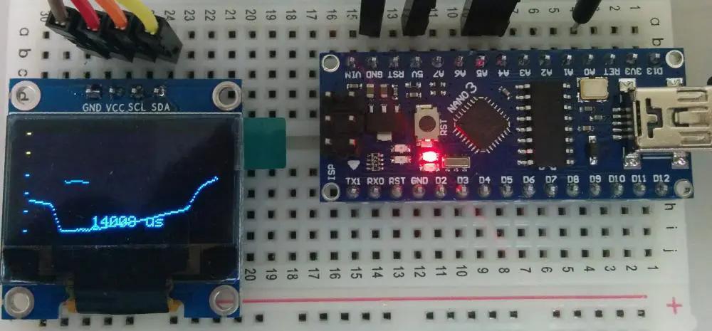
Temperature Sensors

The temperature sensors have become so useful in various industries. Thus, this type of IOT sensors has great influence in our ecosystem. Also, you can observe how refrigerators work. The temperature sensors can easily expose the temperature of such object. It can transmit the degrees at which there is hotness or coldness of an atmospheric condition.

Also, the temperature sensors can calculate volume of heat intensity from any source. Similarly, it can reveal the degrees of temperature modification in an object. Therefore, it alters such modification, converting it to data for future purpose. So, this type of sensor works for agriculture because one needs to control temperature around the farmland.

This type of sensor has at least four groupings. They include the following.

 RTD: This is simply the Resistance Temperature Detectors. Also, this tool can calculate temperature based on modification in resistance. Also, one can observe the film and coil of this device.

Semiconductor: This device reads temperature and is regarded as minute chip. It works as amplifier and oscillator. Interestingly, this tool saves computer memory.

Thermocouple: This tool calculates temperature thereby storing up alterations in voltage. One thing is, its output voltage is influenced by degrees of temperature at such particular time.

Thermistor: This device easily reacts to alterations in temperature. This implies that, it can modify its resistance physically as a result of detection of temperature modification.

Proximity Sensors

Sometimes, proximity sensors are taken as motion sensors. However, they serve varying purposes. So, one can’t conclude they are similar. Furthermore, proximity sensors can calculate and detect any distance from a device. Thus, it doesn’t necessarily have to physically come in contact with any object before proximity sensors can detect distance. They are available in IOT applications.

Proximity sensors can quickly sense mobility and that is why proximity sensor is widely common in any retail sector. Also, proximity sensors are great at detecting close contacts on connected devices. Again, you find proximity sensors common in places such as airports, shopping centers, mortar stores, convenience stores, and stadiums.

Furthermore, proximity sensor is grouped into ultrasonic sensor, capacitive sensors, and inductive sensors. Also, proximity sensors use some photoelectric technicalities to detect nearby contacts. The use of light is important in this case.
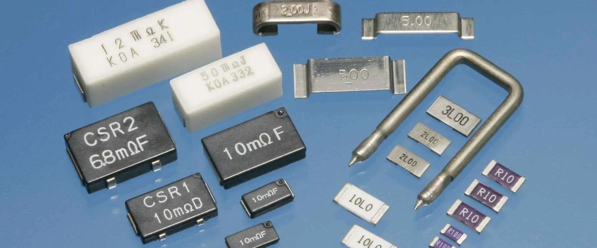
Pressure Sensors

As the name implies, pressure sensors deal with calculating the pressure applicable to any form of sensor. Thereby, pressure sensors can work on atmospheric force. Pressure sensors calculate the volume of pressure that a fluid needs so as not to dilate. Also,  pressure sensors work for industrial apps.

Interestingly, this sensor can calculate weight of an animal because it measures volume of pressure used per unit. Also, pressure sensor is a type of the IOT sensors can detect alterations in fluids which could be gaseous or liquid. As long as the force modifies, this sensor senses such changes. Therefore, it transmits the data to connected devices.

Optical Sensors

This class of sensor works with light conversion. This implies that optical sensors change light to electronic indicator. Today, we have countless use cases where optical sensors are functional. Commonly, optical sensors work for vehicles. This is because optical sensors respond to signals. So, a driver can detect alterations while driving because optical sensors can process any obstacles.

For every smart phone, optical sensors play a vital role in their construction. Battery life relies on light sensor for expansion. For smart cars, optical sensors are useful in them. This is because such cars use optical sensors for detecting factors that may alter motion in vehicles. It easily detects any unfavorable condition on the roadways. So, optical sensors help scan both vehicles and roads regularly.

Concurrently, optical sensors calculate various devices. Optical sensors can surveil electronic device, light, and electricity. So, this makes it functional in healthcare and biomedical.
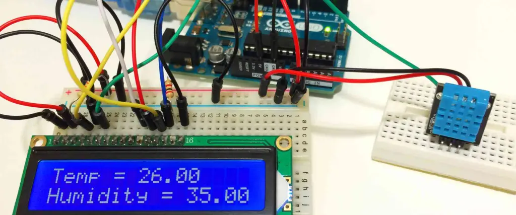
Humidity Sensors

humidity sensor project
Humidity Sensors

Humidity Sensors are instrumental in calculating humidity. Also, if any alterations occur in humidity, the humidity sensors easily indicate. As they are functional in residential area, the humidity sensors also work for industrial purpose.

Over the years, the humidity sensors have been useful in meteorology stations, hospitals, and other industries. Interestingly, it helps calculate volume in relation to water vapor and gases. Furthermore, it works for ventilating as well as heating. Since it measures water vapor, it helps in predicting weather conditions.

Chemical Sensors

There is no doubt that chemical sensors have saved lives. Also, this is because with the aid of chemical sensors, it traces chemical outflow from containers. When this happens, it alerts humans by processing data collected and analysis takes place.

The chemical sensors help manage harmful chemicals that may affect human existence. That is why they are useful in any plant environment. Also, it identifies any contaminations in chemical formation fluids. This sensor greatly impacts our lives because it helps prevent accidents.

Some chemical sensors include chemiresistor, chemical transistor, and electrochemical sensor. Also, this sensor identifies any explosive chemicals in our environment.

Infrared Sensors

These IOT sensors are available in two types. Infrared sensors can either be passive or active sensors.

The passive infrared sensors are common and are available in quantum or thermal types. However, the quantum types work quicker. For the active sensors, it uses photodiode to identify items.

The infrared sensors always have varying degrees of output. Also, this relies on the force of signal it gets. The infrared sensors quickly detect intensity of infrared radiation in the environment. Thus, the infrared sensors can emit this infrared radiation. Additionally, it calculates emission of heat from devices.

For instance, in healthcare, infrared sensors are vital. This is because they can scan blood pressure. Also, televisions can receive signals through infrared sensors. Also, infrared sensors are crucial for viewing concealed layers in works of art such as painting. Furthermore, it detects the authenticity of these paintings and reveals any modifications in them.

Gas Sensors

These types of IOT sensors work for air contamination. This implies that the gas sensors can sense any toxins in air. It helps to maintain a safe and serene environment by monitoring the quality of air around us. Therefore, if there is any alteration in air quality, it immediately receives signal.

For instance, for the mining industry, the gas sensors are important. It helps to detect harmful gasses. Also, an industry such as oil and gas can use gas sensors to detect carbon dioxide and combustible gases. There are common gas sensors and they include hydrogen sensor, hygrometer, oxygen sensor, air pollution sensor, gas detector, and breathalyzer. All these sensors simply help to surveil quality of air, sense changes in it, and identify different gasses.

Smoke Sensor

As its name implies, these types of IOT sensors are specifically made to detect smoke and possible hazard it causes. It identifies any airborne contaminants. No doubt, the smoke sensor is very efficient in this regard.

Smoke can cause toxins in the environment. That is why many manufacturing industries use smoke sensor to detect level of emission of smoke. Smoke sensor monitor fire, flame, and gasses. As a result of this, it reduces the exposure to danger in many hazardous environments. Optical smoke sensor is a common type of smoke sensor.

Level Sensors

These types of IOT sensors help to detect the level of any substance or particles that emanate from any source. Also, these sources may be closed and open sources. It detects level of any liquid that may emanate from different systems.

Importantly, the level sensors are gaining more popularity today. As such, many industries use them. This is to alert them of the level at which substances flow through different sources.

The level sensors can also monitor and gauge fuel levels. Industries producing alcohol use the level sensors to calculate amount of liquid substance they have. Water reservoirs, compressors, and machine devices use level sensors. Note that the purpose of using level sensors is to collect and process available data.
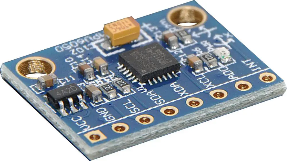
Gyroscope Sensors

Gyroscope sensors can calculate speed. It is a sensor that detects velocity of speed. It is a common type of sensor that automotive uses. For video games, the gyroscope sensors help to calculate the motion sensing. Anything in relation to speed, this sensor works for it.

Gyroscopes are referred to as angular velocity sensors. To trail the motion of a device, the gyroscope sensors apply gravity for this. The various kinds of gyroscope sensors you can find are vibrating structure and rotary.

Noise Sensors

The noise sensors are important sensors because they help to calculate the volume of noise from any device. Also, noise pollution can be controlled with the aid of this sensor.

Thus, this sensor can easily detect noise level. Noise levels can be known these days because of the use of noise sensors. Integrated microphone as part of the noise sensor makes it possible to scan climatic sound. This way, you can easily trace sound and noise levels. Also, you process data gather while generating reports.

Noise sensors are mostly used in environments that produces harmful noise. Construction industry uses noise sensors. Also, these sensors help to scan road traffic. Thus, it helps to research noise hazards on the roads.

Noise sensors are helpful at homes, too. It helps to detect the level of noise pollution around you. Furthermore, certain noise sensors manage noise levels for kids as well as pets.

There are two types of noise sensors. Also, they include geo phone and hydrophone. A geo phone can modify motion from the ground to voltage. It is what geophysicists use in calculating electromotive force from barometer. This is known as seismic activity.

Hydrophone detects and archives sounds, echoes, and noise from underwater. Also, it records every sound gathered from each direction of the underwater. It helps to note the varying degrees of noise from the underwater and process information. Less than a month, one can record deep underwater sounds using the hydrophone.

Magnetic Sensors

These types of IOT sensors are similar to proximity sensors. Also, they may have some slight differences. However, their similarity is in relation to how both sensors can identify the presence of devices. Whether the devices are nearby or distant, proximity sensors can detect it.

For magnetic sensors, electromagnetic radiation is important. This way, they can easily sense objects. Modification that takes place in any magnetic field can be identified by magnetic sensors.

It identifies modification in strength and flux of the field. It responds to modification in the field by giving signals. Also, they can give linear sensing. Furthermore, reed switches are one of the types of magnetic sensors.

Motion Sensors

As its name implies, motion sensors simply identify movements. However, these movements are measured within a specific orbit. Note that, they can give electrical signals when they detect anything including the appearance of somebody.

Motion sensors are mostly in accessible places like public environments. They are in toilet flushes, soap dispensers, doorways, and in many buildings. They are also present in many camera triggers. That is why they can give signals or alerts when there is detection of something. One can see them in apps meant for security purposes.

Water Sensors

We all need quality water that won’t harm us. That is why water sensors are important. The water sensors help to keep water clean and purified. In this way, our general well being is not exposed to water pollution.

Certain parameters are used for measuring water with these sensors. These are temperature, conductivity, salinity, and pH. This way, a lot of conservation takes place around us.

Some conditions of the water are also evaluated. These range from its physical to chemical composition as well as biological condition. Also, note that these sensors can also detect how pure some water bodies are. It includes the rivers as well as lakes. At the end, only quality water will be available for both industrial use and human absorption.

Water sensors can be used in both flowing water and stored ones in tanks or reservoirs. Also, some swimming pools have these sensors in them.

Accelerometers

Accelerometers

Accelerometers are useful sensors because they help to detect the modification in gravity. Sometimes, there are certain modifications that affect gravity. In such occurrences, accelerometers are functional in identifying acceleration. This implies that, in relation to time, the rate at which modification affects the velocity of any item can be measured.

Also, accelerometers can scan through objects to know the change in its gravity. So, it raises alert if there is an alteration in any device. For instance, pedometers use accelerometers. One can also monitor a flight by checking gravity and motion through accelerometers. Therefore, it sends signals when there is a change in its performance. In addition, data processing helps to detect any faults in devices using accelerometers.

Capacitive Sensors

Capacitive sensors are types of IOT sensors that help to identify certain metallic devices. Also, they help in identifying devices that are non-metallic.

Also, some apps are intricate. Therefore, these types of IOT sensors can help track any device irrespective of how simple or complex they are.

What are the Advantages of IOT Sensors?

There are numerous advantages we derive from sensors. In today’s world, data is important. We can all have access to data because of the availability of sensors. Furthermore, different industries rely on sensors for business. Also, in our individual lives, Internet of Things makes things smoother for us. Our gadgets rely on sensors to be functional.

To gather data about our environment, weather conditions, biological composition, chemical substances, we depend on sensors. IOT devices rely on sensors, too.  From our physical world to digital devices, sensors are important.

Humans no longer have to do some activities themselves. Nowadays, with Artificial Intelligence, our world keeps progressing. The truth is, all benefits of sensors can’t be limited. Daily, huge archives of data are processed and humans can analyze information because of sensors. Even with little storage unit, IOT sensors are still operational.

We can now have access to Internet as a result of advancement in IOT. Mining data is possible for many industries. Also, we can now have availability of data for more than one reason.

Frequently Asked Questions

There are some commonly asked questions when it comes to the world of IOT sensors. In this part of the article, let us consider some of these questions. Also, there are possibilities that questions you need answers for will be answered.

Where Can IOT Sensors Be Used?

People get concerned about places IOT devices can be used. Also, it should be noted that IOT don’t need human response to them before they run. IOT can sense anything irrespective of distance.

Farmers use IOT for agricultural purpose. However, the way we all use IOT differ. This is because our needs are different. Also, the use of IOT in biomedical is a bit different from automotive and military. However, there is connection in data processing.

Are there IOT Data?

This is one of the common questions people ask. Devices use IOT data and collect it from various devices. Data can be sent across several devices for analyze because of the IOT sensors. Through wireless medium, data can be collected. It is not a necessity to have power source before IOT can connect to devices.

What do IoT Sensors measure?

IoT Sensors gather huge amount of data about their surroundings. Also, these sensors can measure light, measurement, and air quality. Furthermore, water quality, soil moisture, and motion.

Conclusion

There are different types of IOT sensors in today’s world. Also, it is great that humans can explore these sensors including rain sensors, image sensors, magnetic sensors, infrared sensors, among others. Also, IoT can measure motion, temperature, gravity, sounds, smoke, flame, water, and many other things.

 Furthermore, it sends alert when there is danger. With it, we can sense obstacles that may affect future innovations. So, we are able to proffer quick solutions to such challenge. We hope that you have learnt the importance of IOT to our world.

Top 10 SMD Resistor Manufacturers In The World

SMD Resistor

The evolution of electronics accessories and components is a continuous process resulting from the daily research in the field of technology. In this evolution, both active and passive electronic components are applied. Passive components are such circuit elements as resistors, inductors, capacitors, etc. we have different types of resistors depending on the method of fabrication involved in their manufacture. Some examples of resistors are the wire wound resistor, thin film resistor, thick film resistor, carbon composition resistor, shunt resistors, current sensing shunt resistors, precision shunt resistors, chip resistors, SMD shunt, sampling resistor, DIP shunt resistor, etc.

All resistors are passive elements that perform the same functions in an electrical circuit, no matter their type. Deciding on the type of resistor to use in a design rut depends on the best fit. SMD resistor, for example, is one of the best and most efficient resistors of all time. Different companies deal in the fabrication, development, and supply of these SMD resistors. The following are the top 10 SMD resistor manufacturers in the world.

Antonio Precise Product Manufactory Ltd.

FULL PCB MANUFACTURING Quote

Situated in Hong Kong, the Antonio company mass-produces SMD resistors. It is the leading SMD manufacturer company in the world, having above 1000 employees. The company was established in 2000 and mostly specialized in producing ICs and SMD resistors. Being the leading SMD resistor manufacturer, the company has a total revenue of between 2,000,000 and 5,000,000 US dollars. The company has received such awards as ISO 9001 Quality Management System, ISO 14001 Environmental Management System, Creditable Enterprise Award, and the Trade and Industry Department Quality Award, 2000. Moreover, the company can boast a Bluetooth Qualification Body Award (BBQ) for having fabricated the ATO Bluetooth Headset BT20.

Market

Being the leading SMD manufacturing company, it has a worldwide market. However, most of its strongest market holds are in the Middle East, South America, North America, and South East Asia.

Shanghai Keter Polymer Material Co. Ltd.

Founded in 1997, Shanghai Keter company mostly specializes in the research, improvement, and fabrication of various electric circuit components such as PPTC, PTC fuse, PTC Resettable fuse, SMD resistors, Resettable fuse, etc. With experience spanning 25 years, the company has improved its technology and applied it in the development and production of PPTC worldwide, an additional task over SMD resistor production. Consequently, the company has become one of the leading PPTC suppliers in China.

Qualifications

Shanghai Keter company holds the International Quality Management System ISO9001 certification, and its products have additional UL, TUV, and CCC certifications, having passed the SGS tests and met the ROHS demands.

Products applications

Keter SMD resistors and other components are applied in communication switches, computers, battery sets, distribution frames, micro-electrical machines, ADSL facilities, transformers, and other circuits in electrical appliances and gadgets.

Market size

Keter company has recorded around 1000 customers recently but is working towards increasing the client pyramid by providing high-quality products and availing them to its clients at reasonable prices.

Employees and Revenue

Keter company has between 100 and 500 employees, with revenue of 5,000,000 and 10,000,000 US dollars.

Shenzhen Cao Li Wei Industries Co. Ltd.

Founded in 2000 in China, Shenzhen Cao Li Wei industries Co. Ltd is an electronic company that mainly deals in the Taiwan Yageo electronic components, including SMD resistors, chip beads, SMD inductors, and chip capacitors, etc. Additionally, the company distributes Tantalum diodes, transistors, capacitors, etc. Due to the ability of the company to provide its clients with various choices and services to meet their demands, the company maintains a good reputation as the largest Yageo agent in Southern China. Consequently, the company achieved the authority of attorney of Uni-Ohm Viking and Chilisino. The company also enjoys maximum technological support from Taiwan Yageo and other aspects such as after-sales services, which aids in expanding the market scale of the company.

Administration and market

A mature administration is one of the company’s characteristics. Consequently, its employees, whose population is between 50 and 100, are highly qualified and work effectively towards producing products that are highly efficient, flexible, and of high quality. Moreover, it is possible to sell out the goods at lower but profitable prices and offer them the best sales service, courtesy of the highly trained marketing specialists in the company. An advanced detection system aids in testing the products to ensure they meet the best quality, in line with the high-tech expectations. Customers apply the company’s products in communication systems, home appliances, security systems, digital medical equipment, etc.

Oswell E-Group Limited

Oswell is a China-based SMD resistor-production company founded in the year 2003. It deals with such resistors as shunt resistors, current sensing shunt resistors, precision shunt resistors, chip resistors, SMD shunt, sampling resistors, DIP shunt resistors, etc. Additionally, the Oswell company has 19 years of experience in resistor production, with several qualifications such as the ISO 9001 international quality system certification in 2015 and the IATF 16949 British NQA International Certification body in 2016.

Application of the company’s products

Oswell’s products are applicable in many fields such as automobile designing, electrical appliances, fabrication of smart homes, power supply plants, industrial controllers, energy plants, etc. The company aims to create value with customers globally and win the market by providing reliable, high-quality products.

Market

Being a China-based company, Oswell has its main market as the domestic market, which contributes the better part of its market. However, its products are spreading worldwide, through the Middle East, South East Asia, North America, and South America.

Employees and Revenue

Oswell hosts between 50 and 100 employees, with a staff population of between 10 and 15 members. From the most recent statistics, Oswell has revenue of between 200,000 and 500,000 US dollars.

Filur Electric

Filur is a Ukrainian electronic company founded in 1993 that takes the lead in Ukraine’s Electro-technical production and Radio-electronic components provision. Filur’s headquarters are in Kiev city, with other branches in Dnepropetrovsk city in Ukraine and St. Petersburg district in Russia. The latter has aided in the development of the Russian market since the very first days of Filur’s existence. It focused on producing the best, high-quality products that laid the foundation of the company’s strong market structure. In addition, expanding the range of products assists in widening the product market pyramid.

Main products of the company

Filur electric mainly deals in producing SMD resistors, resistor arrays, precision resistors, trimming resistor capacitors, thermistors, leaded metal-film carbon resistors, etc. The employee population in the company is between 10 and 50 employees, who can raise a total revenue of between 500,000 and 1,000,000 US dollars.

Synthon-Tech Corporation

Founded in 1988, the company has 34 years of components fabrication experience, which helps in producing components of the right quality. Additionally, Synthon Tech company dedicates its productive time to producing passive circuit elements such as capacitors, resistors, and inductors. Synthon Tech is located in Taiwan, but its products are traded worldwide.

Factory and market size

In the domestic market, Synthon Tech contributes 35% of the electronic components produced, whereas, in North America, components produced by Synthon Tech comprise 19% of the total amount. The factory size of Synthon Tech is between 5,000 and 10,000 square meters, with an operations staff of between 5 and 10 people.

Golden King (HK) Tech Limited

GOLDEN KING (HK) tech limited, an electronic component manufacturing company, was founded in 1995. The company is located in Guangzhou, Shenzhen, China, but has its sales markets in several cities across China, such as Shanghai, Chengdu, Beijing, and Hong Kong. Having a 27-year of experience, the company has become one of the best capacitor-producing companies in the world. Golden King Tech mainly deals in such components as SMD resistors, ceramic capacitors, tantalum capacitors, chip resistors, SMD inductors, photocoupling, integrated circuits (IC), etc. Products from Golden King tech company are of high quality and are available at reasonably affordable prices all over the world.

Market

Golden King tech company mostly exports its products to Southeast Asia, North America, East Asia, the Middle East, South America, and many other countries worldwide. Additionally, the market size of the company’s products continues to expand daily, following the better range of products and services the company offers to its customers. However, the company is still making efforts toward expanding its customer base.

Employees and Revenue

The company hosts an employee population of between 50 and 100, recording a total revenue of between 100,000 and 500,000 US dollars.

Shenzhen E-Best Industrial Co. Limited

Founded in 1981, Shenzhen e-best company has been the leading fabricator and supplier of SMD resistors and some other various components such as vehicular laser, switching power supply, ICS, inductor, capacitor, Arduino zone, GPS module, burning machine, Infrared sensor/emitter, IC, thermistor, resistor, SMD resistor, M/A-COM, diodes, transistors, crystal, fuse, IGBT, fiber optic receiver, relay, DVD laser head, test needle/probe, dip tantalum capacitor, switches, etc. Shenzhen e-best company has its headquarters in FuTian District, Shenzhen, China, with its operational factory in Mainland China.

Market

Shenzhen e-best company sells its products worldwide, in overseas markets such as Korea, Singapore, the USA, Germany, etc. Additionally, the company deals in a wide range of products. It avails them to clients at affordable and reasonable prices within a short period since the placement of the order by the client. Consequently, it assured of a market advantage over similar companies dealing in producing SMD resistors and other components.

Employees and Revenue

Shenzhen e-best company hosts a relatively smaller employee population compared to other similar companies as it has between 5 and 10 employees. Still, it produces many products following the advanced technology present in the company. Moreover, the company has recorded a revenue of between 500,000 and 1,000,000 US dollars in recent statistics.

Shenzhen Heketai Technology Co. Ltd.

Founded in 1992, Heketai tech company is a competent electronic component production enterprise dealing in the fabrication, development, and distribution of such products as SMD resistors, SMD diodes, SMD ceramic capacitors, SMD transistors, etc. HKT is an independent brand owned by Heketai tech company. Additionally, Heketai tech company mainly focuses on producing Lead-free environmental products. Heketai tech company has its headquarters located in Guangdong, Shenzhen, China.

Certification

Heketai tech company has the International Quality Management System ISO9001, with all HKT products meeting the environmental protection standard RoHS. Heketai tech also holds other titles such as

  • China’s best-selling brand
  • Civilization corporation
  • Chinese electronic enterprise most potential brand
  • Chinese Famous brand

Market

Heketai tech distributes its products worldwide. And mostly in the Middle East, Eastern Asia, South East Asia, Northern America, and South America.

Employees and Revenue

Heketai tech company hosts an employee population of between 50 and 100 employees and has had a revenue of between 1,000,000 and 2,000,000 US dollars in the recent past.

Shenzhen Xin Bai Chang Technology Co. Ltd.

Established in 2005, Shenzhen Xin tech is an electronic component manufacturer and supplier located in Guangdong, Mainland China. Shenzhen Xin tech company mostly deals in such products like:

  • connecting sockets
  • power relays
  • potentiometers
  • SMT inductors
  • SMD LEDs
  • film capacitors
  • SMD electrolytic capacitors
  • SMT transistors
  • ceramic capacitors
  • SMD capacitor diodes
  • SMD/chip resistors
  • IGBT module
  • transistor integrated circuit components and much more

With 17 years of experience, Shenzhen Xin tech company produces high-quality, reliable products.

Certification

The company bears authorization from three national authoritative departments, with the products certified by ISO9000, RoHS, and CE systems.

Market

Shenzhen Xin tech company has its main market as the domestic market in China. Central America constitutes 10% of the company’s market. The Middle East contributes 20% of the company’s market.

Employees and Revenue

Shenzhen Xin tech company has an average of 5 โ€“ 10 staff members, with an employee population between 10 and 50. From the most recent statistics, Shenzhen Xin tech company has a revenue of 200,000 and 500,000 US dollars.

Conclusion

The lack of SMD resistors should not stop you from performing research and design tasks. The above information makes it possible to understand the top 10 best SMD production companies worldwide. The companies deal in the fabrication, production, and distribution of SMD resistors.

Estimating the size of the company can be easier from the details above. However, the number of employees is not necessarily proportional to the company’s size. Most of these companies have greatly incorporated technology in the fabrication and production of these SMD resistors.

Who are the Leading Electrical Coil Manufacturers?

Electrical Coil Manufacturers

Electrical coils can be described as an electrical conductor. This is usually wound to form a coil, a spiral, or a helix shape. They have a major function, which is the transmission of electricity, heat, or sound.

Furthermore, the electrical coils are also called electromagnetic or magnetic coils. This terminology could cause some form of confusion. This is because the word electromagnet could specifically have to do with electric coils. These coils directly affect any external object via a magnetic field.

How Do Electrical Coils Work?

Although electrical coils serve in many different applications, the majority of electric coils usually share similar electromechanical principles and basic construction.

Furthermore, the electrical coils come to be whenever a specific conductive metal wire is wired around a specific insulator. The whole wire is called the winding, then each of the individual loops present in that winding is called a turn. Also, there is a hole in the coilโ€™s center. We refer to this region as the magnetic axis or core area. Same way, both ends of this wrapped wire are usually changed into different terminals for electrical connection referred to as โ€œtaps.โ€

Furthermore, the creation of power happens whenever there is a link of the taps to a specific electric current that moves via coiled wires and then magnetizes the coil.

This can happen due to the fact that the electric currents flowing creates a form of circular magnetic field. This is present along the entire conductorโ€™s length. Also, the coiled electric conductors help in creating a stronger magnetic force compared to the straight conductors.

This is because they manufacture similar or the same magnetic fields that merge at the loopโ€™s center. Also, the electrical coils that are made up of many electric loops which are wound round that same axis, could yield magnetic fields that are very strong.

What are the Electrical Coil Materials?

Electric Coil

Although lots of conductive metals exist, Copper and aluminum are most frequently used in making electrical coils. Also, these Electrical coils mainly for heating purposes are usually made up of an iron or nickel alloy. Regarding the insulator, you can manufacture it from some non-conductive and diverse materials, which includes air, cardboard, enamel, or plastic.

Furthermore, the insulation of coils are usually done specially; this is majorly to help in preventing the flow of current between the coil turns as well as shielding the coil from long exposure to any corrosion as well as damage-causing conditions such as vibration, oil, moisture, or salt. You can protect your coils in different ways:

First is encapsulation, and this applies just to the coilsโ€™ wire. The encapsulated coils are also made up of wire, which is already covered in a specific polymer epoxy. Also, the molded coils have plastic coverings, which seals both the wires and the whole winding.

Who are the Leading Electrical Coil Manufacturers?

FULL PCB MANUFACTURING Quote

Sag Harbor Industries, Inc.

Sag Harbor Industries, Inc. are known to have engineers with great craftsmanship. The products here are usually manufactured in the United States. Also they have made a promise to ensure that the items are usually created from high-quality resources. Furthermore, they have efficient and unique electrical coils.

Classic Coil Company

The Classic Coil Company was founded back in 1973 and they offer contract manufacturing of different electronic coils for different industries; winding the wire gauges from about 4-58 AWG

Also, the company is DFARS Compliant, ITAR registered, and ISO 9001-2015 certified. Furthermore, they are one of the best known electrical coil manufacturers and their engineering services makes it possible for them to offer assistance with cost reduction, designing, as well as increase the efficiency of production. You can learn more about the capabilities of the Classic Coil Company by calling or visiting their website.

Quality Coils, Inc.

The Quality Coils, Inc. is ISO 9001:2015 certified. They are one of the best known electrical coil manufacturers internationally for the manufacturing of high-quality electromagnetic coils. In addition, the companyโ€™s goal is offering high-quality products, commits to quick and speedy delivery, as well as competitive pricing. Also, the company understands that all applications are unique, this is why they encourage clients to contact them so as to discuss their specific requirements. Quality Coils, Inc. has over 50 years of professional experience in this field, so they have a lot to offer.

Torelco LLC

Torelco LLC has been existing since 1962, and has been supplying transformers and electric coils of great and superior quality. Furthermore, the company provides solenoid coils, custom coils, toroid wound coils, and ferrite core coils to serve different industries. In addition, Torelco LLC serves different markets including electronics, medical, industrial, and military. If you decide to work with Torelco LLC, you can be sure of them building the same specifications you requested for, as well as need customersโ€™ custom needs.

Precision Econowind, Inc.

Precision Econowind, Inc. is known as one of the major electrical coil manufacturers that comes at very reasonable prices, as well as quick delivery. Also, Precision Econowind, Inc. has been serving the coil industry for more than three decades, and they have vast experience in the production of medical industry coils, loudspeaker, as well as coils that are wound on the tooling/bobbins of customers. They also deal in flat wire, freestanding, edge wound, rectangle, square, and shaped coils. All you need to do is to submit your preferred specs.

Triad Magnetics

Triad Magnetics is known in the electrical coils industry, having been involved for more than 75 years. Furthermore, they are one of the best known electrical coil manufacturers that delivers the best expertise and knowledge in the whole industry. Also present are different inductors and electric coils coupled with their ability to engineer as well as manufacture electrical coils in order to meet the needs of customers. They have met the needs of so many industries for over fifty years and the company has the strong belief that its experience will make the difference.

Johnson Electric Coil Company

This Company is one of the family-owned electrical coil manufacturers, which deals in custom inductors, coils, and transformers. They manufacture three phase isolation and single phase chokes and inductors. Also, they are involved in the careful designing of products so as to meet the right specifications of the customer.

Conclusion

These are our best electrical coil manufacturers. They are involved in manufacturing high quality electrical coils and ensure timely deliveries.