
RAYPCB · ENGINEERING GUIDE
TATSUTA Shielding Film for FPC: Specify the Grade and Grounding
TATSUTA shielding film is a material choice for a defined flexible-circuit construction, not a complete PCB laminate specification. The exact film grade, permanent layers, grounding interface and qualified processing need to be identified before the material can be meaningfully compared or quoted.
This page focuses on procurement and integration of the selected material. It does not assign one thickness, attenuation value or process window to every TATSUTA product, and it does not imply a supplier authorization or certification held by RAYPCB.
State the material function precisely
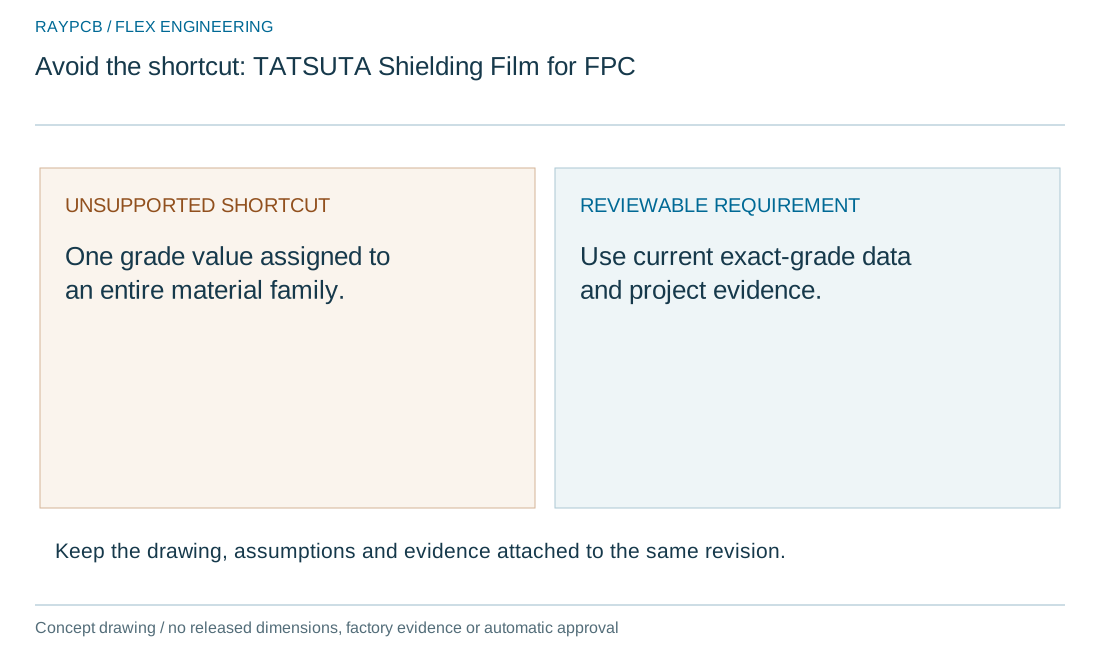
Identify whether the requirement concerns shielding film, a conductive bonding film or another named product. Those roles are not interchangeable. TATSUTA's official material information distinguishes these product categories; use the current exact-grade documentation for technical values.
Describe the circuit region and required connection function alongside the brand name. A purchasing line that says only TATSUTA material leaves the construction and verification ambiguous.
Match the grade to the installed stack
Record permanent thickness, supplied form and any removable liner. Include the relevant underlying coverlay, copper and bonding interface. Determine which dimensions and properties are specified for incoming material and which must be established after integration.
Use FPC EMI-film selection for the local thickness budget. A catalog material value is not automatically the finished installed dimension at a pressed or reinforced region.
| Review item | What to establish |
|---|---|
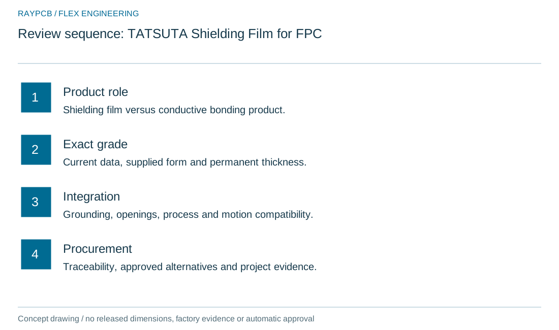
| Product role | Shielding film versus conductive bonding product. |
| Exact grade | Current data, supplied form and permanent thickness. |
| Integration | Grounding, openings, process and motion compatibility. |
| Procurement | Traceability, approved alternatives and project evidence. |
Define grounding and openings in the drawing
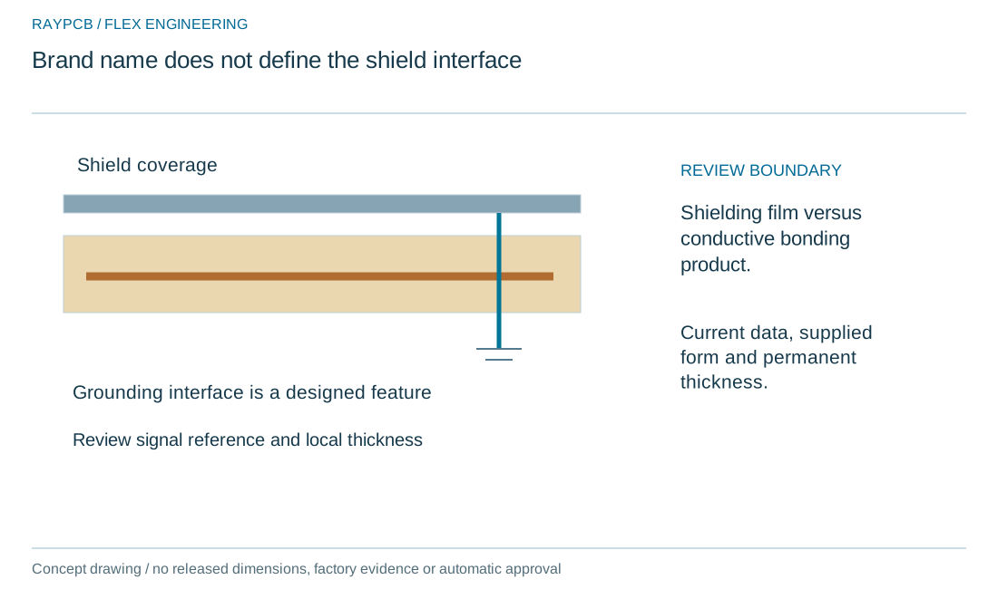
Show the grounding locations, interface geometry, coverage and exclusions. Agree how the resulting connection will be inspected or measured. The material name alone does not establish a usable electrical connection to the circuit.
For the system-level question use flex PCB EMI shielding. A supplier's material test cannot be converted directly into a guaranteed emissions or immunity improvement for an unspecified assembly.

Review processing and motion compatibility
Use the selected grade's current guidance and the manufacturer's qualified construction process. Include lamination, subsequent assembly and rework exposure. Review shield edges and bonding transitions in relation to the installed route and any intended movement.
If the grade changes, assess the effect on thickness, bonding, electrical environment and mechanical evidence. A change within one brand family is still a material change that may need engineering review.
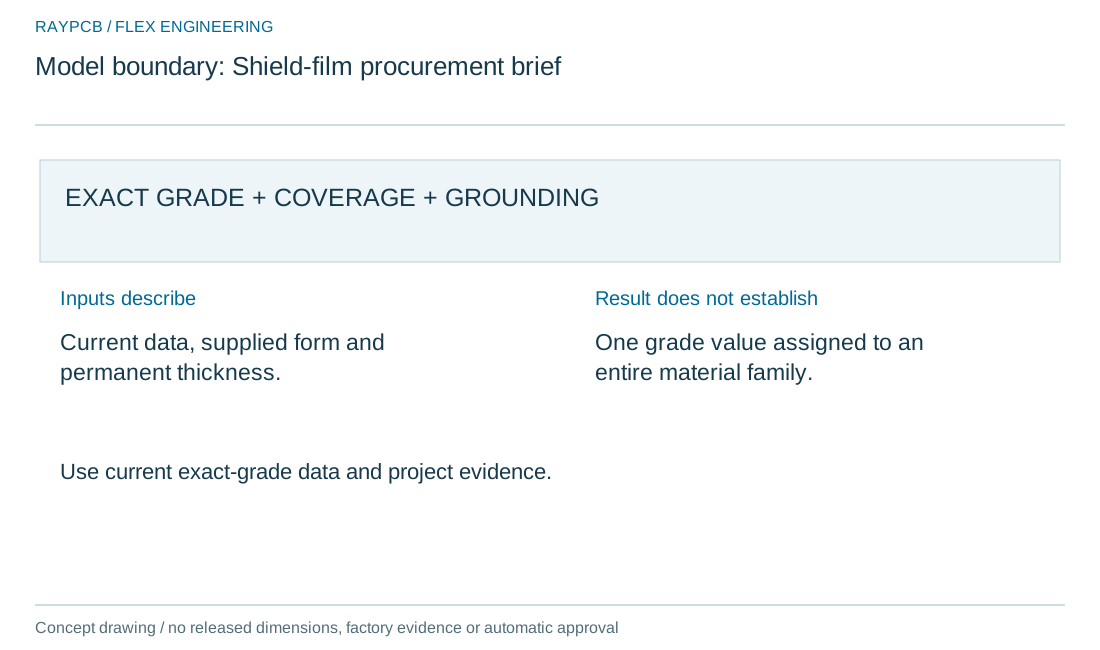
Shield-film procurement brief
Shield-film procurement brief
Use the current inputs and keep the assumptions
Choose the engineering question before entering data. Every field begins blank. Load example provides teaching values so you can inspect the calculation or workflow; it is not a recommendation for dimensions, materials, operating conditions or prices. The example label remains visible after editing. Reset the worksheet before preparing a record based entirely on your own project inputs.
Keep the units and measurement boundaries consistent. A finished thickness is different from an incoming film thickness; a complete current loop is different from one conductor; a bulk dielectric constant is different from effective permittivity. Identify the source and conditions of the values you enter. If information is missing, record it as an engineering question instead of selecting an attractive assumption.
Read the result together with its limitations. A positive geometric margin addresses only the dimensions entered. An evidence checklist records your statements without checking the underlying documents. A cost scenario adds your allowances without supplying current market prices. None of these tools approves a material substitution, predicts service life or issues a manufacturing quotation.
Editing an input invalidates the current result and disables its download until you run the worksheet again. The text download contains the inputs, results and stated limitations. Processing stays in this browser; the tool does not read CAD, upload project files or send your inputs to analytics. No parameters are automatically passed to Contact. Download and attach the record manually if useful, or contact RAYPCB directly without using the tool.
| Input | What to establish before using it |
|---|---|
| Review reference | Use a nonconfidential revision or scope reference. |
| Exact film grade and current datasheet | Self-reported documentation; keep the supporting record or N/A rationale. |
| Grounding interface and coverlay openings | Self-reported documentation; keep the supporting record or N/A rationale. |
| Permanent thickness / finish / adhesion | Self-reported documentation; keep the supporting record or N/A rationale. |
| Lamination and assembly compatibility | Self-reported documentation; keep the supporting record or N/A rationale. |
| Agreed film and assembly verification | Self-reported documentation; keep the supporting record or N/A rationale. |
| Next action / record reference | Nonconfidential reference only; the tool does not verify evidence. |
Optional cost comparison from your own allowances
Use a quotation or a clearly labeled internal assumption for each input. Keep the quantity, construction and inspection scope the same when comparing alternatives. This uncalibrated planning model adds entered values; it contains no current market rates and does not issue a RAYPCB quotation. You can contact the team without completing it.
Entered construction budget
Keep procurement evidence with the part revision
Specify required traceability, acceptable alternatives and the documentation expected with supply. Confirm availability and the actual proposed grade during quotation. Do not assume that a brand page means every grade is stocked or that a particular supply relationship exists.
Retain the material decision with the released circuit stack and the relevant verification. Brand recognition supports identification; it does not replace project-specific construction evidence.
Example: an alternative film with a similar headline property
An illustrative proposal offers a different grade with a similar published shielding figure. The grounding interface, thickness or processing conditions may differ. Comparing the headline figure alone can miss the changes that determine integration.
Create a controlled comparison showing fixed requirements, changed features and the tests needed to resolve equivalence. Leave the alternative unapproved until the responsible engineering review is complete.
Send a grade-specific material request
Provide the exact grade or required function, current datasheet, coverage and grounding drawing, underlying stack, installed geometry and quantity. Identify the expected verification and any permitted alternatives.
The optional budget sums your entered film-integration and validation allowances. For the build route continue to flexible PCB manufacturing; no current material price or universal performance promise is supplied here.
Connect film selection to system evidence
Separate the material question from the system question. The material review identifies the exact film, permanent stack, bonding and grounding interface. The system review identifies the noise source, coupling path, receiver and measurement configuration. Both are necessary when a shielding change is intended to solve a product-level problem.
Map the shield coverage onto the actual circuit outline and installed route. Mark openings, seams, grounding features and regions where the film must be absent. The electrical connection to ground is a designed interface, not a property automatically supplied by the film's brand name or visual appearance.
Add the permanent film layers to the local stack. Review the difference between incoming material values and finished bonded dimensions. Include the effect on a moving region, connector approach or constrained enclosure space. A small additional thickness can matter when it changes a transition or an already tight tolerance envelope.
Review the field and return-path implications. A conductive layer near signals can affect the electromagnetic structure, while its real grounding and material behavior may differ from an ideal reference plane. Revisit the relevant impedance or channel analysis instead of assuming a successful EMI material test leaves the circuit electrically unchanged.
Keep measurements comparable. Record operating conditions, geometry, instruments and the configuration before and after a change. Material attenuation data, local diagnostic observations and product emissions or immunity results have different boundaries. Do not express one as a guaranteed substitute for another.
Qualify the physical integration. Exact surfaces, lamination, later assembly exposure and movement can influence bonding and connection integrity. Preserve material grade, lot and process configuration with the evidence. A substitute within the same product family can still change the construction in ways that need review.
For a supplier discussion, provide the proposed film or required function, coverage and grounding drawings, underlying stack, installed conditions and desired verification. Identify whether the uncertainty is material availability, manufacturability or system behavior. This focuses the enquiry and prevents a generic shielding promise from replacing a defined engineering requirement.
Standards, source context and limits
Use references within their stated scope. Official material documentation applies to the identified grade, conditions and revision. A supplier specimen test is not a guaranteed result for a different finished circuit. Connector drawings govern the specified parts; public category descriptions do not replace them.
Agree the applicable controlled standards, revisions, construction requirements and acceptance criteria for the order. IPC-2223 concerns flexible-board design; IPC-6013 concerns qualification and performance of flexible and rigid-flex printed boards. Assembly workmanship and product-level electrical or safety requirements are separate. A standards reference does not establish a RAYPCB certification or prove that a particular test is included.
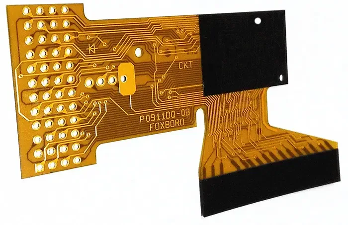
Archive photographs provide visual context from the existing website. They do not establish the precise material grade, present equipment ownership or results of your project. Original diagrams are explanatory construction and review illustrations, not released fabrication drawings or inspection evidence.
For fabrication scope and the agreed construction requirements, see PCB manufacturing.