Important Types and Principle of 2.4K Resistor

100K-Resistor

A 2.4k resistor is an electronic component with a resistance value of 2.4 kilo-ohms. It is a type of fixed resistor. It means that its resistance value is not adjustable. Engineers make it of a carbon film or metal film deposited onto a ceramic or plastic substrate.

2.4k resistors, like other resistors, are useful in electronic circuits to limit current, divide voltages, and provide biasing voltages. They are applicable in audio and amplifier circuits, as well as in digital circuits for pull-up and pull-down resistors. The resistance value of 2.4k is also useful in voltage divider circuits to provide a specific voltage output.

The physical size of a 2.4k resistor depends on its power rating, with higher wattage resistors being physically larger. They typically have color-coded bands or markings that indicate their resistance value and tolerance.

How does a 2.4K Resistor Work?

Resistor Wattage

When you apply a voltage across a 2.4K resistor, it creates an electric field within the resistor that opposes the flow of current through the resistor. This opposition is known as resistance, and it is what makes the resistor useful in electronic circuits. The amount of resistance provided by the resistor depends on its value, which is determined by the material and geometry of the resistor.

In a simple circuit, you can use a 2.4K resistor to limit the amount of current that flows through a particular part of the circuit. For example, if you connect a light-emitting diode (LED) to a voltage source, it can draw too much current and burn out quickly. By adding a 2.4K resistor in series with the LED, the amount of current flowing through the LED restricts to a safe level.

In more complex circuits, 2.4K resistors work in a variety of ways to control the behavior of the circuit. For example, they can be helpful in voltage dividers, current limiters, and biasing circuits.

What Are the Different Types of 2.4K Resistors and How Do They Differ From Each Other?

There are several types of resistors that can have a resistance value of 2.4K ohms. Here are some of the most common types and how they differ from each other:

ยท Carbon Film Resistor

This is a type of resistor that has a thin layer of carbon film deposited on a ceramic or fiberglass substrate. Carbon film resistors are inexpensive and have a high tolerance. However, they are not as precise as some other types of resistors.

ยท Metal Film Resistor

This is a type of resistor that has a thin layer of metal film deposited on a ceramic or fiberglass substrate. Metal film resistors are more precise and stable than carbon film resistors; however, they are also more expensive.

ยท Wirewound Resistor

FULL PCB MANUFACTURING Quote

This is a type of resistor that is made by winding a wire around a ceramic or fiberglass core. Wirewound resistors have a very low tolerance and can handle high power levels, but they are also more expensive than other types of resistors.

ยท Thick Film Resistor

This is a type of resistor that has a thick layer of resistive material deposited on a ceramic substrate. Thick film resistors are relatively inexpensive and available in a wide range of resistance values. However, they may not be as precise as some other types of resistors.

ยท Thin Film Resistor

This is a type of resistor that has a thin layer of resistive material deposited on a ceramic or silicon substrate. Thin film resistors are very precise and stable, but they are also more expensive than other types of resistors.

ยท SMD Resistor:

This is a type of resistor that is mounted directly onto a printed circuit board (PCB). SMD resistors can be made in various types, such as carbon film, metal film, and thick film, but they are generally smaller in size than through-hole resistors and can be more difficult to handle and replace.

The choice of resistor type depends on the specific requirements of the circuit and the application. Factors such as precision, stability, power handling, and cost can all influence the selection of a particular resistor type.

The Method of Making a 2.4K Resistor

A 2.4k resistor is typically made from a ceramic or metal film resistor element. The resistor element contains a thin film of conductive material, such as carbon or metal, which provides the desired resistance value. Engineers put the resistor element in a cylindrical or rectangular body made from an insulating material, such as ceramic.

To create a 2.4k resistor, you must calculate the thickness and length of the resistive film are to achieve the desired resistance value. The resistive film deposits onto the ceramic or metal substrate through a process called thin-film deposition. It involves depositing a thin layer of material onto the substrate using techniques such as sputtering or evaporation.

After the resistive film is deposited, the resistor is trimmed to the exact resistance value using a laser trimming process. This involves using a laser to cut or remove a small portion of the resistive film to achieve the desired resistance value. The resistor is then coated with a protective layer to prevent damage from moisture or other environmental factors.

Finally, the resistor is tested to ensure it meets the desired specifications for resistance value, tolerance, and power rating. This testing typically involves measuring the resistance value of the resistor using a high-precision multimeter or automated testing equipment.

Conclusion

In conclusion, 2.4K resistors are useful in a wide range of electronic circuits due to their specific resistance value of 2.4 kilohms. Moreover, they work as voltage dividers, current limiters, and pull-up or pull-down resistors. Additionally, their small size, low cost, and reliability make them ideal for use in a variety of applications.

One of the key advantages of 2.4K resistors is their versatility. Specifically, they can serve a lot in a wide range of electronic circuits from simple LED circuits to more complex circuits. Furthermore, the process of manufacturing 2.4K resistors involves the deposition of a resistive film onto a substrate, followed by laser trimming and protective coating. As a result, this precise and controlled manufacturing process ensures that the final product meets the desired specifications for resistance value, tolerance, and power rating.

Overall, 2.4K resistors are an essential component in many electronic circuits, offering versatility, availability, and reliability. Whether used as voltage dividers, current limiters, or pull-up resistors, their specific resistance value makes them an important tool for electronic design and experimentation.

What are the Components, Applications, and Operations of Light Sensors?

light sensor

Light sensors appear to be quite simple. They detect light in the same way as a thermometer detects temperature and the speedometer detects speed. We perceive speed and temperature in a straightforward manner, making them simple concepts. Yet light is incredibly intricate. As speed and temperature are intense qualities, they are independent of an object’s size or mass.

Light could be measured either extensively by dividing it by its area, in which case the amount of light collected determines the collector’s size (for example, a huge solar array gathers more light compared to a little solar charging cable). So what exactly do light sensors do? Before attempting to grasp what light sensors are, it’s crucial to understand the units.

What are the Units of Light Sensors?

light sensors

We must have the ability of quantifying light in order to fully comprehend light sensors coupled with how to utilize them. Regrettably, there are some odd units used to measure light. For instance, whereas light sensors commonly measure light in lux, lightbulbs are typically rated utilizing lumens. Moreover, the candela is a mysterious base unit that serves as the foundation for both lux and lumens.

The Candela

The measurement is used to express the strength of light as it appears to the human eye, or luminous intensity. It really is established on the official SI formula that assigns a weight to each light wavelength inside a beam according to how sensitive it is to human eye. The human eyes are more sensitive when a light’s luminous intensity is higher.

Because the brightness of the beam depends on both the bulb’s output and the amount of output which is focused in a certain direction, candelas are not suitable for comparing flashlights and lightbulbs. The majority of flashlights utilize mirrors to focus more light inside this output direction, making them appear brighter. That means that despite employing the same power consumption and outputting the same overall quantity of light, the bulb’s intensity has grown in that direction. We require a brand-new unit, the lumen, in order to accurately quantify a bulb’s output.

Lumen

The entire luminous flux that related to the light bulb is measured in lumens. This represents the result of a solid angle which the beam will fill (measured in steradians) and the luminance intensity (measured in candelas).

When the whole 4ฯ€ steradians are multiplied by a luminous intensity equaling 10 candelas, that comes from a bulb that emits light from all directions, the result is a 126 lumens luminous flux. Similar to the inside of a flashlight, the mirror solely on a single side of a bulb would reflect half of its output, making its other side to appear brighter.

This solid angle will only be 2ฯ€ steradians, but the light’s intensity would increase to a value of 20 candelas. Even after multiplying the light’s intensity from the mirror’s opposite and newly designed angle, a luminous flux of 126 lumens would still be produced. Regardless of the way in which the reflection of light takes place, the bulb would produce a luminous flux of 126 lumens.

Lux

Why would light sensors need to utilize a separate unit when light bulbs were rated in lumens? Because of it, musicians don’t get blind during performances. When held inches from the eyes of Drake, one flashlight may appear to be blinding, however some phone flashlights aimed at a stage isn’t quite as bright.

Only a limited quantity of light reaches his eyes while on stage since it disperses as it exits the phone. This quantity of light which an object gets decreases with distance from its source. A unit termed lux, which is equivalent to a lumen for every square meter, is used in measuring illuminance, as well as the light that is perceived by the surface.

The sheet’s area as well as the light intensity are both constant, but when more of this solid angle gets occupied, the sheets receive more illumination. Because they are unable to determine whatever solid angle they will be in, light sensors must measure illuminance, which is the amount of light that is cast over the unit area.

What are the Uses of Light Sensors?

FULL PCB MANUFACTURING Quote

Position Detection

Illuminance, which is measured by light sensors, is a more versatile quantity than light source brightness. This light sensor may be employed to determine relative distance to the source since this illuminance diminishes as that sensor travels away from a constant light.

As light sensors typically have a flat, as well as a one-sided surface, the solid angle that the sensor occupies when viewed from a source of light may alter with respect to its orientation. This light sensor is filling the maximum solid angle it can by being perpendicular towards the light’s direction.

While facing away or parallel to such light beams, this light sensor eventually senses no direct illumination. As this light sensor spins away from light, the solid angle lowers and the illumination correspondingly diminishes.

Brightness Management

There are several uses for light sensors. The most typical applications in our everyday lives are on tablets and cell phones. Nowadays, the majority of portable personal gadgets have light sensors for brightness adjustment. In order to conserve power and avoid shocking the user including an overly bright screen, the device lowers its screen brightness whenever it detects that it has now gotten into a dark environment.

Using light sensors to manage the automated lights in cars and streetlamps is another typical application. The little inconvenience of turning the lights on is avoided by using the light sensor for activating a bulb whenever it gets dark outside, and power is conserved during the daytime whenever the sun gets bright sufficiently.

Security

Yet, there are a lot more applications besides consumer convenience. The security application of detecting infiltration into rooms or containers is crucial. Knowing whenever the shipping container is opened might be crucial when transporting expensive cargo since it helps with the resolution of cases concerning product loss. It is possible to establish when robbers plundered the container by using a less expensive photo-resistor to record each time it is opened.

Many other products are light sensitive, but only light sensors can provide accurate information about light. For instance, exposure to sunshine can harm older pieces of art, paintings, as well as photographs printed on paper, therefore it’s crucial to know the quantity of light they receive. The light sensor can be employed to check that a piece of artwork wasn’t exposed to sun for an excessive amount of time before delivery.

Planning

The art can also be permanently installed using the light sensor. The light sensor can be utilized to locate paintings in areas of the museum that aren’t too bright for certain materials like those close to the windows or entrance.

This process is comparable to how solar panels are placed on houses or in the fields. The light sensor can be utilized to determine the ideal location with the greatest direct sunlight because it is pointless to construct as well as install the solar panel inside a location that won’t receive sufficient direct sun.

Agriculture

Agriculture is impacted significantly by sunlight, particularly in the American West where there is a lack of water. Knowing which areas of the land receive the most sunlight is crucial since different crops have varying light requirements. Farmers are under a moral and financial imperative to restrict water use to a minimum while yet ensuring the hydration of their crops as the water supply in regions like Utah grows more constrained.

In order to prevent the scorching sun from burning off of the water even before plants and soil can adequately absorb it, one strategy being used is to give the crops some water in the evening or around afternoon. The sprinkler system might be automatically controlled by the light sensor, watering whenever the sunshine wasn’t at the brightest.

How Does a Light Sensor Work?

We can begin to comprehend how illuminance gets measured utilizing light sensors knowing that you will be familiar with the confusing range of units used to define light.

Photodiode

Illuminance is occasionally measured by light sensors using a part known as a photodiode. Light beams have a propensity to knock free electrons inside photodiodes, which results in the flow of electric current. The strength of electric current increases with light intensity.

The light’s illuminance could then be determined by measuring the current. When the term electric current that is light induced sounds familiar, that’s because it describes how solar panels work to power houses and road signs. In essence, a solar panel seems to be a very large photodiode light sensor.

Photo-resistor

The photo-resistor is another light sensor type. This photo-resistor can be described as a light-dependent resistor, which means that if the intensity of light shining on it changes, so will the resistance.

Conclusion

As explained above, light sensors detect light in the same way as a thermometer detects temperature and the speedometer detects speed.

Properties, Advantages, and Applications of High Voltage Ceramic Capacitors

High Voltage Ceramic Capacitors

Capacitors are crucial components in any electronic device. These components store electrical charge temporarily. Capacitors are available in different types and sizes. The development and advancement of technology has helped to achieve great success in the development of high-voltage ceramic capacitors.

In recent years, these capacitors have become an indispensable component widely used in high voltage and high power electronic devices. Therefore, they are widely known in the electronics manufacturing industry. ย The focus here is on high voltage ceramic capacitors.

What are Ceramic Capacitors?

A ceramic capacitorโ€™s dielectric is made of a ceramic material. Ceramic was initially used in producing capacitors before other materials were used. To data, ceramic is still being used to produce capacitors since it is a good insulator. Ceramic capacitors comprise several geometries which include barrier layer capacitors and ceramic tubular capacitors. However, these capacitors are now obsolete because of their electrical characteristics and size.

The multi-layer ceramic capacitor is commonly integrated in modern electronics. It is also known as ceramic multi-layer chip capacitor (MLCC). This capacitor is the usually produced in large quantities. About 1000 billion of it is produced yearly. Also, MLCC is manufactured as surface mounted devices and is widely integrated in electronic devices because of its small size.

Furthermore, ceramic capacitors have small capacitance values which are usually between 1nF and 1ยตF. However, there can be capacitance values of about 100ยตF. Ceramic capacitors usually have low maximum rated voltage. However, there are some high voltage ceramic capacitors. Ceramic capacitors can connect safely to an AC source.

Furthermore, these capacitors feature a high frequency response because of their low parasitic effects like inductance or resistance.

What are High Voltage Ceramic Capacitors?

Ceramic capacitors can be designed in such a way they can withstand higher voltage. These are high voltage ceramic capacitors. They can withstand voltages within the range of 2Kv and about 100Kv.

High voltage ceramic capacitors comprise high dielectric materials and as such, they feature great volumetric efficiency. These capacitors are usually classified as Class 2 types. They are widely integrated in various applications like electricity distribution networks and therapy power supplies. A particular material solution known as K1700 is integrated in high energy pulse power applications like Pulsed High Voltage Generators.

High voltage ceramic capacitors donโ€™t feature low dissipation factors. Also, they donโ€™t have the stability voltage and temperature featured by Class 1 capacitors. It is important to know that the capacitance will drop for many of these materials. Furthermore, the ageing rate is usually quoted as 0 percent for every 10 hours.

High voltage ceramic capacitors are ideal for use in power circuit breakers, high voltage laser power, and induction furnaces among other. Also, these capacitors can withstand high voltage and they have disc-like shape. These capacitors remove high-frequency interferences. Therefore they are ideal for use in negative ion products like X-ray machines, igniters, power equipment, and X-ray machines.

Properties of High Voltage Ceramic Capacitors

FULL PCB MANUFACTURING Quote

Precision and tolerances

Ceramic capacitors are in two classes, which are Class 1 and Class 2. Class 2 capacitors are high voltage ceramic capacitors. They feature a high capacitance for each volume. Also, these capacitors are widely integrated in applications that are less sensitive. Also, the thermal stability of these capacitors is usually +-15% in operating temperature range.

On the other hand, Class 1 capacitors have a stable capacitance value in terms of applied voltage, frequency, and temperature.  Also, these capacitors are very accurate.

High voltage and high power

Larger ceramic capacitors can tolerate very high voltages and these are known as power ceramic capacitors. These capacitors are usually higher than the common ones integrated on circuit boards. Also, they feature specialized terminals that ensure safe connection to voltage supply. Furthermore, power ceramic capacitors can tolerate voltages within the range of 2kV and 100kV.

Size advantages

When there is a need for high packing densities, MLCC devices have a better advantage than other capacitors. For instance, the โ€œ0402 MLCC package usually measures about 0.4mm x 0.2mm. There are more metal and ceramic layers in this kind of package.

Advantages of High Voltage Ceramic Capacitors

Smaller capacity

High voltage ceramic capacitors are beneficial in several applications. These capacitors are capable of achieving small capacity. The smallest capacity of regular film capacitors is 0.1uf. High voltage ceramic capacitors, on the other hand, are capable of achieving 0.5pf and 1pf.

Smaller pitch

Another advantage of high voltage ceramic capacitors is that they can achieve a small pitch. The pitch of these capacitors can be 7.5mm, 5mm, 2.5mm etc.

Other advantages of these capacitors include:

  • High voltage resistance
  • High stability and good frequency characteristics
  • High rate of current ramp
  • Ideal for non-inductive structure of high current loop
  • Excellent series structure ideal for long-term work
  • High insulation resistance

Applications of High Voltage Ceramic Capacitors

Ceramic Capacitors

High voltage ceramic capacitors are applicable in several areas. These capacitors are available in different types and each of these capacitors has different quality. High voltage ceramic capacitors are widely integrated in stable oscillation circuits as pad capacitors. Due to their ability to get rid of high-frequency interference, they are ideal for negative-ion applications and electromechanical equipment that need high frequency.

High voltage ceramic capacitors are available in a wide range of electronic products. Also, these capacitors are ideal for use in DC converters. High voltage ceramic capacitors are specially designed to stand high voltage. Some of the applications of high voltage ceramic capacitors:

  • Control and measurement equipment
  • Electromechanical equipment
  • X-ray machines
  • Transformers
  • Measurement equipment
  • Electrostatic spraying
  • Igniters
  • Power equipment
  • High voltage power laser
  • Induction furnaces

Conclusion

High voltage ceramic capacitors are available in a wide range of electronic products. Also, these capacitors are ideal for use in DC converters. High voltage ceramic capacitors are specially designed to stand high voltage. Due to their properties and advantages, they are widely integrated in power systems. With the development in technology, high-voltage ceramic capacitors are now widely used in several applications.

How Soldering Machine Price Could Affect Your Soldering Tasks

soldering machine

The soldering iron can be described simply as the instrument that every electronic enthusiast, from novices to experts, uses.

The major purpose of the soldering iron is heating the solder to a melting point and then transport it towards the desired location using the pointed tip. The majority of soldering irons have a heating element that is powered by electricity (and occasionally, direct heat out of a flame) and provides constant heat to the sharp tip whereby the melting of the solder takes place.

A beginner may select a less expensive iron to complete the process of melting the solder and making joints, whereas a professional may require something having interchangeable tips as well as variable temperature that will help perform tasks. The type of soldering iron one possesses is a progression from basic to much more equipped and fully-featured.

What Happens While Soldering?

By applying heat from the iron that is attached to the temperature controller, solder will be melted. About 600 ยฐF is the temperature at which it melts when heated over the melting point. After cooling, the melted material forms the soldered joints.

The desoldering tool can be used to remove solder in addition to forming robust electrical joints.

The metal alloy called solder is used to make solid, long-lasting bonding, like the copper joints found in joints of copper pipes as well as circuit boards. Moreover, it is available in two diameters and types, lead-free and leaded, and in sizes ranging from.032″ to.062″. The flux, which is a substance used to improve and strengthen the mechanical properties of solder, is located inside its solder core.

What Types of Metals are Utilized in Soldering?

Lead-based solder was originally the filler metal of choice for soldering, but due to laws, lead-free solders that can be made of bismuth, antimony, indium, brass, copper, silver, or tin are progressively replacing lead-based solders.

What Uses Do Soldering Irons Offer?

The soldering iron can be described as the hand tool utilized for heating solder at a temperature far above the metal alloy’s melting point, typically from an electrical source. This enables your solder to move easily between those workpieces that need to be connected.

The soldering tool has a pointed heated metal tip and an insulated grip. How clean your soldering iron’s tip is will affect how well it solders. Before soldering components and creating soldered connections, the user will grip a soldering iron then clean the tip with a moist sponge to ensure cleanliness.

Solder suckers form a crucial component of a soldering setup coupled with a soldering iron. These tiny tools are utilized to scrape out excess solder, leaving just the desired amount.

Soldering Machine Price and Types

FULL PCB MANUFACTURING Quote

Hand equipment called soldering irons heat solder over its melting point. They provide a huge range of sizes that is fantastic for many purposes. The iron’s tip comes in a range of shapes and sizes to accommodate various jobs.

In situations where higher temperatures call for more power, the soldering guns have been used. Since it is capable of working in tight spaces, with massive electrical connections, also with metalworking, the soldering gun will heat up more quickly as well as offer greater flexibility.

Soldering stations can be described as multifunctional tools with all the features needed for small projects. Due to their sensors, fuses, alarms, as well as temperature regulation, they are much more durable compared to standard soldering irons.

The soldering machine price depends on the type as well as quality you are looking for. The expensive soldering machine price tend to offer better quality and features than the less expensive soldering machine prices.

How to Choose a Soldering Iron

A minimum power of 30 watts: Low-wattage irons need more time to get heated and recover whenever the heat drops while working with solder.

Stable temperature

This iron must be capable of keeping a suitable temperature over time. Temperature fluctuations can be aggravating as you await the iron to heat up enough to melt solder or disastrous if your iron becomes too hot then damages the circuit board.

Adjusting the Temperature

The heat of the soldering iron should be able to be altered to accommodate various wire or electrical types. Lower temperatures may be required for delicate electronics, like those found in some gadgets or home appliances, and some applications may require solder having lower melting points.

Higher temperatures are necessary for other kinds of solder, such as lead-free variations. Always check what kind of solder that manufacturer initially employed and the recommended soldering temperature if you intend to employ the soldering iron during repair work.

Compatibility of Tips

The iron should be compatible with a variety of tips, especially ones that are replaceable, accessible, and reasonably priced. Depending on your project, you could need a broader, chisel tip to serve through-hole applications that require even heating or a narrower, conical tip that serves sensitive electronics work.

Comfort: To enable control for some delicate tasks, the iron’s handle ought to be thin as well as cushioned, and it must not become uncomfortable hot as you use it.

Portability: As most novices lack an electronics workspace, they must solder in a temporary, well-ventilated space. The iron should have cables that are sufficiently long to reach the outlet, be simple to start picking up, and be small to store whenever it is not used.

Extras: Beginners who prefer not to purchase a large number of accessories separately to begin will appreciate added features including a robust stand that holds the hot iron as you work, the sponge for cleaning the tip, as well as a spool designed for the solder.

What Soldering Types are There?

Three different soldering techniques with each use a temperature that results in progressively much stronger joints:

This lowest filler melting point among all soldering techniques is achieved by soft soldering (this falls between 90 to 450 degrees Celsius). The filler metals are typically alloys having liquidus temperatures below 350 ยฐC, frequently incorporating lead.

Because soft soldering uses low temperatures, it thermally strains components the lowest, but it also produces weak junctions, making it inappropriate for mechanically load-bearing applications. Also, it is not suitable for usage in high temperatures since this kind of solder melts and loses strength.

Soldering with hard silver (over 450 ยฐC) – This bonding metal utilized in this method, which can be either silver or brass, must be heated to the proper temperatures using a blowtorch.

A metal having substantially greater melting point compared to that utilized in soft and hard soldering is utilized in brazing (greater than 450 ยฐC). The metal getting connected is heated rather than melted, akin to the hard soldering. You can go ahead to sandwich your soldering metal, which melts as well as serves as the bonding agent, between the two materials once theyโ€™ve been properly heated onto the right temperature.

Soldering Method

Using safety gear and working in an adequately ventilated location are the initial steps in soldering. Your soldering iron must then be warmed up. You can employ your wet sponge to clean a soldering tip. Likewise, all residues found on your workpiece surface must be wiped.

This base metal needs to be heated utilizing a hot iron to the working temperature after the preparations are complete. By doing this, you can reduce the risk of heat shock, activate your solder, and enhance the joint’s overall quality. When molten solder flows to the junction freely, the metals are likely to be well-heated. The optimal period for inspection is as the filler material cools and solidifies.

Making sure the metals getting connected are clean as well as clear of all oxides as well as other impurities is essential for successful soldering.

Desoldering

Component failures occur occasionally, necessitating replacement. A procedure known as desoldering eliminates the solder that mechanically holds these components in place in a clean and secure manner.

You can manually uninstall all soldered components by melting the solder using soldering iron and perhaps the heat gun. The desoldering pump can be used as vacuum to eliminate any liquid solder, or perhaps the soldering wick can be used to absorb any molten solder.

As an alternative, you might use a forceful technique to blow any liquid solder off with compressed air.

What are the Solder Types?

electronic assembly soldering

Solder made of lead

The majority of soldering tasks are normally carried out with lead solder that has a 60-40 ratio of tin to lead. The ideal choice for the soldering electrical wiring is often this solder, which melts at temperatures between 180 and 190ยฐC.

Non-lead solder

Lead-free solders are created as a solution to reduce the utilization of hazardous materials. Tin, copper, silver, bismuth, indium, brass, and antimony are the metals that make up most of these, which are typically solder wire but have greater melting points.

Flux core

These are filler metals, which are offered as soldering paste or wires with a flux core. Once the flux is consumed, a protective coating that was surrounding the workpiece is released, resulting in clean electronic connections as well as greater wetting capabilities.

Conclusion

Along with having many uses, soldering is essential to the electrical sector. Although the basic idea of soldering is straightforward, advances are changing how the process is carried out and providing more variety and utility. Today’s technology enables automation using various solders based on the specific application, comparable to welding procedures like spot welding and MIG.

Benefits and Applications of IoT smart home

Apa Itu IoT

Some of the future ideas individuals originally had for life in the 21st century have come to pass, even though flying automobiles may not be a reality just yet. The rise of smart homes, which are outfitted with gadgets that automate our regular tasks, is one such example. By 2025, 10% of homes will be smart homes thanks to the Internet of Things (IoT).

An overview of the benefits of IoT solutions in smart homes will be given in this blog article, along with some future business opportunities. Check our blog post on the top 10 industries using IoT applications as well.

How does IoT smart home Work?

If a house has a variety of smart appliances that may be remotely controlled & programmed to automate housekeeping, it can be said to be “smart.” A unified network may also include these devices. Consider using sensors to automatically switch on the lights when you get home or setting your vacuum machine to clean at 11 AM every day.

The Internet of Things (IoT), which enables all devices to connect to the internet and broadens the potential of the home network, is where the real magic of an intelligent home emerges. IoT applications allow objects to connect and function autonomously. For instance, you can use your computer or smartphone to see security cameras in your home. Think about the following scenario: As you drive away from the office parking lot in your car, the air conditioner in your home begins to chill the house, assuring you a calm and pleasant environment when you return home after a hot day.

Benefits of IoT smart home Technologies

embedded iot

You gain more than an excellent place to stay on a hot day. Let’s now examine the main advantages of IoT applications for smart homes.

ยท Control and Monitoring

Significant advancements in home process control and monitoring are made possible by the Internet of Things (IoT). For instance, your refrigerator can automatically add milk to your shopping list or alert you if your yogurt is about to spoil in two days.

Every day, the IoT application collects information about how your home is run, analyses it, and gives you the most crucial insights.

ยท Cost and Energy Savings

IoT apps can provide extensive statistics that help you improve energy use and lower expenses by gathering and processing data on energy use and smart device performance. Additionally, you can program your home kit system to automatically turn off gadgets that are not in use to save energy while no one is home.

ยท Environment Impact

Energy savings can lower your expenses and also benefit the environment and encourage a more sustainable way of life.

ยท Better Security

With complete control over everything inside and outside your home, the smart home security system is an excellent tool for protecting your assets. To notify you of a problem, cameras, door locks, motion, smoke, or other sensors collaborate. You can keep an eye on what’s happening inside and outside your home, whether at home, work, or resting on a beach halfway around the world.

ยท Comfort

People have always sought greater comfort and convenience, and the introduction of IoT technology in smart homes is possibly the most significant step in that direction. Since many household functions may now be carried out independently while you retain overall control, it excels at simplifying & improving your life. Isn’t this the kind of future our forefathers envisioned?

ย Risks to your IoT smart home

FULL PCB MANUFACTURING Quote

The lack of specific rules that address the usage and security of IoT devices is one of the significant obstacles to IoT implementation in intelligent homes. When using these devices, there are worries regarding data privacy and security because there are no set security requirements.

Your smart home’s IoT devices are all built with data collection in mind. This means that unless you want people to know how you spend your life, you need to make efforts to secure every system which stores your data. The deployment of IoT in your smart home carries a sizable risk due to the absence of global security protocols for IoT devices, which raises worries about data protection and privacy.

The extent to which connected equipment, including refrigerators, may track and keep information about users’ actions is a continuing discussion between users and authorities. There are still concerns regarding utilizing the advantages of IoT devices while protecting user privacy.

Manufacturers in the burgeoning IoT market are under a lot of pressure to manufacture many items to benefit from the industry’s expansion. However, as a result, IoT data security and privacy issues have received little attention.

Additionally, there is frequently a minimal effort to update this older device primarily by issuing security patches, as newer gadgets take the place of older ones. These flaws could endanger the security of your personal information.

Each IoT device is continually vulnerable to new attacks since they are all connected to the internet. Hackers with little expertise are attracted to outdated equipment like security footage because they lack the necessary security upgrades and fixes.

Cybercriminals are increasingly exploiting cutting-edge technologies to hijack IoT devices and access your private data. Your cameras, Cctv, baby monitor, and other devices may be hacked, which could result in damage in several different ways. Here are a few instances:

If people aren’t at home, cybercriminals can use flaws in lighting and heating systems to determine it.

Hackers can use voice instructions supplied through voice-based digital assistants such as Amazon Echo to record sensitive information, including bank account information.

By putting ransomware on your IoT gadgets, you can hijack the modern features of your home. Criminals could keep you outside your home until you give them money to let you back in.

Your IoT devices might be taken over by hackers, who would then use them as bots to launch cyberattacks like click fraud, distributed denial of services (DDoS), and password hacking. In addition, they might mine cryptocurrencies or transmit spam using your devices without your knowledge and agreement.

Businesses and people are forced to look for more robust IoT security measures to battle harmful cyber-attacks or fraudulent intrusions into a network of IoT devices due to the implementation of rules by security agencies in North America and Europe.

Types of IoT-Smart Home Devices

There is a growing demand for house security, and the market offers a vast array of devices that can aid you in keeping a watchful eye on your dwelling. Nevertheless, it’s important to note that not all IoT technologies are created equal in terms of potential & features.

Regarding monitoring and safeguarding homes, specific devices offer more functional value than others. Therefore, it’s cruknowaware of the critical components of IoT-based house security systems. Below is a list of such components:

1. Smart cameras

Integrating smart cameras is an essential component of a comprehensive home security system. They function as digital eyes, enabling real-time monitoring of all movements within and around the premises.

Numerous options are available for smart cameras, including wireless IP camera systems that allow for remote access from anywhere with an internet connection. Additionally, door cameras or gate cameras can provide surveillance footage for the monitoring areas surrounding entry points

2. Biometric locks

Biometrics has become a commonplace aspect of our daily lives. For instance, intelligent security locks based on Internet of Things (IoT) technology utilize facial recognition or fingerprints to authenticate users, thereby providing robust security to properties without needing physical keys.

3. Video door entry systems

Video door entry systems offer the combined advantages of comfort & security by allowing you to use your voice & face for access control within your home. These monitoring solutions are also compatible with virtual assistants like Siri, Google Home, and Amazon Alexa.

These devices work together seamlessly, enabling you to take advantage of their interoperability features. By installing these devices, you can remotely monitor your home and even communicate with visitors through video calls.

4. Fire or smoke sensors

It is crucial to install fire or smoke sensors in the house to ensure that you are promptly alerted in case of an emergency. CO detectors are often included in smart homes, which can detect very high levels of this dangerous gas and provide a warning to prevent harm to those inside the house.

In addition, they can initiate an automatic response, such as contacting the fire department or activating sprinklers to help contain the situation and prevent a fire from causing damage to the property or endangering lives.

5. Motion sensors

Motion sensors form a crucial component of any home security system, as they are designed to detect any movement within and around your house. By triggering alarms, they alert you to any activity that may be taking place, thereby enhancing your house’s security. These systems operate by recording & analyzing vibrations or inputs in both 2D & 3D, allowing them to accurately identify and report any suspicious movements in the vicinity of your home.

6. Connected switches

Smart switches play a crucial role in ensuring the security of smart houses. With the ability to be remotely controlled through smartphones, tablets, and virtual assistants like Siri, Google Home, and Amazon Echo, these switches offer a high degree of convenience and enhance the overall user experience. You can effortlessly manage lighting, curtains, and other electrical appliances using these devices, providing you with a comfortable and effortless way to control your home environment.

7. Management panels

Smart tablets could be configured to manage IoT-connected devices. By providing data from linked devices, they aid in managing home security. You may see recorded video and manage the operation of all Internet of Things (IoT) devices, including lighting, heating, and door entry systems.

Free circuit design online software

design for manufacturing

Several solutions are available if you’re looking for free circuit design online software. You can use these apps to design circuits and simulate them online.

Before investing thousands of dollars in prototypes, these programs are an excellent way to get your designs off the ground. Then, before ordering the board, they let you test your circuit, which might save you time and money.

GitMind

Online concept map creator GitMind offers a potent approach to organizing thoughts and generating visual blueprints. It can be helpful to instructors and students to encourage collaborative learning, critical thinking, and creativity.

GitMind may be used to make flowcharts, UML diagrams, and mind maps. It features various templates that we may alter to meet any requirement. Additionally, it enables users to collaborate online with others.

It is a web-based application that functions on various gadgets, including Windows and Mac desktops, iOS and Android smartphones, and tablets. Furthermore, cloud-based synchronization is supported. Also, it works with well-known applications like Jira and Confluence.

Selecting a format is the first step in producing a diagram. Next, you may choose a pictorial (using simple visuals) or schematic style depending on your audience (using industry-standard symbols).

This software is a helpful resource for anyone who wishes to create a straightforward circuit design online. It has several features that will make getting started simple and free to use.

GitMind is a potent, no-cost, and simple tool for creating collaborative mind maps and diagrams that aid both individuals and small to medium teams express their creativity, resolving issues, visualizing objectives, and organizing their ideas. Planning projects and team brainstorming sessions both benefit significantly from it.

Visual Paradigm

The online diagramming tool Visual Paradigm supports a variety of distinct diagram types. The software can be essential for individuals or students and is free. Also, the software is simple to use and has a variety of templates.

A selection of UML modeling and analysis tools are also in Visual Paradigm. In addition, they have requirement diagrams in SysML, UML cases, and BPMN (business process modeling notation).

Additionally, it offers assistance with code engineering and backtracking. Several computer languages can construct and manage models. Further, it can write code and make reports.

A circuit diagram is a type of electrical schematic demonstrating the movement and connection of parts in an electrical system. Electronics, power generation, and other industrial applications frequently employ it in their design.

Wires and connectors are just a few symbols that may represent the diagram. It can be shared with others and saved as a PDF or picture file.

Using VP, you can draw diagrams both alone and collaboratively. The software is available anytime, anyplace, and allows for real-time collaboration with other users.

Teamwork Server, another feature of VP, enables you to share your files with those who need to edit them while storing them on a server. Doing this can prevent losing any crucial files or going back to out-of-date versions.

Drawing circuit diagrams with VP Online’s user-friendly interface is quick and simple. Furthermore, cross-platform, the software runs smoothly on Windows, Linux, and Mac OS. Moreover, a wide variety of diagram templates are available.

Lucidchart

FULL PCB MANUFACTURING Quote

With the help of the free program Lucidchart, you can create circuit diagrams fast and efficiently. Moreover, it can be kept in the cloud for convenient access and is compatible with several file formats.

It is a visual workspace that integrates communication, diagramming, and data visualization to hasten knowledge and promote innovation. Teams of all sizes use it in various fields, including public relations, medicine, and fashion.

You can use it to make mind maps, UML diagrams, flowcharts, org charts, and many other diagrams. Floor layouts and P&IDs are further options.

Drag components onto the diagram by choosing a circuit shape library. Then, start adding components, such as power sources and switches, once you have a rough outline of the connections.

You will receive a thorough diagram showing all the connections between the devices. One can include more components as necessary, depending on your requirements.

You can also include symbols in your diagram for power sources, switches, resistors, and transistors. This is a helpful method for demonstrating the relationships between all elements to your audience.

This program is excellent for businesses of all sizes and works well for inexperienced and seasoned users. It is simple to use thanks to its strong and intuitive interface. Also, it has other features that will enable you to create the greatest circuit designs. There’s also a free trial version available.

Eagle

Eagle is a free software for electronic design automation (EDA). With the aid of this tool, designers can precisely join various PCB schematic diagrams and swap out components to ascertain the circuit’s ideal performance.

Also, the program has capabilities like schematic diagrams, extensive library data, and automatic component routing. As a result, it is a time and money-saving tool that is incredibly effective for developing printed circuit boards.

The user interface for this software is simple to comprehend and utilize. You may download and install it on your computer by visiting its official website. Also, it works with many different operating systems, including Windows.

Eagle can simulate circuits and produce Gerber files for printing and designing. As a result, it adds value to your library of hardware designs.

Moreover, it allows for printing circuit boards in various sizes and supports several layers. Additionally, it features Altium Native 3D technology, enabling users to visualize their creations in three dimensions.

Millions of individuals worldwide have used this well-known circuit maker to create their electronic creations. The program features a simple user interface and provides a large library of elements to assist you in making your design.

Another helpful feature is the program’s interoperability with numerous file types, including MS Word, Excel, and PDF. Also, it is simple to share your project using the cloud collaboration feature.

CircuitLab

Altium Designer 20

CircuitLab is a fantastic alternative if you’re an electronics hobbyist looking to design and create circuits. It provides a user-friendly interface that makes getting started simple. Also, it has several features, such as circuit simulation and schematic capture.

Using a browser-based editor, this online simulator enables you to simulate both digital and analog circuits. You may also export your circuit as a PDF, PNG, or SVG file for further reference.

Additionally, it enables you to cooperate with other designers by allowing you to share your designs with them. Even better, you can always make your work

Although this free simulator isn’t as feature-rich as the ones that cost money, beginners should still consider it. It has a vast library of electronic components and a straightforward user interface.

The software is also incredibly user-friendly and includes tutorials to help you get going immediately. Moreover, it offers a bespoke device model, which is helpful for customers who must utilize particular devices from a specific vendor.

The Frequency Simulation tool is another element of CircuitLab. Thanks to this, you can now input any voltage or current source. The software will then sweep the selected frequency from a launch frequency to an end frequency.

The fact that this simulator is free and compatible with all browsers is one of its best features. For a more authentic circuit-building experience, you could even incorporate it into your website.

Also, it is a helpful tool for learning to interpret schematics, which are illustrations of electronic systems. This is crucial since it makes it easier to comprehend what you’re viewing on your screen.

What Are the Rules for Creating a Circuit?

solidworks-pcb-design

Electricity travels along a circuit from a power source through a wire to an electrical device.

Small, negatively charged particles known as electrons are what generate electricity. These electrons can go all the way from one end of a battery via the wires and back to the other side of the battery when a circuit is complete or closed!

Voltage

The difference in electrical potential between two locations in a circuit is known as the voltage. This discrepancy indicates how much work we may accomplish through the circuit.

The volt (V), equal to one joule per coulomb, is the derived voltage unit. Therefore, a voltmeter can help to measure it.

Electricity may help power appliances like toasters, kettles, ovens, televisions, computer tablets, and even motors because electrons pass through a conductor to create a current.

It’s also crucial to remember that a voltage’s polarity is independent of its location. So a voltage drop between points 3 and 4 will, for instance, have a different “sign” than a voltage drop between points 2 and 3.

The negative terminal of the battery or power supply is typically zero volts in an electrical circuit. As a reminder, you will frequently see circuit schematics labeled with 0V.

Current

A circuit is a path electricity takes from one side of a power source to the other. Common metals like copper and silver make up the so-called conductive substance that makes up the device.

1: Electricity always seeks to move from a higher voltage to a lower voltage.

2: We need to work on electricity all the time.

3: For electricity to move, one must provide a path.

4: Turn off your circuit if it becomes extremely hot!

Make sure you use D rather than C when creating a circuit on a diagram. While C is confusing and makes you wonder if they’re supposed to link or if they are utilizing sloppy schematic drafting techniques, D symbolizes two wires that cross.

Similarly to this, when computing currents, be sure to include nodes and branches. Be sure to consider identical node voltages and branch currents when comparing analogous schematics or practical circuits.

Resistance

How challenging it is for electricity to pass through a material is determined by its resistance. Since it restricts the amount of current that may pass through a circuit, it is crucial.

A wire’s resistance depends on its length and the type of material. The number of collisions that charge carriers must have with their atoms also impacts them.

To be used in electrical circuits, resistors are specialized parts designed to offer a precise degree of resistance. They can maintain a steady resistance value under various environmental situations.

A copper wrapping that wraps around an insulating core is used in some wire-wound resistors to control the precise amount of resistance. Other resistors are carbon film, which features an insulating core and a thin, spiral-cut carbon sheet.

Power

A circuit is a path through which electricity moves. It begins with a power source and finishes with an electrical appliance, such as a light bulb.

Materials that permit electricity to flow through them are known as conductors, and those that prevent them from doing so are known as insulators.

Best Electrical Equipment Manufacturers in the World

smt assembly equipment

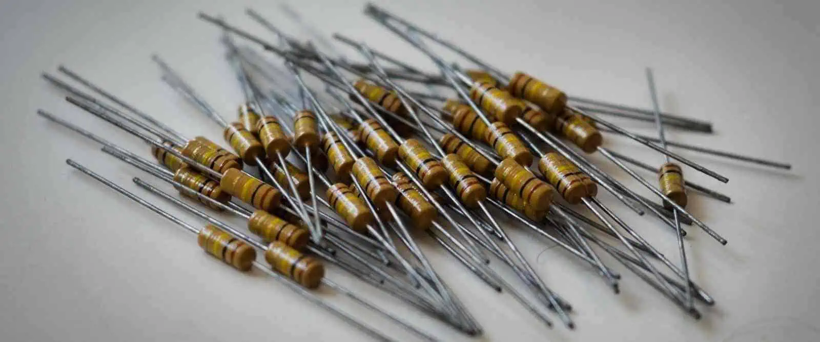
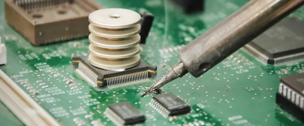
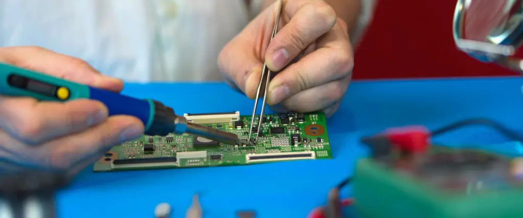
The electrical equipment manufacturing industry is presently going through some robust changes. Electrical equipment are item, appliance, or material used for generating, transforming, or distributing electrical energy. Therefore, electrical equipment manufacturers are involved in the manufacturing of products or materials that generate, transform, distribute, and utilize electrical energy.

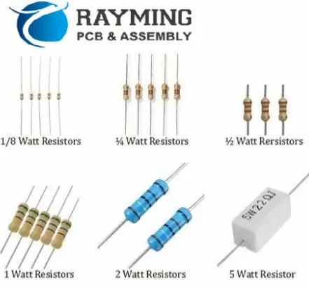
Examples of electrical equipment include electrical meter, non-metallic sheathed cable, single pole switch, circuit breaker, light fixture, and many more. Electrical equipment manufacturers are creating new innovations and ideas to transform the industry. Also, these manufacturers produce conductors, materials, small appliances, amongst many others.

Electrical equipment manufacturers have made a huge impact in the industry by seeking for ways to improve the processes. These manufacturers keep looking for how to innovate and improve communication between their workers and clients. Here, we have the best electrical equipment manufacturers you can work with.

Best Electrical Equipment Manufacturers

Industrial electronics manufacturers

Hitachi Ltd

This multinational company was founded over a century ago by electrical engineer Namihel Odaira. Hitachi Ltd is a Japanese-based electrical equipment manufacturer involved in the production of industrial machinery, heavy equipment, IT systems, defense technology, and more.

This company invested in the expansion of its business in areas like IoT infrastructure, IT, big data, and other solutions that need innovative electrical equipment. Hitachi Ltd was able to achieve this expansion due to its vast experience acquired from previous power generation.

As of now, Hitachi is the second largest producer of electrical equipment in the world. The company has a market capitalization of about 6.47T. Also, it is highly ranked on the Nagoya Stock Exchange and Tokyo Stock Exchange. In the Forbes Global 2000 list, Hitachi Ltd was ranked 129th and 38th in the Fortune Global 500.

This multinational conglomerate has operations in sectors such as nuclear, engineering and electronics, and transportation. Hitachlโ€™s products and services are widely used in applications like healthcare, communications, distribution, industry, manufacturing, and government among others.

Schneider Electric

Schneider Electric is a well-known electrical equipment manufacturer in France. This company offers automation and energy solutions to ensure sustainability and efficiency to serve various industries like data center, marine, utility, pharmaceutical, and electric utility. The companyโ€™s product portfolio includes advanced distribution management systems, variable speed drives, supervisory software for power management, and wireless energy sensor.

This company has more than 100 years experience in the manufacturing of electrical equipment. Schneider Electric has its headquarter in Rueil-Malmaison in France. This electrical equipment manufacturer believes that humans should have access to digital and energy. Therefore, Schneider Electric offers automation digital and energy solutions to various industries.

This multinational company integrates advanced energy technologies, software and services, and real-time automation for Infrastructure, Homes, and Industries. Schneider Electric is dedicated to discovering the infinite possibilities of a global, and innovative community.

Panasonic Corporation

FULL PCB MANUFACTURING Quote

Panasonic Corporation is a Japanese multinational company founded in 1918. This company started with the production of a light bulb socket. With its headquarter in Kadoma, Osaka, Panasonic creates innovation measures and integrative world-class technologies for the production of electrical equipment.

The electrical equipment manufacturer is one of the largest manufacturers of electrical equipment in the world at the end of the 20th century. Panasonic is now presently engaged in the production of consumer electronics. It provides products like industrial systems, rechargeable batteries, home renovation and construction, optical devices, and AC units to lighting.

This electrical equipment manufacturing company is ranked as the 4th largest electrical equipment manufacturer in the world with a market capitalization of 3.26T. Furthermore, Panasonic Corporation is a constituent of TOPIX indices and Nikkei 225. With over 140,000 patents and distribution companies in Asia, Europe, and America, Panasonic employs more than 244,479 workers across the globe.

Panasonic has gained popularity in the electrical equipment industry and is highly preferred among customers due to the quality of their electrical products.

General Electric

As a leader in manufacturing diverse electrical equipment and solution in consumer electronics, General Electric offers a wide range of electrical equipment across several fields like renewable energy, digital, weapons production, and more. It is one of the largest electrical equipment manufacturers in the world.

General Electric is a highly ranked electrical equipment manufacturer in the United Sates. It is ranked as the 33rd largest electrical equipment manufacturer in the U.S by gross revenue. This company has operations in about 170 countries in the world. As a global leader, this company has about 113.28B of market capitalization. Also, this giant electrical equipment company is a large employer of labor as it works it over 174,000 employees across the world.

General Electric was listed among the Fortune 500. The company reveals its plans to invest on new subsidiaries that focus on healthcare, renewable energy, digital, aviation, and more.  The consumer products of this company are visible to the public, but they account for a small percentage of the annual sales of the company.

ELEO

Eleo is a leading electrical equipment manufacturer that specializes in the production of different types of battery systems for various applications. Also, this manufacturer produces various battery systems designed to power one or more appliances based on the demands of the consumer. Eleoโ€™s battery systems are widely integrated in various markets like marine, industrial market, e-mobility, and e-vehicles.

Since Eleo was founded in 2015, it has invested more in creating ideas and innovations to make its battery solutions easily accessible to everyone. The main goal of this electrical equipment manufacturer is to enhance the worldโ€™s evolution to achieve a safer and better world by delivering high-performance battery system solutions to various machines and vehicles. This helps in achieving electrification via installation, plug & play stem, and smart features.

All battery systems produced by Eleo are assembled at their world-class production facility in Netherlands. Their production facility was specially built to ensure reliable and highly robust manufacturing process that guarantees safety standards and high quality of every pack going out of the facility.

Eleo hopes to build a future where customers will be provided with high-performance battery systems that can electrify heir machinery and vehicles.

Samsung Electronics

This South Korean giant electronics corporation is ranked as the worldโ€™s second largest technology company. As a top leader in electrical equipment manufacturing, Samsung Electronics has $22.47 billion as its market capitalization. Presently, this company has sales networks and assembly plants in about 74 countries.

Samsung Electronics works with a great team of professionals who dedicate their time to providing solutions to issues arising in the electrical equipment manufacturing industry. This company specializes in the production of electronic components like semiconductors, camera modules, lithium-ion batteries, image sensors and more for brands like Nokia, Sony, Apple, and HTC.

Samsung Electronics engages in the manufacturing of appliances to telecommunication equipment to computers. According to an estimate, Samsung Electronics will become the leading producer of electrical equipment in the world. With its great expertise and integration of advanced technologies, this company has been able to stay on top of its game.

Its electrical products are widely integrated across several industries like consumer electronics, telecommunications, and information technology among others. Samsung employs cutting-edge technology to achieve its mission and such as become a household name. This company produces about 20% of the total exports of South Korea.

Sentor Electrical

Sentor Electrical is an emerging electrical equipment company founded in 2008. This electrical equipment manufacturer provides security, lightning, cabling, earthing, and other services. Also, this company manufactures a wide range of product which include valves, electrical accessories, and more. This electrical equipment manufacturer is well-known for its expertise in electrical equipment manufacturing.

Sentor Electrical supplies their electrical products to some of the best FM companies and MEP contractors. Also, their products are widely integrated across all sectors like industries, healthcare, power, and government. This company has rights to the In-Country Value certificate of the UAE. Therefore, this enables them to deliver future projects across the UAE region.

As a leading supplier of electrical equipment across the UAE region, this company keeps delivering quality. Sentor Electrical works with a team of highly skilled engineers who are dedicated to creating innovative ideas that will transform the electrical equipment industry and as well contribute to the development of the industry.

If you are looking for a reliable electrical equipment manufacturer, Sentor Electrical is the right option for you.

Mitsubishi Electric Corp

Mitsubishi Electric is popular electrical equipment company in Japan. This multinational company has its headquarter in Tokyo, Japan. As a world leader in the manufacturing of multi-field electrical equipment, this company has over 95 domestic companies in the country. Asides from that, it has 108 international companies across the world.

Mitsubishi Electric is a core company of Mitsubishi Group. In 2020, this company earned over 4,462.5 billion yen as revenue. It has a market capitalization of 3.25T. The production of electrical products like automation parts, air conditioners, semiconductors, high-performance home appliances, trains systems, satellites, and electric motors among others contributed to the revenue generated by Mitsubishi Electric.

The company which was founded in 1921 has more than 70 years experience in the production of electrical equipment. Its product portfolio includes data communication systems, household appliances, heavy electric machinery amongst others. Mitsubishi Electric Corp specializes in the development, production, and distribution of electronic equipment.

This company keeps contributing to the economic growth of Japan. Also, Mitsubishi Electricโ€™s electrical products undergo strict testing and inspection procedures before mass production.  

How to Choose the Best Electrical Equipment Manufacturer

There are several factors to look into before you hire an electrical equipment manufacturing. These factors include:

Level of expertise

You need to consider your manufacturerโ€™s level of expertise especially as regards your own industry. For instance, if you need an electrical product in the consumer electronics industry, you should inquire if your manufacturer specializes in consumer electronics. You need to work with a team that specializes in what you need.

Certifications

You need to be sure your electrical equipment manufacturer has the right certifications. Certifications are ways manufacturers earn the trust of their clients. This assures their clients the quality of their products.

Customer support

Your manufacturer needs to be responsive to your needs. Also, this manufacturer must be able to deliver at your deadline. The best manufacturer will keep you updated as regards your needs and seek for means to meet all your demands.

Challenges in the Electrical Equipment Manufacturing Industry

The manufacturing world is presently experiencing huge changes, even after the pandemic hit. This industry is experiencing challenges like labor shortages, supply chain shortages, and lack of technology. These challenges have been affecting consumers as they are at the forefront of this negative trend. As a result of this manufacturers are seeking for ways to modernize the way they carry out their business.

What challenges are electrical equipment manufacturers presently facing?

Supply chain shortages

Companies are beginning to combine external and internal resources while adhering to international standards. Problems like compliance and traceability are contributing to operational burdens. Also, it is usual for components to go on a long journey before getting to the final consumer.

Labor shortages

Another big challenge electrical equipment manufacturer are faced with is labor shortages. Lack of labor tends to bring a setback to the electrical equipment industry. This industry needs highly skilled and professional engineers, developers, and designers. However, this continues to be a major problem in this industry.

Uncertain demand

Economic volatility can result in fluctuations in production. Consumer preference can lead to spikes in demand for a separate company or product. Furthermore, there should be efficient capabilities to align inventory with demand.

Shrinking operating margins

New innovations are being made in the electrical equipment industry. Global competition is reducing prices of goods. Since most companies need to stay relevant in the industry irrespective of the competition, these companies need to be more cost-efficient.

Conclusion

Electrical equipment manufacturers have made a huge impact in the industry by seeking for ways to improve the processes. These manufacturers keep looking for how to innovate and improve communication between their workers and clients. Choosing the best electrical equipment manufacturer goes a long way in ensuring you get quality products. Several factors like service, experience, and price will influence your decisions.

What is an Inductor Impedance Calculator?

Inductor impedance calculator

Keep in mind that the reactance of the ideal inductor has the same magnitude as its impedance. This phase shift found between the current and voltage in the inductive circuit, nevertheless, prevents them from being exact. Calculations are made using the formula below:

Where:

  • L denotes the inductance, which is measured in henries,
  • XL denotes the reactance of the inductor, measured in ohms,
  • 2ฯ€f= ฯ‰ denotes the angular frequency and measured in rad/s
  • ZL denotes the impedance of the inductor in ohms,
  • f denotes the frequency measured in hertz, and j denotes an imaginary unit.

Enter the frequency and inductance into the calculator, choose the measurement units, and its result would be displayed in ohm.

What Is an Inductor?

FULL PCB MANUFACTURING Quote

The inductor can be described as a passive two-terminal electrical component that primarily consists of a insulated wire twisted into a coil around its magnetic core and, alternatively, an air core. Chokes and coils are other names for inductors. To boost its magnetic field as well as subsequently the coil’s inductance, the magnetic core can be typically formed of ferromagnetic metal, such as ferromagnetic ceramic or iron.

Just like the capacitors, the inductors are useful in storing energy. Inductors, as opposed to capacitors, store their energy in magnetic fields that surrounds them. Inductors are employed in filters, which can be used to reduce ripple in the output of direct current or stop the transmission of radio frequency interference through cables.

In the tuned circuits present in radio receivers and transmitters as well as in transformers, inductors are frequently utilized.

Inductors vs capacitors

Inductors oppose rate of current change flowing via them as opposed to capacitors that support rate of voltage change across the plates. The inductors are able to easily transfer the DC current via them, in contrast to capacitors, which cannot.

The ability of inductors to resist the current is proportional to an inherent property known as inductance. This is denoted by L, which honors Emil Lenz, a Russian physicist and it is measured in H (henries), which is also named after Joseph Henry, the American scientist. Inductors can only resist changing current or AC.

Inductors vs Resistors

The inductors oppose variations in any current passing through them, as opposed to resistors, which merely oppose the current that passes through by producing a voltage that is precisely proportional to current. In direct proportion to the pace at which the current passing through changes, they produce a drop in voltage. Its induced voltage’s polarity has always been such that it’s attempting to keep a changing current in its current condition.

For instance, the voltage has a tendency to fight a rise in current and maintain a lower current whenever there is an increasing current, and the opposite is true when this current is dropping. A higher back voltage is always produced by current changes that occur more quickly.

This voltage can be referred to as “back emf” due to its characteristic. Reactance is a term used to separate this characteristic of coils against resistance. When a coil gets sinusoidal voltage, higher frequencies result in faster change rates, making the coil more resistive to current and increasing its reactance, according to the graph.

Given an inductance, the graphical representation of the reactance XL of an ideal inductor and the flowing of current through it against frequency reveals that the reactance is directly proportional to frequency and the current is inversely proportionate.

Measuring the Impedance

The first involves the resistance, denoted by R, which slows down the current due to the form and material’s poor electrical conductivity. The opposing magnetic and electric fields cause the reactance, which was previously explained, to delay the current.

The impedance, denoted as Z has two components: one is the real and imaginary parts, with its measurement done in ohms.

The only thing limiting the continuous DC current that flows through the real inductor when it is linked to the DC source is the inductor’s low resistance wire. The power source’s internal resistance as well as the inductor’s internal resistance dictate the amount of current that will flow via the coil as well as when the inductor is attached to the constant DC voltage source.

The inductor coil’s self-induced electromotive force prevents the current from rising quickly and “fights” the voltage level until current reaches its maximum level.

The current that flows via the inductor will gradually decrease to zero if the source of DC current is unplugged, and the inductor’s back emf will once more “battle” against the change in current and work to maintain the current. The current will eventually gradually decrease to zero.

What happens in Purely Inductive Circuits?

Current and voltage are 90ยฐ apart in a circuit that only uses inductive components.

  • the current stands at a negative maximum; the change rate is zero, while the voltage is also zero;
  • the current stands at zero, its change rate is maximum, while the voltage stands at the positive maximum;
  • the current stands at the positive maximum, its change rate is zero, while the voltage stands at zero
  • the current stands at zero, its change rate is maximum, while the voltage stands at the negative maximum;

The current would lag behind voltage by a certain phase angle if the alternating sin voltage is placed along a coil.  Its phase angle would be 90 degrees or one-fourth of a specific cycle for the pure inductor. positive maximum voltages are present across the inductors at the time axis position, when the current stands at zero. A magnetic field gradually develops around the coil as well as the current as time goes on. The emf is generated by the magnetic field and opposes the current.

What is Electromotive Force (EMF)?

Since this current stands at zero at this location and the variation in the current has reached its highest, this emf, representing the reaction to the fluctuation of the current passing through it, is at the maximum. The sine current change’s rate is zero whenever the current reaches its maximum (negative or positive), and back emf also stands at zero during these times. The wave of voltage is thus 90ยฐ out of the phase with current wave. This means that either the voltage comes first or current comes last.

Think of the following analogy: Sunlight is at its strongest at astronomical noon, but the hottest time that day is typically several hours later.

The months that are coldest have not yet come; depending on where you reside, they could be January or February. Alternatively, winter solstice inside the North Hemisphere (shortest day) occurs at the December ending. This “phase shift” or “seasonal lag” is brought on by the massive oceans of the Earth’s absorbing the Sun’s radiation. They then gradually release it, just like inductances do.

What Is Calculated Impedance?

The resistance of an inductor to a signal traveling through it at a certain frequency is measured by the impedance that has been calculated. The AC voltage’s changing frequency applied causes a change in inductive reactance. The XL reactance of the inductor is great at higher frequency and tiny at low frequencies, as shown by the graph and formula (capacitors act in an opposite way).

Its inductive reactance increases significantly or completely opposes the current at high frequencies. High-frequency currents are stopped by an inductor. On the contrary, an inductor transmits very effectively at really low DC voltage or frequencies, which is why the rule we learnt in high school is that inductors block the AC and then pass the DC. Inductors pass the signals extremely well whenever there is very low frequency. Inductors are used in crossovers to keep high frequencies away from reaching the subwoofer drivers.

Like resistance, the impedance can be expressed in ohms. Similar to resistance, impedance displays how resistant an inductor is to the electric current flow. How does impedance vary from simple resistance, though? The distinction is that the impedance now depends on the frequency of the signal. Whereas inductors’ impedance is depending on frequency, resistance is frequency-independent. At rising frequency, inductors’ impedance lowers.

The optimal inductors are the focus of this calculator. Real inductors have resistance connected in series pattern with its inductance at all times. To get the impedance of actual inductors, use the inductor impedance calculator.

Conclusion

We hope you now know how to use the inductor impedance calculator. To use the inductor impedance calculator, just enter the frequency and inductance into the calculator, choose the measurement units, and its result would be displayed in ohm. The inductor can be described as a passive two-terminal electrical component that primarily consists of a insulated wire twisted into a coil around its magnetic core and, alternatively, an air core. Also, The impedance, denoted as Z has two components: one is the real and imaginary parts, with its measurement done in ohms. In addition, the resistance of an inductor to a signal traveling through it at a certain frequency is measured by the impedance that has been calculated.

What Does PCB Screen printing Entail?

PCB Screen printing

PCB screen printing for long has been a very important part of PCB manufacturing. It is utilized in a variety of procedures, including plating and putting resists to its copper surface as well as adding peelable and solder resists.

It’s definitely accurate to state that the use of screen printing has decreased as technology developed over time. This is most likely because the PCB screen printing capabilities are limited by PCB design’s technological requirements. As an illustration, it will be very challenging to apply the solder resist picture with a similar level of precision and definition to the modern Circuit board with several surface-mounted pads.

What Does PCB Screen Printing Mean?

A tool, such as a stencil or mesh, is used in the printing technique known as PCB screen printing for transferring solder paste and ink onto the circuit board surface or in the PCB microvias and vias. A reversing stroke allows the screen briefly touch its substrate across a contact line after a squeeze or blade is used to move throughout the screen and fill the apertures of this tool with ink.

Even as screen bounces back after its blade has crossed, the ink wets the substrates, then it is drawn away from the tools apertures due to this. PCB assembly and PCB manufacturing both use PCB screen printing.

What does a PCB’s Silkscreen Offer?

PCB Screen print

The last step in the circuit board manufacturing operation is to add a silkscreen layer. A layer known as silkscreen employs ink traces for identifying all of the Circuit board components, the test points, PCB parts, warning symbols, marks, as well as logos, among other things. These letters, numbers, and shapes aren’t really a new language. Moreover, they can convey the purpose of each pin. Although it’s possible that silkscreen is sometimes used on a solder side, which raises the cost, this silkscreen gets applied onto its component side. In order to discover and identify the components, a thorough PCB silkscreen would be helpful to both the engineer and manufacturer.

Epoxy ink that is non-conductive is what is used. These markings are made with carefully formulated ink. Although silkscreens could be of any color, the three common colors which are typically utilized are white, black, and yellow. You will undoubtedly come across Boards with red, gray, and blue silkscreens if you disassemble enough devices.

Why would someone use the silkscreen layer?

In PCB boards, the silkscreen isn’t really typically used. Customers must request this, and adding a silkscreen onto the circuit board typically entails an extra fee. The following are some significant advantages of selecting a silkscreen layer:

  • This aids in locating test spots on the Circuit board for the benefit of engineers and personnel. They can take measurements after this point and it helps with troubleshooting.
  • Also, it may be utilized to indicate the locations on the circuit board where components should go so that users don’t forget to do so.
  • These warning symbols that are typically used to signify the greater parameter values, including voltage, power, and current, benefit from silkscreen coating as well.
  • It serves as the reference indicator for identifying the type of component as well as polarity orientation, which could be used to indicate values of resistors, inductors, as well as other components, decreasing the likelihood of inserting a component using the incorrect value present on the circuit board.

What Information Is Provided by a Silkscreen?

FULL PCB MANUFACTURING Quote

A silkscreen might not be necessary for a Circuit board to function, but it is nevertheless valuable for the info it conveys.

For example, it will assist anyone in:

  • Recognizing any warning symbols
  • Parts’ polarity;
  • Test-point identification
  • Identify the components using reference designators.
  • Recognize the circuit board-specific numbers.
  • Recognize manufacturer markings, version numbers, etc.

Silkscreen Printing Techniques

Three methods are used to apply the silkscreen to the PCB:

Manual PCB Screen Printing

Whenever line widths were larger than 0.007 or the registering tolerance is at 0.005, this is performed for PCBs. Utilizing a stencil with traces and text, manual pcb screen printing can be done. Nylon is used to create the traces. And through stencil, the ink gets applied to the laminate or layer. The ink then is dried in a baking oven after that.

Among the simplest methods for making the silkscreen layer, it also allows huge font size. Years may be needed to master this art.

LPI – Liquid Photo Imaging

When its screen printing lines is thicker than 4 mil, the technique is utilized. The LPI procedure is quite similar to the application of the solder mask procedure. The laminate is covered with epoxy in this procedure, though, and then exposed to UV light after that. After that, the board gets created and cured. Compared to manual PCB screen printing, this method guarantees more precision.

Compared to the two PCB screen printing types, LPI employs white color and uses more ink. For this kind of printing, the time required is lengthy.

DLP: Direct Legend Printing

Among the remaining three procedures, DLP is among the costliest. Acrylic inks as well as the inkjet projector are both employed in this procedure. Using CAD software, the ink gets applied onto the PCB. The Ultraviolet light is then shone on the ink. This acrylic link would be inappropriate for Boards that might be finished in silver.

Conclusion

On a Circuit board, you ought to desire a PCB screen printing. It makes it simple for users to comprehend your Circuit board as well as how it was put together because it informs you where each component is located. Add a silkscreen when ordering PCBs. Your Circuit board will receive a silkscreen from the manufacturer. The quality of this would be much better than any DIY PCB screen printing.

If you desire a printed circuit board that best meets your needs and tastes, communicate openly and frequently with a contract manufacturer. Inform them you desire a silkscreen right away and go over the details.

What Does Soldering Flux Mean?

soldering flux

Chemicals called soldering flux are used both before and after soldering electrical components. Both automated and manual soldering procedures can be carried out using soldering flux. In order to clean and remove any impurities or oxides from these metal surfaces prior to soldering, soldering flux can be mostly used.

Whenever metals get exposed to air, chemical compounds known as oxides are created. A flawless solder joint cannot form within existence of oxides. Metal oxides may cause electrical conductivity as well as inefficient electricity flow across electrical boards or circuit boards, which may be present on circuit boards. Solder flux is also used for the following reasons:

  • Prevent the metal’s surface from reoxidizing while soldering.
  • Assist in lowering the viscosity and surface tension of such molten solder. It enhances the wettability.
  • This flux enables this molten solder that permanently unites two mechanical and electrical components.

How do I choose the right soldering flux?

No Clean Flux

Halides are the foundation of fluxes’ method of activity. Higher halide content present in the flux will improve performance by eliminating any generated metal oxide upon that metal surface thus strengthening the joint. High activity fluxes frequently leave corrosive residues on that soldering surface. It might lead to issues with the product’s dependability.

Two things need to be taken into account when performing electronic assembly.

Before as well as after the soldering, the flux must be inactive. Secondly, this should stay operational for the whole soldering procedure. This aids in preventing the oxides and tarnish that can build because of high temperatures used when soldering.

To keep the surface for soldering ready for the soldering, proper soldering iron fluxes should operate just beneath the temperature for soldering temperature. Extremely active flux also isn’t advised because to the undesirable by-products which cause reliability problems.

The fundamental drawback of these fluxes is they are ineffective even during high temperatures. There are currently neither clean fluxes available to address this issue. Activity and cleanability should be balanced in a good solder flux. The majority of non-clean fluxes lack halides. The primary component of them is organic acid.

How is soldering flux used?

Solder flux is available as a liquid or paste. While the changes in the liquid are held in flux pens or bottles, the majority of solid flux are kept in tiny jars or tins. Use all safety preventive equipment when soldering to improve your security. A breakdown on how to utilize a soldering flux is provided below.

Use the right solvent to clean your metal surface. This aids in cleaning out dirt, grime, and certain metal oxides that may have built up upon that soldering surface. Apply a thin, even layer of flux onto the surface for soldering.  At this point, you just aren’t permitted to warm the surface.

Place a soldering gun on these metal plates coated with the flux when it is sufficiently hot. All metal oxides must be eliminated by melting the flux with a soldering gun and spreading it over the entire metal surface. Once this flux has dissipated, add a soldering wire. By doing this, its solder will bond prior to reoxidation.

Solder Flux Types

FULL PCB MANUFACTURING Quote

Inside the electronics sector, soldering flux comes in three main varieties. An outline of each is provided below.

Rosin Flux

The oldest form of flux is rosin flux. Natural resins from pine trees are used to make the flux. To improve performance, present day rosin flux gets combined with other fluxes. This kind of flux generally flows easily, particularly in warm temperatures. Both foreign materials and metal oxides are eliminated by the flux.

Although resin flux appears naturally acidic, once it has solidified, it turns inert and can be kept on soldering surfaces without having to endanger the circuit. It is advised to remove the flux when soldering is done because this circuit could warm up as well as liquefy any flux.

Organic acid Flux

Water-soluble flux is another name for this soldering flux. These organic acids, including stearic, lactic, and citric acid, are used to make this sort of flux. After that, organic solvents like isopropyl or alcohol are added to the acids.

Metal oxides can be removed more successfully using organic acid fluxes. Additionally, it is simple to clean and has strong soldering activity. Never leave organic acid flux on any soldering surfaces, particularly circuit boards. Soft soldering is the major application for this soldering flux.

Inorganic Acid Flux

Brass, copper, and stainless steel are stronger metals that perform well with this soldering flux. You must carefully clean your soldering surface then get rid of any corrosive remnants before employing inorganic flux. Last but not least, non-electrical soldering can be done using inorganic acid flux.

Applications of Soldering Flux

Soldering Circuit Boards

Flux might be in the form of a solid, liquid, or paste form. Depending on the soldering method being used, it could be applied to a Circuit board in a variety of ways:

Hand soldering: This involves manually applying flux. You can use handmade applicators or solder pens. Some soldering wire types are made with flux and solder together. If so, melting the wire onto the surface having the soldering iron would cause the flux to dissolve.

Wave soldering: Prior to the board traveling via solder wave, flux gets sprayed on it.

Reflow Soldering: When reflow soldering, the flux gets applied as paste made of gooey flux as well as small metal solder spheres.

How do I use Soldering Flux?

Soldering flux can be purchased in the form of paste in tiny jars or tin cans, liquid in bottles or jars, as well as flux pens. Organic flux, which is primarily used during soft soldering, while inorganic flux that is acid-based may be employed in different non-electrical applications. As a result, flux utilized for brazing and soldering is typically inorganic; however, this may comprise organic chemicals that become active at extremely high temperatures.

Utilize solder flux as described below:

Before applying your soldering flux, users should clean any metal contact using a reliable solvent to get rid of any possible dirt, grime, and excessive oxidation.

The surfaces in which this actual soldering will take place must next be covered evenly with the flux. You should be aware that it cannot heat during this point.

As soon as the soldering gun’s tip is ready and hot, this should be put on metal contacts that have been covered in flux. Until this flux is present, this should melt that flux, spread across the surface of the metal, and eliminate its oxide layer.

After the vaporization of the flux, this should introduce as well as melt its soldering wire, ensuring this solder bonds even before oxidizing goes on again to ensure that the soldering is effective.

Soldering Flux Alternatives

PCB soldering problems

Any substitutes for soldering flux? Although you may solder without flux, you still require something to remove the metal surface’s oxides. Unless you do this, you risk damaging the surface as well as leaving it poorly cleaned while soldering. Petroleum jelly can be described as a natural anti-corrosive option to the soldering flux that won’t harm your circuit board or material.

Soldering flux should be used to guarantee a solid bond that won’t short out or corrode. No matter how thoroughly you clean that metal surface, a flux is still required in order for the solder to attach. Soldering flux is advised since without it, the solder junction just won’t be sturdy or conducting enough.

Moreover, solder will follow a source of heat, and without the soldering flux, it could be challenging to remove any molten solder from your iron.

Why Do We Use Solder Flux When We Solder?

Flux’s primary application in any circuit board rework or assembly is to clean as well as remove all oxides and contaminants from the PCB. Due to the oxides that have been deposited onto the board, it might have poor solder joints, which would result in an electrical conduction that is poor coupled with poor flow via the circuit.

The effects of soldering flux are favorable for both wetting, soldering, and deoxidizing metals (the copper tracks present on the circuit board as well as leads of the electronic components). By eliminating oxides as well as other surface impurities, the activators inside the flux encourage wetting of such molten solder onto the lands of the surface mount as well as component leads or terminations.

Cleaning the Soldering Flux

During the soldering procedure, it’s crucial to clean your board to get rid of any undesirable flux residue which might degrade the board’s functionality or even result in short circuits. There is no cleaning required for no-clean flux. Aqueous cleaners or solvent cleaning can be applied to fluxes that require cleaning following soldering. Most manufacturers of soldering flux also offer flux cleaners.

Conclusion

There can be no doubt that soldering flux plays a key role during electrical soldering. Metal oxides on soldering surfaces can be cleaned and removed with the use of soldering flux. In addition, soldering flux plays a huge role in the prevention of oxidation from the surfaces of the metal during soldering.