
RAYPCB · ENGINEERING GUIDE
High Voltage Ceramic Capacitors: Ratings, Stored Energy and PCB Integration
High voltage ceramic capacitors must be selected for their actual electrical function and operating conditions. A printed voltage rating does not by itself establish suitability for repetitive pulses, a safety-isolation role or every mounting environment. The PCB design must preserve the required spacing and mechanical support around the chosen component.
This page supports component-integration review. The energy calculator uses an ideal constant capacitance to show stored energy and charge. It does not design a discharge circuit, approve a voltage rating or determine safe handling procedures.
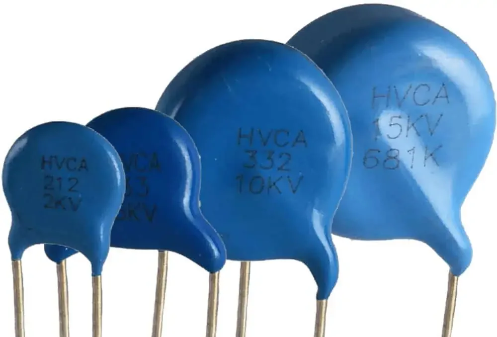
Define the application before the package
Identify whether the capacitor provides filtering, coupling, pulse storage, suppression or another function. Record DC bias, AC content, repetitive peaks, temperature and expected stress. A part suitable for one role may not be suitable for another at the same nominal voltage.
Use the exact manufacturer part number and current datasheet. Keep electrical ratings, test conditions and approved applications together. Package appearance or a distributor category cannot establish the component's complete operating limits.
Understand effective capacitance
Ceramic capacitance can depend on dielectric type, voltage, temperature, frequency and time. A nominal capacitance value may not be the effective value at the intended operating point. Obtain the manufacturer's relevant curves or model for the exact part.
For nonlinear capacitance, stored energy requires the appropriate voltage-dependent relationship rather than simply substituting a nominal value into one equation. The calculator here assumes a constant linear capacitance and labels that boundary explicitly.
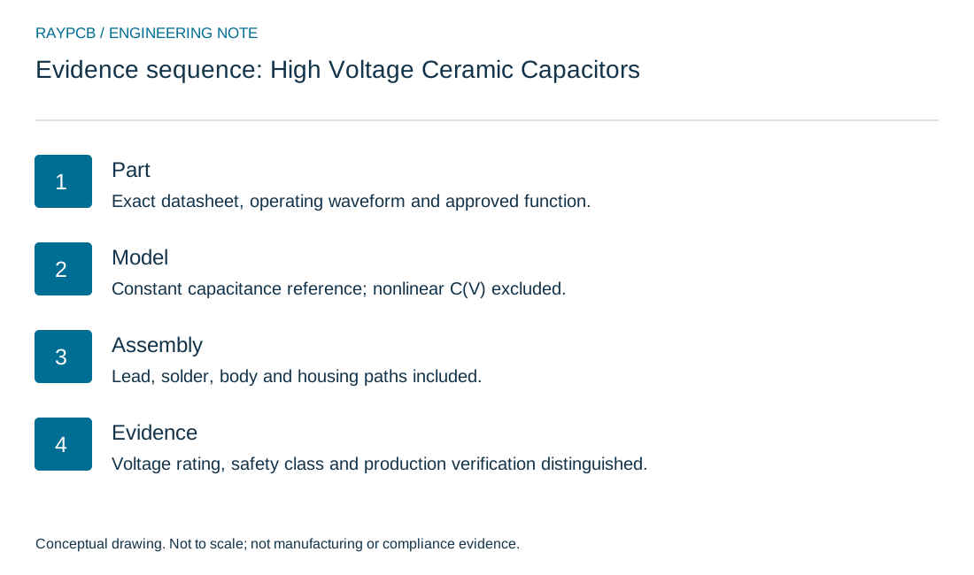
| Review item | What to establish |
|---|---|
| Part | Exact datasheet, operating waveform and approved function. |
| Model | Constant capacitance reference; nonlinear C(V) excluded. |
| Assembly | Lead, solder, body and housing paths included. |
| Evidence | Voltage rating, safety class and production verification distinguished. |
Check the simple energy reference
For a linear capacitor, energy is one half of capacitance times voltage squared, and charge is capacitance times voltage. An illustrative 0.01 µF at 1000 V stores 0.005 J and 10 µC in that ideal model.
The calculation does not establish whether a component or assembled circuit is safe to touch, test or service. Stored energy, connected sources and the complete equipment design need the applicable safety controls. This page deliberately does not provide an energized test or discharge procedure.
Separate voltage rating from safety class
A high voltage rating and approval for a particular safety-capacitor function are different matters. If the component bridges an insulation barrier or connects to a mains-related circuit, select the required approved class and conditions through the applicable equipment design review.
Murata's overview of certified capacitors in power-line noise suppression provides category context. Use actual certification and datasheet evidence for the selected part; do not infer a safety class from the voltage number alone.
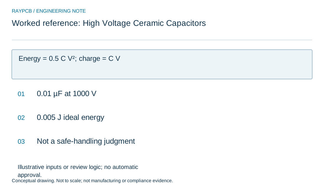
Linear capacitor energy reference
Linear capacitor energy reference
Use the current inputs and keep the assumptions
Start with the physical boundary named above the inputs. Enter your own values, or select Load example to explore the labeled teaching case. Example mode stays visible after edits so an illustrative calculation is not mistaken for measured project data. Clear for my inputs removes the sample values and starts a separate record.
Generate the result after completing every field. Changing any input invalidates the previous output and disables its download until you calculate again. Read the limitations below the numbers: a geometric or arithmetic result does not qualify a material, approve a circuit or establish manufacturing capability.
Download the current result if it helps the review. The text file contains inputs, outputs, assumptions and the tool version. It stays on your device; attach it manually to an enquiry if useful. No CAD is uploaded or interpreted, and nothing is automatically inserted into the Contact form. You can request an engineering review without completing this tool.
| Input | What to establish before using it |
|---|---|
| Review reference | Use a nonconfidential scope or revision. |
| Effective constant capacitance · µF | Ideal linear value. Nonlinear ceramic C(V) needs integration. |
| DC voltage · V | Magnitude only; no voltage rating or isolation certification inferred. |
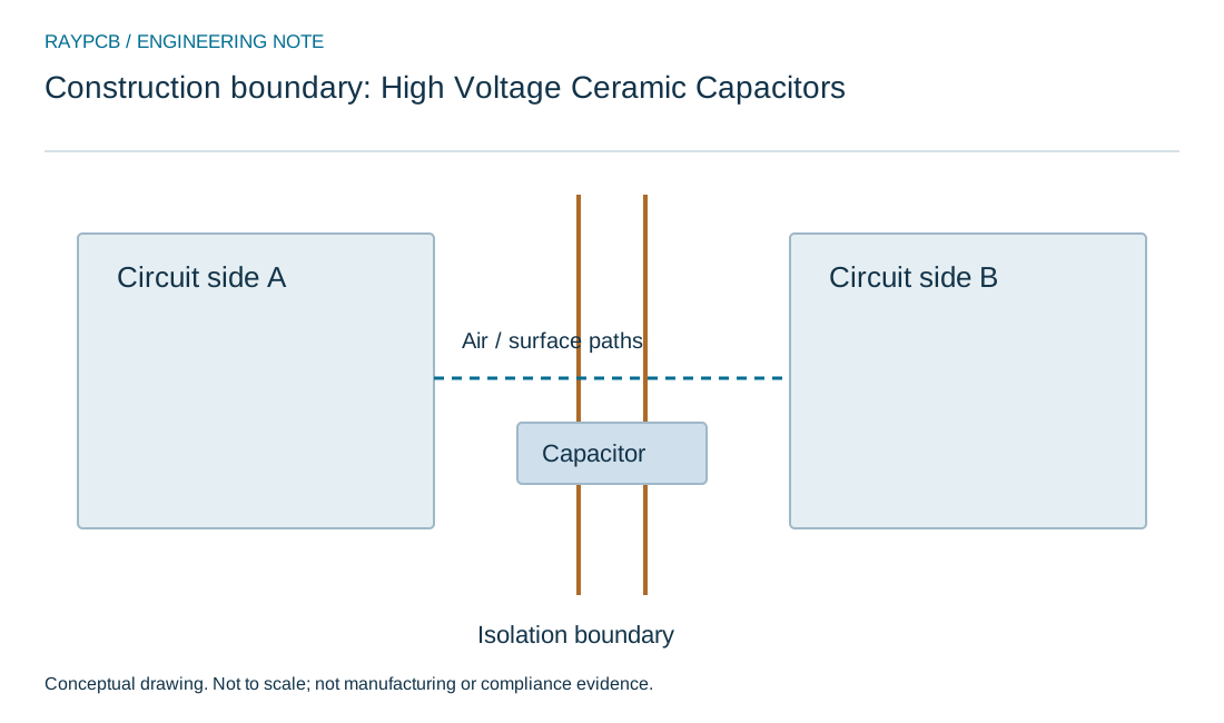
Preserve spacing around the assembled part
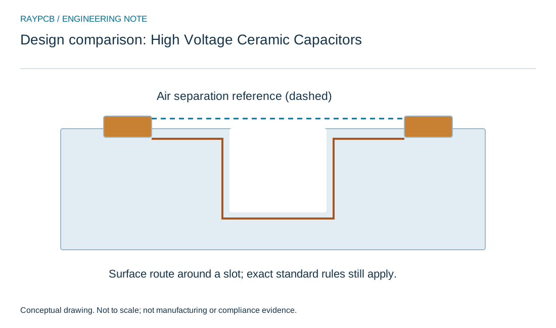
Review lead forming, solder fillets, component body position and neighboring conductors. The shortest air and surface paths in the assembly can differ from the pad-to-pad distance in CAD. Include tolerances and the installed relationship to metal housings or fasteners.
Use high-voltage PCB design for the barrier brief. A capacitor body does not automatically make an adjacent PCB path irrelevant. Keep the complete physical insulation system in view.
Review mechanical and assembly stress
Follow the component manufacturer's soldering, lead-forming and mounting guidance. Mechanical stress, board flexure and thermal exposure can affect ceramic components. A larger package or heavy leaded component may require a different support arrangement from a small surface-mount part.
Keep assembly instructions and inspection criteria attached to the part and board revision. Do not substitute a similarly rated component without checking footprint, lead spacing, body envelope and the relevant electrical behavior.
Verify the operating point and evidence
Check the selected component against the circuit's actual voltage waveform, temperature and frequency. Define qualification and production verification through the responsible engineering process. A generic capacitance check does not validate every stress in the application.
Retain part identity, source and applicable evidence in the BOM review. If an alternative is proposed, record what was compared and what remains unverified. Treat incomplete curves or approval information as a decision gap rather than assuming equivalence.
Prepare the PCBA enquiry
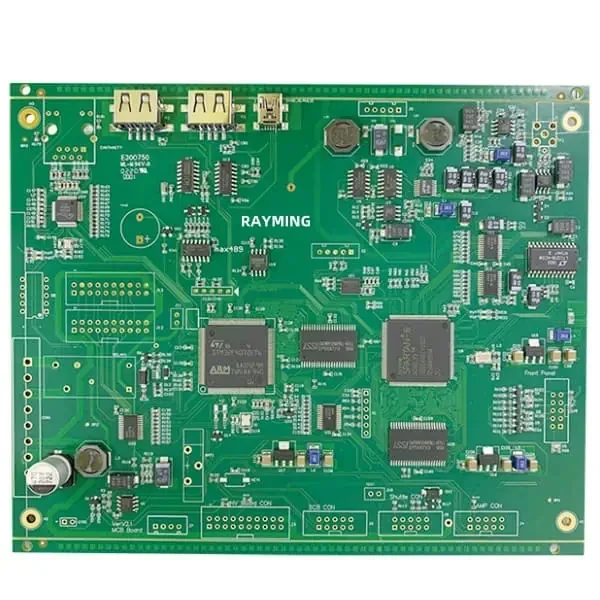
Provide the exact BOM, schematic, layout, component drawings, insulation requirements and assembly constraints. State any prohibited substitutions and the verification scope you need. Use the PCB assembly service for the populated-board route.
The tool's local record can communicate an ideal energy calculation, but it is not an approval document. RAYPCB's fabrication and assembly review should be based on the actual files and agreed requirements, with end-product electrical safety evaluated separately.
Keep the insulation evidence connected to the product
Create a barrier schedule that identifies the circuits and accessible parts on each side, the required insulation function and the document that establishes it. Link this schedule to schematic nets and physical locations. A spacing table without that mapping can be applied correctly to the wrong boundary.
Review the assembled extremes, including component bodies, lead forming, solder, hardware and surface condition. The relevant path may change between a bare board and the finished product. Where coating, potting or a special material is part of the assumption, include its qualified process and verification evidence.
Treat design qualification and routine production checks as separate activities with explicit acceptance criteria. A successful test result proves only what that test and configuration support. Keep responsibility for equipment-level safety decisions with the project's qualified engineering and conformity-assessment process.
Before release, place the chosen requirement, the proposed construction and the evidence in one review record. Separate measured values from supplier nominal data and from your own assumptions. If a value is unknown, identify who will obtain it and what decision depends on it. An empty field is more honest and more useful than an invented typical figure.
During an A/B comparison, change one relevant variable where possible. Preserve the original inputs and the reason for the change. If several things change together, describe the result as a comparison between complete configurations. Do not attribute the entire difference to one material or geometry feature without supporting evidence.
For a repeat order, confirm that the relevant drawing, material and process revisions still match the accepted configuration. Record alternatives explicitly. This small discipline helps purchasing avoid an apparently equivalent substitution that changes the engineering basis of the original decision.
Standards, source context and limits
Use the actual applicable document and edition for contractual requirements. Public technical resources help explain methods, but do not reproduce every condition in a licensed standard or qualify a particular RAYPCB construction. Retain exact grades and test boundaries when reading supplier data.
The numeric examples on this page are illustrative inputs unless specifically identified otherwise. Archive photographs show relevant physical context; they are not current equipment, material-grade or inspection evidence. Original drawings explain the models and are not production drawings. Ask for the evidence and acceptance scope needed for your project rather than inferring approval from an image or calculator result.
For fabrication scope and the agreed construction requirements, see PCB manufacturing.