Top Aviation Engineering Services Companies in the World and What they Offer

Aviation Engineering Services

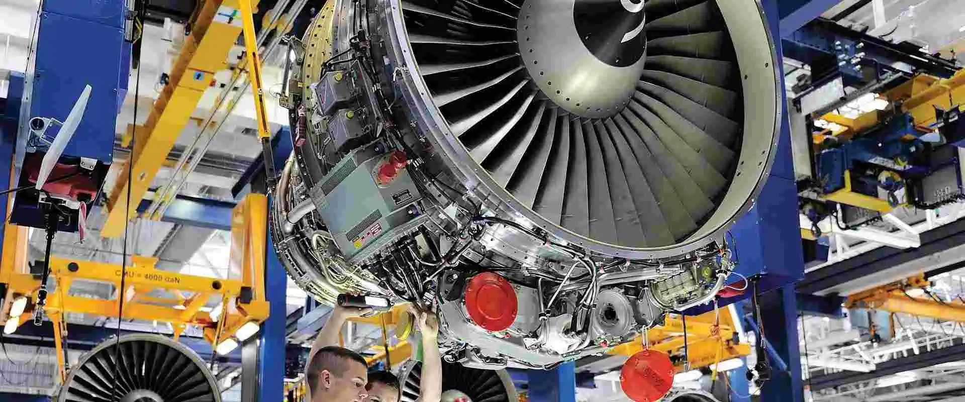
There are different branches of engineering. These include mechanical engineering, civic engineering, chemical engineering, and aviation engineering among others.  Aviation engineering deals with the design, development and navigation technologies of aircraft. Also, it involves airspace development, aerodrome planning, and airport design. Our main focus in this article is the aviation engineering services. We will discuss what aviation engineering entails and what aviation engineering services offer.

What is Aviation Engineering?

Aviation engineering deals with the design, development and navigation technologies of aircraft. Also, it involves airspace development, aerodrome planning, and airport design. This branch of engineering also deals with the formulation and integration of public policy, regulations, and laws as regard aerodromes, airspace, airports, and airlines.

It is important to know that aviation engineering is entirely different from aerospace engineering. Aerospace engineering deals with the event of aircraft and spacecraft. Also, aerospace Engineers are involved in the designing and testing of spacecraft, missiles, and aircraft. These engineers develop propulsion systems and assess the performance of aircrafts. Furthermore, they ensure all products, blueprints, and prototypes meet the requirements of engineering and environmental standards.

The requirements of aviation span across several departments such as IT providers, fuel suppliers, and ground handling services among others. However, there are several service providers that help in meeting these requirements. Nevertheless, it is quite challenging to get an aviation engineering service that understands the business requirements and as well identifies the pain points and effectively implement the proper strategies.

What are the Duties of an Aviation Engineer?

You might have been wondering what the duties of an aviation engineer entails. Well, aviation engineers carry out a lot of tasks. These engineers have a lot of duties to perform. Below are some job duties of an aviation engineer:

  • Maintenance of the quality of different aircraft
  • Designing, developing, and testing of aircraft
  • Management of internal control systems that are within aviation design
  • Simulating flying situations
  • Implementing comfort and safety procedures for possible passengers
  • Troubleshooting aircraft systems and equipment-related issues
  • Partnering with industrial manufacturing designers and electrical specialists
  • Meeting certain timelines for every project

What Skills Should a Successful Aviation Engineer Have?

An aviation engineer should have some special skills. Most times, these skills arenโ€™t taught, they are developed over time. Also, they are often innate. These skills are beneficial for these engineers as they help them carry out their responsibilities easily.

An aviation engineer must have technical and analytic skills to create working designs. Furthermore, an aviation engineer must be able to work with a team since multiple engineers are required to work on the same project. Also, this engineer should be able to coordinate the efforts of their team members and as well meet deadlines. Aircraft design process can be a very long one. Therefore, an aviation engineer needs problem-solving skills, persistence, and creativity. Below are some skills an aviation engineer should have

  • Creativity
  • Strong interpersonal and communication skills
  • Highly collaborative
  • Math and physics skills
  • Strong analytical and technical skills
  • Persistence
  • Excellent problem-solving skills
  • Patience

What is the Difference Between Aviation Engineering and Aeronautical Engineering?

FULL PCB MANUFACTURING Quote

Sometimes, people think aviation engineering and aeronautical engineering are the same. Once they hear aviation, they think it has everything to do with aircraft and aerospace. It is important to understand that these two branches of engineering are completely different from each other. An aviation engineer carries out different tasks from an aeronautic engineer.

Aviation engineering deals with the development of airspace, aircraft navigation systems, the designing of designs, and the planning of aerodrome. This branch of engineering is very crucial to innovation process. Aviation engineers usually control and regulate the design process for military aircraft.

Aeronautical engineering involves the design, development, and testing of flight-capable machines such as drone, aeroplane, missiles, and helicopter. Also, aeronautical engineering is one of the branches of aerospace engineering.

While aeronautical engineers work on systems that function within the atmosphere of the Earth atmosphere, aviation engineers work on mechanical elements, flight systems, wing or body materials,  airspace navigation systems, and other aspects of aviation.

Furthermore, aeronautical engineers work in several locations. They work in places where they can check aerospace assets. Also, you will find them in office environments where they design plans for future developments. Aviation engineering helps in minimizing air emissions, reducing costs for extensive operation, and minimizing aircraft noise.

What do Aviation Engineering Services Offer?

Since we all understand what aviation engineering entails we can now discuss what aviation engineering services offer. Aviation engineering services provide insights into the supply of aircraft accessories and as well cater to the needs of airline companies. Also, these service providers offer consultation to create a strategy that optimizes opportunities for airlines.

The aviation engineering industry is a high-profile one. This industry enhances a portion of world trace, economic growth, and global investments which make it the brain behind globalization. Since it is a capital-intensive industry, it is crucial to have insights into the market. Therefore, this makes it crucial to choose the right aviation engineering services. There are a wide range of aviation engineering services.

Top Aviation Engineering Services

Probe card pcb

In this section, we will discuss a handful of the best aviation engineering services. This will help airline companies to work with the right partner. Also, we will be evaluating the technical prowess of these companies and as well consider the ability of the vendor in providing services. Also, we will pay attention to the Skills, expertise, and competence of these service providers.

Flight research

Flight Research was founded in 1981 and has continued to provide aviation engineering services since its inception. This aviation engineering service provider deals in aviation training and flight test. Also, it focuses in three distinct but interrelated areas which are Defense Contractor Services, Advanced Flight Training, and Flight Test. Furthermore, Flight Research offers training in spaceflight and all types of aircraft.

Flight Research operates a fleet of over 35 aircraft that ranges from twin turbo aircraft to helicopters and supersonic fighters to piston engine aircraft. Another interesting thing about these companies is that they provide aftermarket support to clients.

Xtreme Aviation

This aviation engineering company offers engine services, testing platforms, and full maintenance MRO. Furthermore, Xtreme Aviation offers a wide range of services like engine and landing gear swings and interior reconfiguration as regards to heavy maintenance provision. This company offers a wide range of examinations to ensure functionality and safety. Furthermore, this company carries out final checks of each serviced engine. Its testing platforms are at the Miami-Opa Locka executive airport.

Xtreme Aviation offers exceptional aviation engineering services to clients. This company works with a team of experienced and skillful aviation engineers. Their engineers have the qualification required in the aviation engineering sector.

GA Telesis

GA Telesis emerged as the biggest commercial aerospace company in the world. This company offers a wide range of high-quality engines, aircraft, and components. Also, it offers services such as maintenance and solution-based services. GA Telesis has several integrated business units that help in optimizing the value of commercial engines and aircraft.

One of the benefits of choosing this aviation engineering services is that they have a positioned distribution and maintenance facility. This facility is managed by a team of professional aviation engineers with extensive experience in the industry. GA Telesis has co-invested in assets and companies related to aerospace. With its headquarters in Fort Lauderdale, Florida, this company has continued to offer the best.

Allen Aircraft Radio

Allen Aircraft Radio provides a wide range of products and services to the aviation industry as a whole. Also, it is one of the aviation engineering services companies that offers aftermarket support. AAR trades while planes, airframes, and overhaul engines. Also, it produces certain components. With its maintenance facilities in Oklahoma, New York, Miami, and London among other, AAR offers world-class aviation solutions.

It provides aviation services for commercial and government customers in more than 100 countries across the world. Allen Aircraft Radio has more than 50 years industry expertise and experience. The team of this company focuses on delivering innovative technical solutions to improve competitiveness among their customers.

Precision Aircraft Solutions

This aviation engineering services company is a world leader in the aviation industry. With its headquarters in Beaverton OR, this company is a world leader in aircraft modification. Also, Precision Aircraft Solutions converted the Boeing 757-200 aircraft to freighter and combi configurations. Its clients include ATI, DHL, and SF Airlines among others.

This aviation engineering services provider supplies more resources to increase raise returns and leverage assets. This company doesnโ€™t only purchase aircraft, it designs, repairs, changes, and integrates parts of aircraft. Precision Aircraft Solutions can design structures, kit to conversions, and more. This company offers some of the best and reliable aviation engineering services.

MRO Holdings

MRO Holdings was founded in 1999 and since then it has been providing exceptional aviation services. This company offers solutions for overhaul projects, repair, and maintenance. As one of the leading aviation engineering services providers in the US, MRO Holdings has a wide market experience and international reach.

Also, this aviation engineering services works with professional and highly-skilled employees. This company provides exceptional solutions and creates valued collaboration with clients. MRO Holdings is well known for providing a wide range of aviation services. It is a reliable company that has built its reputation over the years by providing top-notch services.

Industries for Aviation Engineering

Aviation engineers can work in different industries. They can work in private engineering firms or  government aviation firms.

Aviation engineering is crucial in the development of airport design, their operations, and maintenance. Therefore, these professionals need to understand everything about the aviation industry.

Government Aviation

Government aviation is a prominent sect of aviation engineering. This is because the government aviation sector hires a wide range of professional aviation engineers, especially those within the civil and military fields.

You can secure an aviation engineering role with organizations like the Department of Transportation, Federal Aviation Administration and the Civil Aeronautics Board if you wish to work on aviation engineering projects. These organizations deal with aviation engineering tasks.

Aviation engineering students can get involved in the projects of these government agencies. These  students can engage in guided tours of the aviation operations wing. But, there may be security clearance for students who want to tour the operations.

Private Engineering Firms

Private engineering firms are also a good place for students to get professional opportunities. These firms allow you to explore your skills, expertise, and knowledge as regards aviation engineering. Private engineering and aviation software firms are good recommendations for students who intend to work with private firms.

Also, a wide range of private engineering firms permit aviation engineering students to get a tour in the workplace and get to experience the type of job they will get involved in the future.

Factors to Consider when Choosing Aviation Engineering Services

They are several factors you need to consider when choosing aviation engineering services since they are many. You donโ€™t want to choose a company that doesnโ€™t meet your requirement. Therefore, take the following factors into considerations when choosing an aviation engineering service.

Expertise

This is the first factor you should consider. Expertise talks about the skills and knowledge of aviation engineers. Aviation engineering services providers must have vast expertise in aviation engineering. These providers must be able to offer top-quality products and services to clients.

Experience

This is another much talked about factor you should consider. Some aviation engineering companies have been existing for decades while some are just emerging. Experience doesnโ€™t only talk about the years of existence, it also talks about the professionalism of these companies when it comes to aviation engineering projects.

Customer support

Customer support is important when looking out for a reliable aviation engineering service. Some service providers offer after sales support to their clients. Also, these providers focus on satisfying the needs of their customers.

Conclusion

The aviation engineering industry is a high-profile one. This industry enhances a portion of world trace, economic growth, and global investments which make it the brain behind globalization.

Bare PCB Manufacturing Process, Defects, and Testing

Shengyi SG7350D PCB

Bare printed circuit boards play a crucial role in the manufacturing of electronic goods and products. With the introduction of new gadgets and life-changing electronic products, the world has become a better place. However, the types of electronics we use everyday has continued to change over the years. A bare PCB is the heart of these electronic products.

What is Bare PCB?

A bare printed circuit board has no through-holes or electronic components. This board comprises a substrate, conductive pathways and patterns, solder mask, and metal coating. These conductive pathways and patterns direct the flow of electricity in the circuit board.

The PCB serves a lot of functions which includes providing mechanical support to electronic components, the traces, and pads. An Etching process helps to form the conductive traces in these pathways.

A bare PCB is also known as etched wiring boards of printed wiring boards. Printed circuit boards mean bare boards or blank boards. Contract electronic manufacturers and OEMs attach electronic components on this bare boards to produce printed circuit assemblies (PCBAs). A printed circuit board assembly is different from a printed circuit board. PCBAs feature several electronic components and through holes while PCBs have none of these.

Bare PCBs are manufactured with the sole purpose of populating them with electronic components. A bare PCB is needed for the manufacturing of a PCBA. The presence of electronic components on a PCB makes it a functional PCBA. Also, the bare board is the foundation of a printed circuit board assembly.

The absence of electronic components on the bare board helps in conducting a wide range of tests. These tests ensure suitability of the desired PCB design, and as well evaluate the bare board to correct any preference problem.

Materials Used For Bare PCB Manufacturing

Customized rigid flex PCB

Bare PCB manufacturing involves the integration of different types of materials. The primary materials used in bare PCB manufacturing include metal, PTFE, and FR-4.  These materials are very crucial in the manufacturing process of a bare PCB.  Also, the performance of a bare PCB board depends on the types of materials it comprises. Also, materials such as silicon are used in bare PCB manufacturing.

PTFE

PTFE is a common material used for manufacturing bare boards. Also, this material features excellent mechanical and thermal properties. Teflon, as it is popularly known is a weather-resistant material with no adhesion.

FR-4

FR-4 is a flame-retardant material used in bare PCB manufacturing. This material comprises a glass reinforced epoxy laminate sheet. Also, the “FR” on FR-4 means flame retardant while the 4 refers to a glass-reinforced epoxy resin.

Metal

Another commonly used material for manufacturing a bare PCB is metal. The type of metal used can be copper, aluminum or iron. Copper is the most commonly used metal among these three metals. Also, the conductivity of this metal makes it durable and mechanically stable.

Steps involved in Bare PCB Manufacturing Process

FULL PCB MANUFACTURING Quote

The fabrication process of a blank PCB involves several steps. PCB manufacturers need to carry out these steps with enough carefulness and precision.

Drilling

This is the first step in bare PCB manufacturing. It involves creating holes for the connection of vias. In this step,  the manufacturer creates the foundation for vias. Drilling of holes is crucial for the fabrication of a bare PCB. This process requires precision and accuracy as any error can result in losses.

Hole Metallization

The drilled bare printed circuit board passes through a conveyorized line. After which a thin layer of carbon lines the holes. Also, the thin layer of carbon acts as the cathode.

Photo Mech

In this step, the already drilled bare circuit board is laminated with photosensitive film plating resist. After this, a direct imaging machine images the circuit board.

Plating

This involves copper plating the bare printed circuit board. A periodic pulsed plating is the method used here. The bare PCB manufacturer plates the copper evenly. It is crucial to use the right amount of copper in each panel.

Etching

Etching helps to get rid of unwanted copper from a bare circuit board. This step involves dipping the circuit board in an etching chemical solution to get rod of the unwanted copper. Also, ferric chloride is the constituent of the chemical solution. Manufacturers need to be ensure enough precision and accuracy when Etching so as to prevent the under etching or over etching. ย 

Solder mask application

This is a crucial step that involves the application of solder mask to both sides of the bare printed circuit board. Therefore, the mask serves as protection to the copper surface. Furthermore, solder mask prevents solder-shorting of components during PCB assembly and as well prevents traces from disconnecting.

Screen printing

The screen printing stage involves pressing some amount of ink on a mesh screen. Manufacturers are at the final stages of bare PCB manufacturing when Screen printing.  Screen printing specifies crucial details on the bare printed circuit board. It helps in identifying marks, parts, and logos on the board.

Surface finishing

Surface finishing is an important aspect of bare PCB production. In this step, the manufacturer applies some finishes on the exposed copper pads. There are different types of surface finishes. These include immersion gold, HASL, silver finishes, and more.  Manufacturers should use an X-ray fluorescence instrument to verify the thickness of the coating.

Inspection

This is the last step in bare PCB production process. It is an integral part of the process as it involves evaluating the panels and checking for any defects in the bare PCB. Also, it involves the correction of these defects.

Defects in Bare PCB Manufacturing

During bare PCB manufacturing, some errors are likely to occur. However, these errors can be prevented or corrected. It is important to understand the causes and prevention of these errors.

Missing copper or excessive copper

Copper is the essential material used for making traces on a bare circuit due to its highly conductive nature. This means it is capable of transmitting signals without any loss of electricity. However, if the copper is in excess or not enough, it can cause some defects on a bare PCB. Furthermore, excessive copper in a circuit board can result in corrosion while lack of enough copper can result in short-circuits to the board.

Short circuit

Short circuit is a common defect that occurs when wires that arenโ€™t meant to be in contact touch each other. Also, a short circuit also occurs when there is a bypass of some electrical current.

Many designers face this issue when producing a bare board. However, this problem can be fixed by replacing the wire. If this isn’t done, your bare boards wonโ€™t function as required.

Extra holes

Blank PCBs usually have holes in them. These holes that pass through the board are what we refer to as through-holes. Holes carry conductive vias to create interconnection between the PCB layers. However, extra holes in a bare circuit board could cause another problem during production. This is because extra holes may limit the available space as well as the routing area required for signal tracing.

What does Bare PCB Testing Entail?

Testing a bare board is crucial before approving the board for final production. Some boards can be defective and early detention of any defects helps in reducing cost and time spent on manufacturing. Manufacturers need to test this bare board to verify its functionality. The best way to guarantee the functionality of your bare is board through testing.

Bare PCB testing is carried out to verify the isolation and continuity of a bare board’s electrical connection. The manufacturer verifies resistance between two separate electrical connections during isolation testing. On the other hand, continuity testing ensures there are no open points on a circuit.

Types of Bare Board Testing

Pinned Fixture Test

Also known as In-circuit testing and Bed of Nails, it is ideal for large scale manufacturing. The Pin fixture test evaluates every connective surface on the board.

The pinned fixture test is highly efficient. It is very easy to carry out and only takes a few seconds to perform. However, there are some downsides like lack of flexibility and high expenses since each PCB design needs the creation of a new fixture and as well as a custom array of pins.

Flying Probe Test

The flying probe test is a common way of testing bare circuits. This test makes use of two or more robotic arms. These robotic arms have poles which glide across the PCB surface to test each net and verify the connections of the circuit board. Also, the flying probe testers take instructions from software application to travel across the connections. These testers check for capacitance, diode, and inductance issues. They also check for any open circuit or short circuit.

Conclusion

Bare PCBs are manufactured with the sole purpose of populating them with electronic components. A bare PCB is needed for the manufacturing of a PCBA. There is a higher risk of producing dead boards if a manufacturer fails to test a board. A bare PCB must go through stringent tests before components can be assembled on it.

What affect Cost to Manufacture Electronics

Low Volume PCB Assembly Manufacturer in china

As the demand for electronic devices keeps increasing, electronic production keeps advancing. There are several materials involved in the production of electronic devices. The cost of materials, labor cost, and other factors contribute to the cost of electronics manufacturing.

There are several steps involved in the electronics manufacturing process from designing the devices to assembling them.

Steps Involved in Electronics Manufacturing Process

Design

The design is the first step in this process. In this step, engineers create a design and plan for the electronic device. It is important to consider the purpose of this device, the required components, and how to assemble the components. Once a design has been created, the next thing is to design prototypes and carry out a test to ensure their functionality.

Sourcing

Component sourcing is the next step after designing. These components are usually sourced from other electronics manufacturing companies.

Assembly

After sourcing of components, the next step is assembly. Assembly involves putting components and parts together. This step involves the combination of workers and machines. Machines can be used to place components in the right location. Sometimes, humans carry out these tasks. After the components have been placed, the assembler applies solder paste. The electric device will need to undergo some tests at this point to verify functionality. ย 

Packaging and shipping

The electronic devices need to be packaged after testing. They are then shipped to retailers who sell them to consumers. ย 

Factors that Contribute to the Cost to Manufacture Electronics

FULL PCB MANUFACTURING Quote

The cost to manufacture electronics varies. This is because there are several components, materials, and other factors that contribute to the cost to manufacture electronics.

Cost of Labor

Labor costs vary based on the geographical location of an electronic manufacturing company.  However, costs can fluctuate wildly in certain cases. There are a lot of reasons behind this fluctuation, some of which remain unclear.

Hiring cheap labor may seem to help save some money. However, these laborers may manufacture defective products and goods. In the long run, this could ruin the company’s reputation and as such results in more refunds or returns. Also, this could result in having a dissatisfied customer base.

Labor costs may vary across location, but itโ€™s important to offer the best-quality products. Investing in experienced workers can enhance the functionality of your electronic product. Also, workers impact the manufacturing costs ceiling.

Volume

The volume of production will determine the cost of manufacturing electronic devices. The rule of thumb here the higher the volume of products needed, the longer production takes. Also, there are supply factors to consider. Factors such as tooling, material shortages, and limited production cycles among others.

Since several manufacturers usually outsource the development of parts to other teams, there can be extra complexities on top of the development cycle of a local team. Also, it can vastly affect the costs of total manufacturing.

Furthermore, each team company may offer it’s products at different price per piece, resource, tool, or component. Demand and supply can make these prices  fluctuate. Also, the trends in the market can be responsible for these fluctuation. For example, a partner may decide to raise price after he has fulfilled a contract. Prices will increase as volumes increase. There are better financial benefits when you order electronic in bulk. One of the benefits is that some companies provide exclusive discounts for large purchase.  

For instance, TSMC, the largest chipmaker in the world, is increasing prices while there are shortages. Electronic products could be more expensive for consumers as a result of this. It could as well increase production costs for some providers and companies.

Cost of  raw materials

The cost of raw materials contributes to the cost to manufacture electronics. For example, sourcing materials for electronic products, components, and parts impact manufacturing costs. Manufacturing teams should take more time to research for alternatives that feature similar properties but cheaper costs.  

There are a wide range of more applicable materials manufacturers can make use of during production. These materials include alloys, plastic resins, and more.

For instance, the 18-gauge lead wire are available in several types. Whenever there is a need for a new application, ย new forms are usually designed. It is crucial to understand ย the differences between these components and materials and when to apply them. This can indicate the difference between manageable invoices or inordinate costs.

Challenges in the Electronics Manufacturing Industry

xilinx-spartan-6-fpga-tutorial

The electronics manufacturing industry faces a lot of challenges.

Rapidly changing technology

The rapid change of technology is one of  the greatest challenges faced by the electronics manufacturing industry. As technology keeps evolving at an increasing rate, electronic manufacturers need to keep their products up to date in order to remain ahead of the competition. Also, they need to do this to prevent perishable inventory from being tied down in your inventory.

Short product life cycles

Short product life cycles is another challenge in the electronics manufacturing industry. Electronic products can easily become outdated. In this case, manufacturers need to replace these products with the most recent models and this can lead to wastage.

Access to raw materials

Shortage of raw materials can be a problem in the electronics manufacturing industry. Some electronics are manufactured from earth metals and it can be difficult to get these materials. lack of access to raw materials can result in increased prices and shortages. ย For instance, there has been shortage of global chip since 2020 and this has terribly impacted many brands like Toyota. ย 

Conclusion

The cost to manufacture electronics vary among producers. This is because there are several factors that contribute to the cost to manufacture electronics. Also, while some electronics require complex manufacturing processes, some electronics are simple to manufacture.

The electronics industry as a whole faces some challenges which could be a drawback for manufacturers. Also, the cost of raw materials can be a major factor to consider when manufacturing electronics. Hiring cheap labor may seem to help save some money. However, these laborers may manufactured effective products and goods. In the long run, this could ruin the company’s reputation and as such results in more refunds or returns.

Why FPC EMI Film Plays a Huge Role in Fixing EMI Issues

FPC EMI Film

As electronic equipment are becoming smaller as well as more complex, a stronger EMI shielding material is required. However, installing and working with metals, which are typically used as materials for EMI shielding can be difficult. They may also be too heavy and bulky for particular purposes, making them useless. FPC EMI Films are used in current shielding techniques. The information that follows will help us comprehend FPC EMI films better.

What Does FPC EMI Film Mean?

The FPC EMI film is used to protect electronic equipment against electromagnetic interference or EMI. A polymeric material with a metal coating makes up this film. The metallic layer helps to dissipate electrical charge which might cause electromagnetic interference.

The film also is dielectric, meaning it doesn’t conduct electricity. It can therefore be used in machinery that is susceptible to any electrical interference.

What are the Features of the FPC EMI Film?

This FPC EMI film has many characteristics that make it an effective shielding material. This film helps dissipate all electromagnetic energy which comes into touch with it by initially being electrically conductive.

The film is flexible and can conform to the contour of the electrical item it is intended to protect as it is very thinโ€”typically just some microns thick. Thirdly, the high Dk (dielectric constant) of the film encourages electromagnetic energy reflection and absorption. This film is chemically stable too, so it won’t decay over time, neither will it become less durable as a result of other chemicals or substances.

This film is very straightforward to apply to an electrical device’s surface due to its flexibility. It is very sturdy and tough when put to use. The UV-resistant film does not deteriorate or change its color throughout time. The conductive covering of the film is often made of silver or copper. The thickness of the metal coating can change, but it typically falls between 0.5 and 2 microns.

Also, the real thickness of the film might range between 5 and 25 microns. Use the FPC EMI film to successfully insulate electronic devices against electromagnetic radiation. The film is reliable, flexible, and easy to use. It is also UV-resistant and will not deteriorate or alter in color throughout time.

FPC EMI Film Applications

the flexible board requires a stiffener to obtain external support
FPC EMI Film

Military

FPC EMI film is used by the military for a variety of things, including the ground vehicles, aircraft, and all. It is ideal for a variety of applications because of its special properties, including:

FPC EMI film (EMI) can be used by the airplane to shield it from electromagnetic interference. This interference may be brought on by a number of things, such as the sun, ground-based vehicles, and other aircraft. By reducing this interference, FPC EMI film could help pilots communicate and navigate more easily.

FPC EMI film can also be used by armored vehicles on the ground, such as tanks and autos. With the help of this movie, we can eliminate EMP or electromagnetic pulses that make electronic equipment worthless. In order to improve military communication, FPC EMI film can also help reduce the effects of interference from radio frequencies (RFI).

Missiles and torpedoes are further applications for the FPC EMI film. By helping to prevent interference with the electronic systems for guidance, this film can increase the probability that this missile would hit the target intended.

Automotive

Here are some frequent applications for the FPC EMI film used in the automotive industry. FPC EMI film can be regarded as a successful shielding material that serves many automotive applications because of its lightweight, thinness, as well as simplicity of installation. The film’s ability to cover vast expanses and complex geometries also makes it ideal for shielding electrical components that are delicate.

Telecommunication

The following list of telecommunications applications for the FPC EMI film is provided below

Cable shielding: FPC EMI film has the ability to serve as a form of shielding material designed for cables. This helps shield its cord from electromagnetic interference and interference from radio frequency.

Medical Field

Medical equipment like pacemakers, ICDs, as well as other devices that are sensitive to electromagnetic interference typically utilizes the FPC EMI film. This film can aid in shielding these gadgets’ electrical parts from any electromagnetic field that might otherwise interfere with their normal operation.

Medical equipment that is MRI-compatible benefits from FPC EMI film. For instance, the coating can protect the electronic component from any strong magnetic fields of an MRI scanner. FPC EMI film especially is appropriate for the medical equipment for X-ray since it can protect the devices’ electronic components from X-rays. Ultrasound-powered medical devices utilize FPC EMI film.

What are the Benefits of the FPC EMI Film?

FULL PCB MANUFACTURING Quote

There are many advantages of FPC EMI film, including the ability to minimize electromagnetic interference between the electrical devices and components, which improves the functionality of the electrical equipment as well as prevents data loss.

  • By shielding from electromagnetic interference, the EMI film might improve the signal quality of electronic equipment.
  • Due to its dependability and durability, EMI film makes a great material for the electrical equipment.
  • Because EMI films are flexible, they are simple to put in any electrical equipment.
  • FPC EMI film is portable, lightweight, and easy to handle.
  • Due to its affordability, EMI film can be regarded as a good choice for electrical equipment.

What are the Drawbacks of the FPC EMI Film?

There are a number of drawbacks with using the FPC EMI film.

  • FPC EMI film isn’t as strong as other types of film. It is far more prone towards scratching and ripping and less light- and heat-resistant.
  • The price of FPC EMI film is significantly higher compared to the other film types.
  • Using the FPC EMI film could be difficult. Once applied, the FPC EMI film may be challenging to remove since it is typically sticky and might be tough to keep in place.
  • FPC EMI film may cause skin irritation in certain people.

Conclusion

To protect your electrical devices from any electromagnetic interference, use FPC EMI film. This film is easy to apply and works wonders at blocking harmful EM radiation. Your gadgets’ appearance won’t be altered because they are transparent too. The bulk of electronics shops offer it and have reasonable prices, too. To sum up, if you wish to protect the electronics from any electromagnetic interference, FPC EMI film serves as a fantastic option.

Functions, Benefits, and Applications of NB IoT

NB IOT

The group of some LPWA network protocols and standards (LPWAN) includes NB IoT. Various IoT communication wireless standards that facilitate the use of battery-powered devices for transmitting over a WAN (wide area network), which in this particular instance wireless WAN or WWAN, with fairly low power (thus the “LP” in the name) for infrequent, primarily transmissions of small volumes of data go by this name.

What Is Narrowband IoT (NB IoT)?

A wireless IoT protocol known as narrowband IoT, denoted as NB-IoT uses a wide area network of low power (LPWAN). It was created by the 3GPP for use in cellular wireless communications, which makes a variety of innovative NB-IoT products and services possible. One of three primary 3GPP LPWAN specifications is NB-IoT.

It is distributed across current or dedicated LTE networks over the resource blocks, or network resources. Connecting individuals and organizations to small data-transmitting devices may be made possible via NB IoT. Since they may operate in the sleep mode for extended periods of time, these gadgets use less energy.

IoT-enabled devices are becoming more prevalent as a result of its improvements in interior coverage, energy consumption, and maintenance. By 2030, there would be more than 29 billion connected IoT devices, according to experts. Expanding the range of coverage beyond what is now possible with cellular technologies is among the objectives of NB-IoT. To do this, NB-IoT supports uplink transmission repeats and various bandwidth allotment options.

A wide variety of innovative IoT gadgets and services can be made possible via NB-IoT. In areas that are difficult to cover by conventional cellular technologies, the NB-IoT increases system capacity as well as bandwidth efficiency while reducing the connected devices’ power consumption. ย For several use cases, NB-IoT devices, the life of their batteries may last over 10 years.

How Does NB IoT Work?

NB IOT Advantages

A standard for data transmission called NB-IoT was created to allow devices to function in the carrier networks for mobile. Signals with low bandwidth are used by NB-IoT technology to communicate inside the framework of LTE and GSM technologies.

The fundamental elements of NB-IoT systems are specially constructed gadgets and sensors. These gadgets gather data from their environment and send it to transmission nodes or base stations that support NB-IoT.

For central monitoring as well as data processing, each base station is connected onto the IoT cloud application and gateway servers.

While enabling relatively simple devices, NB-IoT uses new physical layers containing channels and signals to satisfy the demands of wide coverage in remote locations and deep interiors. Comparatively speaking, the fundamental technology of the GSM/GPRS modules is substantially simpler.

NB-IoT can coexist with 4G, 3G, and 2G mobile networks thanks to support from all major manufacturers of mobile hardware, chipsets, and modules.

Benefits of NB IoT

Longer battery life and wider coverage are features of NB-IoT. It’s great for the smart city applications like automated parking meters and streetlights.

Enhanced Area of Coverage

Where does the NB-IoT fit while wireless technologies are developed? Although useful, short-range radio technologies like Bluetoothยฎ have an excessively large bandwidth. Additionally, they fall short in applications that call for a broad geographic range. Although more expensive, the LTE-M technology can provide wider coverages.

Low-bitrate technology known as NB IoT is essential to 4G as well as 5G networks. Applications that require extensive coverage can use it. Deep inside and underground spaces can now be covered by NB-IoT thanks to its radio as well as data technologies.

Additional Battery Life

Better device possibilities result from less power usage. Radio waveforms will use less power if it is simpler. Less power is used because to the smart power-saving options and the straightforward waveform technology of NB-IoT.

When all the power-saving recommendations are followed, NB-IoT modems offer battery life of over 10 years. Businesses would replace batteries on less occasions as a result, saving money on maintenance as well as operating expenses.

Low-cost and reliable technology

More devices can be connected for less money with more flexible placement. The technology makes use of licensed spectrum that is governed by global standards. Most nations throughout the world have access to NB-IoT networks. It is less expensive and easier to integrate a NB-IoT module in the device or sensor. Many devices are able to connect via a cellular infrastructure that supports it, which also reduces maintenance and security expenses.

Application Areas of NB-IoT

FULL PCB MANUFACTURING Quote

The following uses for NB-IoT are possible:

Smart Metering

The NB-IoT is effective for monitoring gas and water meters through routine, modest data broadcasts. Because meters are frequently located in challenging areas, network coverage can be a big issue when implementing smart meters, like deep underground seen in rural areas or cellars. The penetration and coverage of NB-IoT can address the problem.

Smart Cities

Local governments can benefit from using NB-IoT to manage street lights, schedule trash bin emptyings, locate open parking spaces, track environmental conditions, as well as inspect the condition of roads.

Smart structures

Facilities managers can receive notifications about concerns with building upkeep through a NB-IoT connected sensor. Systems that use NB-IoT sensors in measuring indoor temperature are also available. The NB-IoT network can support the broadband connection of a building.

Whenever continuous tracking is really not required, using NB-IoT tracking offers a safe, affordable approach to locate individuals, animals, and property. Tracking things that might not always be in motion is a good use for NB-IoT.

Smart farming

Farmers and towns can collect environmental sensors data equipped with NB-IoT modules which can send signals if anything unusual occur thanks to NB-IoT connectivity. These sensors can be utilized to track the characteristics of the pollution, land, noise, rain, and the humidity and temperature of soil.

Limitations of NB-IoT

NB IOT PCB Board

Movement of device is limited. NB-IoT devices are only ever connected to a network operator and a limited environment. Limitations may result for applications like wearables that go beyond predetermined boundaries. If the operator of any wearable device does not possess a specific local presence, the device can become useless if the user reaches another nation.

Limited data transmission

Due to NB-limited IoT’s daily data transmission capacity below a kilobyte, or around one text message, video or voice transmission isn’t an alternative. In comparison to alternative technologies, the upload rate of NB-IoT data is low, at about 20 Kbps. Also, it has a bandwidth of 200 KHz.

Absence of proof of concept

It’s challenging to judge whether the technology is already successful since commercial rollouts are so sparse.

Comparing LTE-M and NB-IoT

Although LTE-M and NB-IoT are comparable in many aspects, they also differ significantly in a few key areas.

Compared to NB-IoT, LTE-M offers higher data speeds and lower latency (this is the time taken for a specific device to be able to connect to any network and receive or send a message). Due of these features, LTE-M can handle voice communications coupled with data communications and Internet of Things (IoT) applications that require greater real-time connections, such as precision tracking and control of the power grid.

Despite recent mobility improvements in Cat-NB2, LTE-M offers significantly higher performance for IoT applications over NB-IoT.

LTE-M is more advantageous for IoT applications that require more data because of its quicker speeds. LTE-M also benefits from the box roaming, or the capacity to utilize a SIM from one network operator onto the network of another operator abroad, as a logical extension of the 4G LTE.

Despite this, there are certain benefits of NB-IoT over LTE-M. The majority of network operators had also deployed the NB-IoT networks of technologies that offer quality coverage improvements as opposed to the LTE-M networks of technologies that only provide calculated improvements, even though both NB-IoT and LTE-M offer better coverage compared to other technologies.

This result in different NB-IoT networks offering better coverage compared to LTE-M in the real world in office buildings, warehouses, as well as underground locations whereby signal loss as well as many obstruction layers could result in connectivity issues.

Due to these benefits, NB-IoT is a fantastic option for straightforward, static, and low-data applications of IoT.

What is the Difference Between Cat-M1 and NB-IoT?

NB-IoT as well as Cat-M1 are the two principal technologies that enable extensive IoT deployments. While both NB-IoT and the Cat-M1 are 3GPP defined technologies, they focus on various use cases according to their respective advantages.

Devices with very-low complexity with a 200 kHz bandwidth are supported by NB-IoT. The rate of data peaks at about 250 kilobits a second due to its small bandwidth. Contrarily, Cat-M1 has a bandwidth of 1.4 MHz, has more complicated devices, and is more expensive than the NB IoT.

Conclusion

The game was different with NB IoT. Given that different formats have been offered since 2014, you can claim it is “new.” It was created to provide an improved cellular alternative to current non-cellular standards and supports a variety of market scenarios outside of the US. It reuses various LTE-derived techniques.

Deployments of NB IoT have been and continue to be delayed. For some reasons, some operators adopt the wait-and-see approach.

Aircraft PCB Design, Layout, and Assembly Processes

Aircraft PCB

The highest level of reliability, as well as the smallest possible error margin, is required for Aircraft PCB. While the majority of circuit boards out there are made to withstand standard operating circumstances, aircraft can expose PCBs to hazardous situations such high heat, extended operation, chemicals, radiation, and more. Therefore, restrictions on the circuit boards are particularly wise in order to safeguard the objectives of space travel, aircraft, satellites, as well as the national defense.

Quality assurance also plays an essential role while designing the circuit boards for the aircraft. Three most crucial factors for designing the circuit board for aircraft are covered in our article.

Aircraft PCB Industry Standards

IPC Class 3 Standards as well as AS9100D Certification for Aircraft PCBs

Any industry standard which directs the design, the development, as well as the manufacturing of products within defense, space, and aircraft, like it is prepared by the AircraftQuality Group is referred to as AS9100D certification.

It plays an important role throughout all PCB requirements for aircraft, comprising fabrication as well as assembly, even though it directs procedures at every level of the whole process.

The AS9100D certification provides guidance for five essential aircraft as well as aircraft processes:

  • Quality control procedures
  • Management duties
  • Resource management
  • Realization of the product
  • Improvement measures

The most recent iteration incorporates other success criteria in along with the original AS9100 certification, like product safety, human error, risk-based thinking, as well as preventing fake parts.

Although it is not needed by law, AS9100D certification can be regarded by many as a vital procedure in circuit board for aircraft since it guarantees stringent testing as well as the best caliber circuit boards. In order to fulfill their goals, businesses in the aircraft industry must exclusively work with recognized manufacturers to get the best possible results.

It is quite similar to the ISO9001 standards but has extra PCB requirements that are unique to aircraft. For technology created for life-threatening situations, like military use as well as aircraft, the highest possible tolerances as well as life spans are essential. This classification does not accept any errors, not even visible ones.

Naturally, owing to inspection as well as precision, both AS9100D certifications as well as Class 3 IPC standard necessitates substantially slower manufacturing schedules. This results in lengthier production times and higher costs, but it also produces the best outcomes.

Thermal Management in Aircraft PCB

Aircraft PCB Board

Because of the harsh settings they operate in, aircraft printed circuit boards must perform under special circumstances. For these boards to function, high temperature circuit board techniques are necessary.

The temperature for glass transition must be over 170ยฐC for high temperature printed circuit boards to function, with the constant heat load being 25ยฐC just below temperature of transition. Heat distribution, as well as materials designed for the thermal conductivity, are necessary for this.

Conduction and convection are the two methods used to distribute heat. These could be controlled using heat sinks, which channel heat through large-surface-area corrugated structures, including copper- or aluminum-backed heat sinks.

By increasing its current-carrying capacity, lowering the amount of heat generated, and improving heat dissipation, materials like heavy copper become suited to handle extreme temperatures.

Furthermore, materials including FR-4 have characteristics like reduced ash or smoke generation, chemical resistance, and flame resistance.

Design Guidelines for Aircraft PCB  

These systems share many characteristics with Printed circuit boards for RF high-frequency applications since radio communication present in the higher band forms an essential part of them.

Due to the increased risk of the radiation exposure when operating at a high altitude, PCBs as well as other types of electronic components should be designed to withstand levels of high radiation for lengthy time periods without experiencing any harm.

Utilize heavy copper tech

Even with the availability of the high-intensity currents, the heavy copper tech, which has copper thicknesses of at least 2 to 6 oz/ft2, allows heat to dissipate naturally without requiring additional cooling systems. Many manufacturers suggest combining the solutions of heavy copper with the installation of numerous thermal vias to further improve heat dissipation.

Choose high-quality materials

Inside the aircraft sector, there are two requirements that need to be met: dependability and durability. Given that these kinds of applications make maintenance interventions very expensive, the circuits should indeed operate continuously and faultlessly for lengthy time periods (often 5 years minimum to about 15 years).

The standard practice is to use high-quality components and materials that have been widely accessible on the marketplace for a long time.

Implement conformal coating

These materials for PCB finishing must to be chosen to withstand the most difficult working conditions. Some popular conformal coating techniques are ENIG, electrolytic nickel gold, chemical silver, lead-free HASL and HASL.

Characteristics of Aircraft PCBs

FULL PCB MANUFACTURING Quote

PCBs for aircraft come with several exceptional features.

Resist extreme temperatures

PCB makers utilize high temperature aluminum, copper, as well as aluminum laminates and substrates to make PCBs that can withstand the harsh temperatures that electronics are subjected to in space. Thermal compounds were additionally employed to prevent heat from spreading to other electrical components.

In order to promote the thermal dispersion of heat, space is often utilized.

Shock absorption

Mechanisms for a shock absorption include using thermal compounds that lessen the effects of fluctuations and using designs that keep components in place.

Radiation

Radiation risk is reduced through the utilization of some materials as well as by making the components smaller.

Radio frequency

Transmission lines are made as short as feasible and shielding is strategically placed on the Circuit board to guarantee that these signals are transferred without deterioration. For communication to take place in our aviation sector, radio waves were necessary. No matter the circumstance or surroundings, these signals must be sent.

Adhere to the rules and regulations for aircraft

These standards must be taken into consideration by the aviation PCB manufacturer. These standards were divided into groups according to the different Circuit board manufacturing procedures that they prioritize.

Aircraft Layout and PCB Design

Aerospace PCBA
Aerospace PCBA

Aircraft PCBs must take a number of important layout and design factors into account in order to become more durable. The proper mil-spec components must be used. Among other crucial elements, also present is the necessity to design additional cushioning for such currents.

Therefore, increasing the current inside the PCB’s circuitry should be the initial step. Design the Circuit board to carry an additional amp to help out if the remaining two fail.

For drilling the other, use aspect ratio for managing the ratio in-between the empty boards and the vias. The appropriate ratio is 1:10. Increase this to, let’s say 1:15, and reliability is likely to suffer. Make sure to keep the ground and power planes apart in the design. The high-frequency as well as low-frequency ones must be kept separately.

Higher frequency oscillating components are more likely to produce waveforms when used. These could have an impact on lower frequency components. Protect all clock signals and make sure they are in good condition. Utilizing aluminum as well as other materials with properties similar to aluminum allows for this.

The impedance calculations are then verified. Pre-layout simulations will also be necessary because it is nearly impossible to evaluate aircraft applications within typical settings. To make it feasible, you should incorporate simulation software. This will enable you to get suggestions about potential changes. Thus, it aids in ensuring that the PCB performs at its best.

Steps Involved in Aircraft PCB Assembly

Application of solder paste

The board is covered with solder paste. To make a variety of sizes and shapes, stencils are employed. This guarantees that application of this solder paste correctly.

Arrangement of the parts

This procedure is automated. It makes it possible to position components where they are needed on the board. Robotic machines come handy here and are employed in the assembly of PCBs. They are precise because they use design software.

Reflow Soldering

Solder paste needs to be properly placed and solidified once the components have been assembled. The elements can adhere onto the board. The PCB for aircraft is passed via the conveyor belt. The belt travels within the reflow oven. This oven should be up to commercial standards. This extra solder paste melts more quickly as a result.

Insertion of through-hole components

Components for aircraft PCBs require through-hole insertion. Now, t his is because the vast majority of PCBs utilized in this sector are multilayered. Signals can pass through one of the sides of the circuit board onto the other thanks to the usage of thru-hole technology.

Final examination

Functionality as well as electrical properties are examined at this level. These include checking the current and the voltage. Additionally, its signal output must be examined. This is significant in light of the dangers that airplanes face. There may be catastrophic flaws.

Conclusion

Circuits used in aircraft applications must have the ability of withstanding as well as absorbing significant vibrations and shocks in addition to being exposed to extremely high temperatures. They also share a lot of characteristics with PCBs that serve high-frequency applications.

Design Guidelines and Material Selection for Aerospace PCB Assembly

Aerospace pcb

High reliability isn’t only desired but required when creating PCBs for aerospace industry. Failures on the majority of space platforms cannot typically be repaired, contrary to very many commercial developments. Additionally, lost aerospace equipment like rockets and satellites might end up costing huge amounts of money, not to forget the possibility of human fatalities aboard spacecraft.

In order to verify that the development process of your PCBA complies with strict quality requirements which include record-keeping, monitoring, and all other aspects of the quality control, regulatory standards like AS9100D are used.

What is Aerospace PCB?

The aerospace sector makes use of aerospace PCBs. Military aircraft and other aircraft have a variety of equipment. Special circuit boards are needed since the industry is so sensitive. The answer is circuit boards for use in aerospace.

These PCBs account for elements like robustness, shock absorption, and humidity, among several others. They are best suited for our aerospace industry because of these factors.

The kind of material which should be utilized also depends on the task type they are meant for. The most common substrates utilized in aircraft are laminates, copper, as well as aluminum due to the high temperatures they are subjected to.

The dependability and robustness of circuit boards intended for different aerospace applications must be extremely high, leaving no room for error. An accurate grasp of how the printed circuits should always be designed as well as constructed to provide a very extended duration of the operation, in frequently quite harsh working circumstances, is necessary for challenging applications, like space missions.

PCB boards utilized during aircraft applications are exposed to harsh environmental conditions, chemicals, radiation, pollutants, and more, in contrast to the majority of typical PCBs.

As a result, these circuits should adhere to highly tight requirements, such as IPC-A-610E Class 3, that applies to electronic devices of high-performance whose uninterrupted operation is required even under the most demanding and challenging operating circumstances. The following are some of the principal applications covered by this standard:

  • Satellite communication systems
  • Applications for on-site data processing captured during missions or flights
  • Systems for passive detection
  • Navigation systems, the control systems, as well as on avionic instruments

Features of Aerospace PCB

Aerospace and Defense

Extremely dependable in difficult circumstances

Stronger circuit boards are needed inside the aerospace sector. These PCBs ought to be more durable than those utilized in usual electronics.

Aerospace PCBs are able to withstand these temperatures with the aid of high-temperature laminate, copper, as well as aluminum substrates. To stop heat from transferring to the other electronic components, thermal compound can be employed too.

Dependable PCB material

Additional elements are added into aircraft PCB design, production, and assembly. To help dissipate heat, some thermal compounds like aluminum must be used. Important traces need to be grounded and protected. They are usually sprayed using acrylic spray since they are exposed to hostile surroundings.

A capacity for stress absorption or shock resistance

This aerospace industry frequently experiences extremely high vibration and shock. Manufacturers of aerospace PCBs respond to this by changing the boards’ design. Instead of soldering, pins are pushed onto the board. This aids in securely holding the component. Occasionally combining the two pin and soldering is done.

Robust and trustworthy

Reliability is the most important determining element for aircraft electronics. These devices must function under harsh conditions. Satellites must continuously broadcast signals over extended periods of time. Because of this, the substrates used to create these circuit boards are exceptionally sturdy, and thus these components are securely soldered or pinned to ensure long-term integrity.

The capacity to endure radiation

High radiation levels must be overcome for PCBs to be utilized in space. Equipment can become damaged by radiation in the space. Radiation tolerance must be incorporated into the design of aerospace PCBs.

Resists rust

Any exposed copper is covered with an imperceptible covering. Aerosol coatings, as well as solder masking, are two examples of these coatings.

What is Aerospace PCB Assembly?

Aerospace PCBA
Aerospace PCBA

The act of creating as well as testing the electrical circuits present on the circuit board is regarded as the first step in aerospace PCB assembly. To make that electronic system function as planned, this could be done. It may also assist in locating any shortcomings or issues with these systems. Also, this occurs before they get to potential users’ hands.

The benefits of aerospace PCB assembly are numerous. First, lower expenses. Companies won’t have to spend extra money on labor or extra parts later on if testing procedures for products are successful. This is due to the fact that their machine would run effectively right away.

Because of this, it’s critical for businesses that produce electronics, like those that make aircraft, to spend time carefully preparing before manufacturing. This helps them service their clients more effectively while also saving money. It consistently produces high-quality goods.

The main contact point between the product as well as the system for flight control is a printed circuit board (PCB). Pick-and-place as well as SMT are the two primary procedures used in the construction of aircraft PCBs. Although both procedures use the same gear, their overall efficacy varies.

Materials Needed for Aerospace PCB Assembly

Circuits used in aircraft applications must have the ability of tolerating and absorbing significant shocks as well as vibrations and also operate at extremely high temperatures. Considering that the radio communication inside the HF band or higher is a crucial component of these systems, they also share many aspects with PCBs serving Radio frequency high frequency applications.

Functioning at higher altitudes increases the risk of radiation exposure, thus PCBs and other electronic components must be built to tolerate high radiation levels for extended periods of time without suffering damage.

There are several possibilities available when selecting any PCB material. Each has advantages and disadvantages, so before choosing one, you should think about your unique requirements. For instance, FR4 is a readily available, strong material that is simple to deal with. It is not, however, waterproof or flame-resistant. It cannot, therefore, be employed in the majority of industrial applications.

As an alternative, there is epoxy with glass reinforcement (GRP). Extreme temperatures can be withstood by this far more costly but extremely robust material.

It is perfect for usage in severe conditions where extreme temps are anticipated because it also possesses great electrical characteristics and is extremely abrasion and corrosion resistant.

Use GRP or FR4 boards with the copper traces integrated into them if you’re seeking for a solution that affordably combines toughness and electrical integrity. Such substances have a great conductivity. Also, they defend against abrasion and high temperatures.

Design Factors for Aerospace PCB Assembly

Aerospace PCB Assembly

Every PCB assembly follows a predetermined layout. The assembly of PCBs for aerospace is not any different. To achieve IPC requirements, however, there are a few unique design considerations that must be taken.

  • PCBs ought to be built to withstand the highest current load.
  • Components with low frequency and high-frequency components should be distinguished clearly.
  • Waveforms generated by certain components of high frequency component could have an impact on components of low frequency. The waveforms create noise and lower the signal quality, which is undesirable for items used in the aerospace and military industries.
  • Clean and protected clock signals are required. Physical shielding can be built throughout the design phase to accomplish this. Enclosures composed of aluminum or a comparable material are used to generate physical shielding.
  • High temperatures can be withstood by using high-quality heat-resistant materials. FR408, Pyralux AP, as well as other components from metallic core are just a few of the materials.
  • Anywhere heat dissipation gets necessary, thermal compounds must be utilized.
  • To comprehend how the circuit board will function in actual situations, impedance simulations as well as pre-layout simulations must be performed.
  • Pre-tinning stranded as well as braided wires will improve their solderability.
  • To prevent vibration, press-fit components must be soldered.
  • Prior to assembly, the thermal profiles that serve the reflow and wave soldering processes ought to be double-checked. By doing this, component damage throughout assembly is reduced.

Trends and Future of Aerospace PCB Assembly

There is a growing need for more sophisticated and intelligent products as IoT devices as well as smart technology expand. The result is that the electronics industry is growing exponentially. These developments are also being observed by aerospace firms. They’re searching for PCB assembly for aerospace. This is due to various fact that technology enables companies to streamline all the procedures involved in product creation and production.

They also can enhance quality control. Additionally, they can develop ways to cut costs while keeping high standards of quality by leveraging robotics and automation. The market for aerospace goods is expanding. This is because more and more people are funding commercial space flight.

Therefore, it is conceivable that there’ll be an increase in PCBs as we enter a brand new space era during the 2030s or 40s.

Conclusion

The speed and effectiveness of PCB assembly are essential to the aerospace sector. Each assembly task’s complexity might vary, although working with every component is usually rarely simple. To have every component manufactured properly and transported on time, a great level of competence and precision are needed.

The Significance of Quick Turn Circuit Boards Today

Shengyi Autolad1 PCB

The ability to produce electronic items quickly is crucial for getting them to market. In the prototyping, preproduction and full production stages of products containing a PCB, quick turn circuit boards play a very crucial role

Inconsistent deadlines may result in hasty testing and delays in the finished product. The end result is a product that is of extremely low quality. You will receive top quality quick turn circuit boards when you work with our pcb company. Everything pertaining to the quick turn circuit boards will be taken into account for this post. Please read on.

What Does Quick Turn Circuit Boards Mean?

Saving lots of time is now crucial. The world moves quickly, which is why quick turn circuit boards are very important today.

The customer is going to receive their PCB more quickly than before thanks to quick turn circuit boards.

Using quick turn circuit boards, also you can cut down on delays. By doing this, it is certain that the buyer won’t have to wait for too long to get their desired PCB. Additionally, it speeds up the manufacturing process. This manufacturing process has the potential to take a long period. Furthermore, the procedure has slowed down.

Prototypes of Quick Turn Circuit Boards

shengyi-pcb

You may get this type of quick turn circuit boards from our reputable company. The particular pattern that was previously utilized on a circuit board is called a circuit prototype. Prototypes can also be used for evaluation, which helps to make sure that a particular buyer can make adjustments wherever it is necessary.

Prototypes of quick turn printed circuit boards are frequently helpful in aiding producers to identify and know any problem existing in the circuit board. This will lead to increases in effectiveness and performance. It is exceedingly challenging to make certain adjustments once the circuit board has been created. Because of this, using prototypes is crucial.

Quick Turn Circuit Boards Manufacturing Process

You may turn around the quick turn circuit boards in specific circumstances in less than 24 hours. Customers will have the opportunity to save money on their PCB manufacturing as a result of this. Additionally, this enables them to concentrate on other crucial facets of their employment.

Quick Turn Circuit boards Assembly Process

The assembly of a Circuit board for a customer takes about a day. Yes, time is crucial, which is why our PCB Company ensures that printed circuit boards are produced quickly. The design requirements for quick turn circuit boards must be fastened in order to complete the assembly very quickly. There are various assembling options. These consist of:

Single or Double side Placement: Here, quick turn circuit boards’ manufacturer offers assistance in arranging the PCB components on one or both sides.

Mixed Technology: The merging of surface mount as well as thru hole technology is the subject of this technology.

Surface mount: Surface mount is often referred to as SMT by so many manufacturers. This includes mounting the components directly on the surface.

Thru-hole: You can utilize various solder types whenever the assembly is already on. As soon as the assembly is complete, you check the Circuit board to ensure it is operational and performing as intended.

Professional Quick Turn Circuit Board Standards

FULL PCB MANUFACTURING Quote

The prototype circuit boards are necessary to help reflect how the quick turn circuit boards would operate and appear. For this reason, it’s crucial to use industry standards. The class 2 IPC specification is included among these standards.

With these requirements, it is guaranteed that each product is made to a certain standard. As a result, you can rely on our company to produce quick turn circuit boards of excellent quality.

At our company, we guarantee the high quality of all printed circuit boards, whether they are final products or prototypes. They must also adhere to very strict requirements. Quick turn circuit boards can help you save time while ensuring that any mistakes are found before the final manufacturing step. This implies that you can place your order with assurance and receive it immediately.

At our company, we understand how crucial it is for consumers to rely completely on us. We consistently provide high-quality quick turn circuit boards for this reason, among others.

Quick Turn Circuit Board Manufacturing

At times the supplier doesn’t deliver enough quick turn circuit boards, when the customer typically needs more.

Lately, this has increased in popularity. This is a result of the current challenges with transporting goods from Asian nations.

Additionally, if you deal with the best partner to help deliver your PCB manufacturing, this won’t be a problem. There are great facilities at our PCB Assembly company that may provide enormous services. Additionally, within a short period of time, we build high volumes of quick turn circuit boards.

Additionally, there won’t be a delay in production once we start because we worked on your Gerber data already.

Furthermore, we ensure that we always walk our customers through each stage of the process because we always have a wonderful relationship with them. Before leaving here, our packages are properly cleared.

This implies that the logistics crew will address any problems before they reach you. Additionally, we transport quite significant volumes every day. When providing quick turn circuit boards, the rates are very reasonable, and we can simply pass this along to customers in various places.

Conclusion

As we indicated in our post, quick turn circuit boards play a very significant role for PCB-based devices during the prototyping, preproduction and full production phases. Quick turn circuit boards are necessary because of the quick speed of the world. The customer can receive their PCB more quickly than before thanks to quick turn circuit boards.

At our PCB manufacturing company, we guarantee the high quality of all quick turn circuit boards. This will always be the case whether they are final products or prototypes. If you need more explanations regarding the quick turn circuit boards, please send us a message, we will attend to them very quickly.

Significance of Space PCB in the Design and Development of Spacecraft

Aerospace Electronics Manufacturers

One PCB is increasingly being used by spacecraft and satellite avionics to integrate K-band RF, a high pin count, extremely deep submicron digital, the GSPS analogue, including high-current, low-voltage power distribution. The layout, design, and a PCB’s construction, the choice of an appropriate dielectric material, layers present in the stack up as well as their distribution, floor planning, and the shape and size of ground/power planes, routing, component placement, trace geometry, as well as grounding strategy are all factors that must be taken into account.

Physical board innovations are becoming more common, such as low-inductance capacitance, planar antenna, and embedded passives topologies. The actual manifestation as well as implementation of this design determines how well that most space electronics subsystems work; the Circuit board has become so essential that we frequently forget that it’s widely regarded as a component; just like all the parts, they have to be chosen with respect to the specifications in order to get the necessary performance.

What is a Space PCB?

A particular kind of circuit board used in the planning and building of spacecraft is known as the space PCB. The mechanical, electrical, and thermal qualities of this PCB are typically excellent.

In particular, stronger circuit boards than those required for the majority of ordinary electronic devices are required for the aerospace industry. For instance, numerous control towers, aircraft, satellites, as well as space shuttle components must be extremely dependable when operating in high-pressure and temperature environments.

Because space equipment will be subjected to significant vibration and shock, mechanical abuse must also be taken into account. Due to this, some PCBs might have to be modified to withstand these challenging circumstances.

Because the radiation levels in space seems to be higher compared to those on Earth, radiation is yet another aspect where space equipment should have the ability of handling. The boards must therefore be built to withstand intense radiation levels which can harm spacecraft.

To shield the aforementioned electronics against radiation, engineers may utilize a few specific parts or materials. Additionally, components would be made smaller than usual to ensure fewer units would be vulnerable to the detrimental effects of radiation.

Properties to Consider When Choosing Circuit Materials for Space PCB

FULL PCB MANUFACTURING Quote

Rogers Corporation has created a variety of circuit materials that have low outgassing properties for use in different applications of space PCB, including several varieties of the circuit materials for RT/duroid, that are usually based on the PTFE having inorganic materials (filler) like ceramic and glass materials, as well as temperature-stable series hydrocarbon circuit materials.

The Dielectric Constant

The effect of the significant temperature variations that can occur within a satellite or spacecraft as well as how the temperature swings might change the properties of the PCB material, including its DK – dielectric constant, are two additional issues for electrical circuits present in space.

Dielectric Constant’s Temperature Coefficient (TCDk)

The dielectric constant’s temperature coefficient can be used to compare the viability of various PCB materials to serve space-based applications. This PCB metric effectively quantifies how much the material’s Dk alters in response to significant changes in the operating temperature (that could be somehow large when in space).

The ideal TCDk values for PCB materials aimed for space-based applications would be zero. Maintaining continuous impedance matching for the active circuits, like amplifiers, as well as passive circuits like antennas under the always changing space’s operating conditions requires stable Dk.

Coefficient of Thermal Expansion (CTE)

 One way to assess materials’ expectations for the dependability of the PTHs over a wide range of operating temperatures is to compare them using the PCB metric known as the CTE or the coefficient of thermal expansion. To reduce stress in-between the conductor and dielectric as a result of temperature variations, the coefficient of thermal expansion of the PCB’s Dk is frequently closely matched with that of copper conductor.

The projected reliability of these PTHs over the temperature is determined by the CTE of the z-axis PCB; ideally, the CTE inside the z direction of the circuit material was already engineered for minimum dimensional changes present in the PTHs of the PCB across the large temperature space extremes.

Temperature sensitivity

The ability to compare the capabilities and abilities of various circuit materials in dissipating heat into space is made possible by the measurement of the thermal conductivity of the PCB. Also, for the passive and active circuits present in space, any loss could be an issue, as it is measured by the dissipation factor of the PCB that has to be very low when choosing your circuit material that works best for a minimal loss.

Why it is Important to Consider a Circuit Material Characteristics for Space PCB Boards

When selecting a Circuit board material that suites space, certain other qualities of the circuit material must be taken into account to assess a material’s mechanical and electrical stability in the harsh operating environment of space. Furthermore, space’s circuit materials may also have to be able to withstand corona fields of high voltage as well as vacuum conditions.

Some applications for space travel may require to withstand high voltage circumstances and be able to withstand high breakdown voltage.
Additionally, the capacity to dissipate heat inside a small space, like the limits of the spacecraft, might be advantageous for the tiny, dense circuits normally constructed for space and satellite applications.

Also, the RF or microwave circuits’ density for space keeps increasing since reducing weight is indeed a priority for any boards deployed in space-based devices and satellites.

Plated thru holes which operate in the vast temperature ranges, as well as space’s temperature cycling, are commonly utilized to connect the circuit layers. However, the PTHs’ long-term durability can cause worry.

Important Consideration for Designing Space PCB

military_circuit_board
Military_circuit_board

Space applications require circuits that can function at very high temperatures and can withstand and absorb large vibrations and shocks. Due to the increased risk of a radiation exposure when operating during high altitudes, PCBs as well as other different electronic components has to be designed to withstand high levels of radiation for lengthy time periods without experiencing any harm.

The most common guidelines and recommendations for assisting a designer with any difficult but eventually rewarding task of creating a circuit board for different space applications is given below.

Provide excellent thermal management

Space PCBs must, as was previously said, offer exceptional dissipation of heat without the use of external heatsinks. Asides from  heavy copper tech as well as the widespread use of a thermal vias, specialized solutions depending on the materials including FR408, Pyralux AP, as well as other types of metal components and materials can be used. This is also advised to extend the gap present between those parts in comparison to standard PCBs to ensure more space for the dissipation of heat.

Routing suggestions

PCB traces must be chosen to suit a size which has the ability to handle the largest current load so as to effectively dissipate heat in all working conditions. Angles on traces, as with circuits containing signals of high frequency, must be lower than 45ยฐ. This is to make sure that the sent signal is regular and uniform across that circuit. Also, separating the low-frequency electronic components from the high frequency ones will prevent any interference.

Utilization of heavy copper tech

Even during currents of high intensity, heavy copper tech provides a natural heat dissipation without requiring additional cooling systems. Many manufacturers suggest combining solutions of heavy copper with the installation of numerous thermal vias to further improve heat dissipation.

How to Choose a Space PCB Manufacturer

4 layer PCB circuit board

Probably the most difficult task is sourcing space PCB. However, the procedure will be clarified and made simple in this part.

Experience

Longer experience is typically linked to perfection. The creation of the space PCB falls under this as well. It is better to get your space PCB from vendors with more extensive industry knowledge. Experienced providers too are probably quite familiar with aviation sector regulations. So, you’ll be more than confident that you will get the bet space PCB that suits your needs.

Advancement in Technology

Technology is constantly changing. Innovations occasionally play a role. These developments guarantee that the manufactured goods are more dependable and efficient. They are made stronger by incorporating the advantages of earlier technology. Additionally, they build on the shortcomings of the earlier technology and profit from them. This results in improved products.

Warranty Space PCBs are pricey. They are constructed taking into account a variety of environmental factors that affect airplanes. You shouldn’t purchase such a pricey item without the need for a warranty.

Also, the manufacturer’s trust in the item he offers you is demonstrated by the warranty. Additionally, it pays you your money’s value if an abnormality appears within the allotted time. This helps in reducing losses from any source.

Shipping

Space PCB manufacturers ought to plan the logistics of shipping their goods. Not all the courier services out there can ship space PCBs due to their fragility. You ought to pick a service provider who can deliver the goods you requested.

Conclusion

All the electronic circuits which has to adhere to a specific IPC standard, including printed circuits to be used in space, must be developed from the start with the goal of achieving excellent electrical reliability, particularly under the most challenging and unusual working situations.

Functions and Applications of the Soldering Machine

pick and place machine for pcb assembly

Through melting solder, different kinds of metals can be joined together by the process of soldering. A heated iron is used to melt the metal alloy called “solder,” which is typically composed of lead and tin. To form a solid electrical bond, the iron gets heated to a temperature exceeding 600โ„‰.

Different metals are joined through the technique of soldering. It is created by fusing metal, often referred to as solder, in the gap between the two metal parts. The metal alloy called solder is often created from lead and tin. The majority of solders melt between 180 to 190โ„ƒ.

Types of Soldering Machine

bga-rework-machine

Soldering instruments include soldering machines. There are various soldering machine types. Let us consider them

Soldering Iron

The soldering iron can be described as a hand tool utilized in heating solder at a high temperature which is higher than the metal alloy’s melting point, typically from the electrical source. This enables this solder to move easily between these workpieces that need to be connected.

The soldering tool has a pointed and heated metal tip as well as an insulated grip. How clean your soldering iron’s tip is will affect how well it solders. Before soldering the components or creating soldered connections, a user would hold this soldering iron as well as clean its tip with a moist sponge to ensure cleanliness.

Solder suckers form a crucial component of soldering setup coupled with its soldering iron. These tiny tools are utilized to scrape out excess solder, retaining only the desired amount.

Soldering Gun

As irons require less power, soldering guns were utilized for tasks where higher heat is needed. For combining stained glass, thin sheet metal, as well as challenging electronic soldering operations, utilizes this instrument. This soldering gun seems significantly more useful when there is a need to only solder occasionally because it cools down much faster.

What is the Importance of Soldering Machines?

smd-machines

The method of soldering allows two components to be connected. Would using an adhesive be preferable or would soldering be the best option? Discover using the following benefits.

Minimal heat impact

Given that the solder frequently has a less melting point compared to the remaining components, it is not affected by this heat.

Temporary and Permanent Joints: immediately the hardening of the solder happens, it creates a highly solid link that cannot be broken. It may be desoldered, nevertheless, without causing any harm to other parts. Joints that are both permanent and temporary in one!

Joining Different Materials

So far this solder features a low melting point than the metal being joined, soldering may be employed to join the different metals.

Fast DIY

Anyone may rapidly learn how to solder, and it is a simple skill to acquire. Additionally, it is an extremely quick method of joining things together, which is excellent for DIY projects.

Step by Step Instruction Guide to Soldering

FULL PCB MANUFACTURING Quote
  • Choose the appropriate soldering temperature that suits your project based on those materials that you’re soldering as well as the type of solder you’re utilizing. As a general guideline, pick the one having the least temperature to achieve the desired result.
  • Hold a bit of solder inside one hand then a soldering iron for the other once this iron has reached the desired temperature.
  • Place your hot iron briefly where the two components converge. Keep in mind that these metals only need to be heated slightly.
  • Now, touch these hot components with the solder. This gap in-between these two components would be filled in when the solder melts. The quantity of solder required varies depending on the project or the component in question. Before beginning your project, if you’re a newbie, practice on the scrap parts of the electronic components.
  • Give the solder time to cool. A strong, homogeneous connection will be visible. There should be no voids or large spaces of solder. You will have to add more solder to close any gaps. To fix the joint when there are some blobs, you need to desolder.
  • Desoldering: Desoldering could be required to repair a certain type of joint. Perhaps you soldered too much by mistake! You only have to reheat this iron onto the necessary temperature as well as melt your solder, so don’t worry. To remove extra solder, use the solder sucker that resembles a syringe. Another tool you can make use of is the desoldering braid.
  • Wrapping up: After the repair is complete, you must clean up the place and keep your equipment. To clean the tip, all you must do is utilize a metal or cloth wool. Keep it in an airtight container. Likewise, to avoid oxidation and lengthen the lifetime of your iron, store your soldering iron inside any sealed container.

Functions of a Soldering Iron

Circuit board solder iron

This is described as a hand instrument utilized for soldering.  With an extremely hot tip for the melting of the solder, it has a well insulated body. Although it comes in various kinds, electric models are known as the most prevalent.

The temperature increase provided by this soldering iron is required for the melting of the solder. This solder is allowed to cool as well as harden when the soldering procedure is finished. For this solder to solidify, room temperature has to be adequate. Prior to being heated once more, the solder establishes a conductive and permanent connection.

Soldering irons come in a wide range of sizes and costs, ranging from little to enormous and inexpensive to quite expensive. For straightforward electronics projects, small types of soldering irons work well. For demanding labor, larger types of this soldering machine are used.

In electronics sector, soldering iron is mostly utilized for repair, assembly, and a little amount of production. Other soldering techniques are used on production lines of high volume.

Applications of Soldering Machines

electronic assembly soldering

Roofing Business

Solder is frequently used by roofers to fuse copper roof components together. The construction of flashing roofs also uses it. The typical soldering iron meant for roofing typically has a large tip which can heat up extremely quickly and can be frequently used because roofing doesn’t really require the same level of precision as working with microscopic components.

Plastic-made Circuit Boards

The plastic-made circuit boards are utilized in electronics, including them among the soldering iron’s most popular applications. During the joining of the two wires, the solder’s metal alloy ensures the continuance of the electrical current. The accuracy required for these frequently necessitates the utilization of more precise instruments, such as temperature regulation for soldering irons.

Electricians’ Soldering

Electricians splice different wires for commercial or residential wiring using soldering irons, much like they do with the circuit boards. Additionally, they make use of them to fuse wires in the electrical terminals and control panels.

Vehicle and Auto Repair

Solder is frequently used in filling uneven areas, smooth out any rough surfaces, and tighten joints even if it is not that strong to repair engines. Along with bodywork for your car, it may be utilized to patch holes, join metal panels, as well as tin the metal sheets’ edges.

DIY projects

The soldering iron is also frequently used for do-it-yourself projects around the house. Due to the vast subject, as well as the standard soldering iron, there are several soldering equipment to pick from, including the soldering pencil and the soldering gun.

How to Choose Soldering Irons

Soldering irons come in different sizes and costs, ranging from little to enormous and inexpensive to quite expensive. For straightforward electronics projects, small types of soldering irons work well. For demanding labor, larger types of soldering machines are used.

Power

When selecting a soldering machine, its power may be the first factor to be taken into account. Low-power soldering machines are inconsistent in maintaining a stable temperature and require a long time to heat up.

Replacement Soldering Iron Tips

The tips of the soldering iron’s replaceability which makes it possible to utilize them more efficiently in various settings. While the soldering iron starts heating up and while the use is interrupted, the stand will make it easier to use.

The tip of the soldering iron can be cleaned with a moist sponge. Use this sponge to clean the soldering iron’s tip before creating any soldered connections. Additionally, more sophisticated cleaning tools are available for the cleaning of soldering machines.

Temperature Control

Temperature control may be included into some of the soldering irons. This function is quite helpful because various soldering tasks call for various temperatures. Weak, cold solder junctions might result from using a soldering iron that isn’t hot enough. Components can burn out as a result of overheating.

Conclusion

Soldering machine is essential to the production of electronics as well as other applications. Inside the electronics business, the machine is primarily used for assembly, maintenance, and a little amount of production work. Other soldering techniques are employed on production lines of high volume. If you need more explanation on the functions and applications of the soldering machine, please inform us.