
RAYPCB · ENGINEERING GUIDE
Agricultural IoT Hardware: Design Around the Field Installation and Service Visit
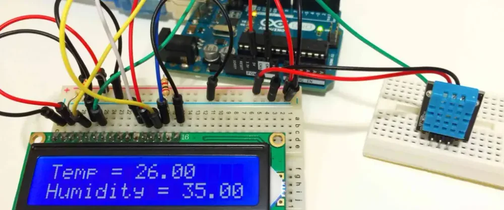
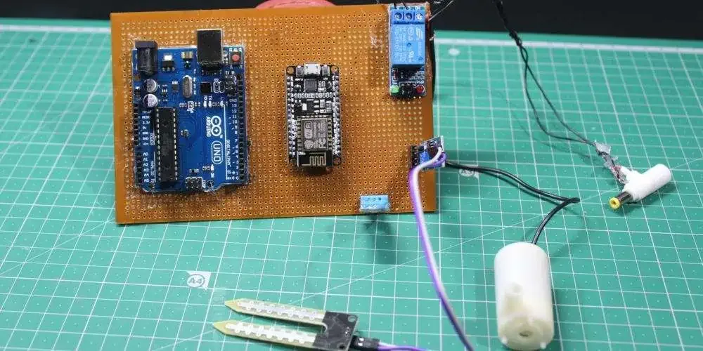
Agricultural IoT hardware measures and communicates conditions in an installation that may be difficult to power, reach or maintain. Its performance depends on the sensor's physical contact, enclosure, cable exposure, energy profile and communication behavior. A working laboratory display is useful development evidence, but it does not establish that the same reading remains meaningful after installation outdoors.
This guide is a field-planning notebook for sensing nodes. It focuses on installation, energy assumptions and serviceability. Irrigation actuation and directional livestock counting have separate pages so their decisions are not hidden inside a broad list of agricultural applications.
Define the site and the decision before choosing the board
Record the physical quantity, measurement location and decision that the information supports. Soil moisture at one depth, air temperature in a shelter and flow in a pipe have different placement and response requirements. Specify the expected range, update interval and what the operator should do when information is unavailable or invalid.
Map the installation conditions that matter: sunlight, moisture, contamination, nearby equipment, cable routes and access for maintenance. Do not reduce the environment to a single outdoor label. A sensor under cover and a probe in soil can impose very different requirements on the electronics and enclosure.
The IoT sensor-selection guide helps connect uncertainty and response to the decision. Keep the selected sensing principle and the installation instructions together. Changing the probe location or mounting can change the meaning of the data even when the PCB and firmware are unchanged.
Treat sensor installation as part of the measurement chain
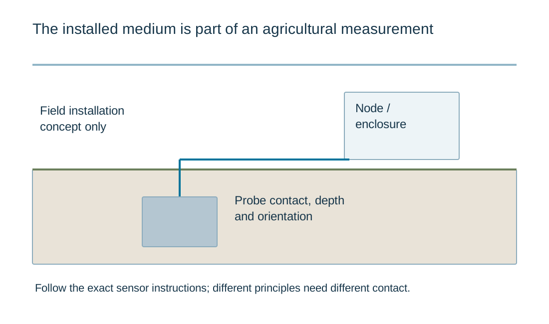
Follow the exact sensor's installation requirements. For soil sensors, contact with the surrounding medium can be important; air gaps and disturbance may affect the result or response according to the measurement principle. METER's installation guidance provides practical examples of why placement and soil contact deserve their own verification step.
Avoid transferring an instruction for one sensor type to all agricultural sensors. A dielectric water-content probe and a water-potential sensor do not measure the same quantity. Their output scales, calibration and installation assumptions should not be treated as interchangeable because both are informally called moisture sensors.
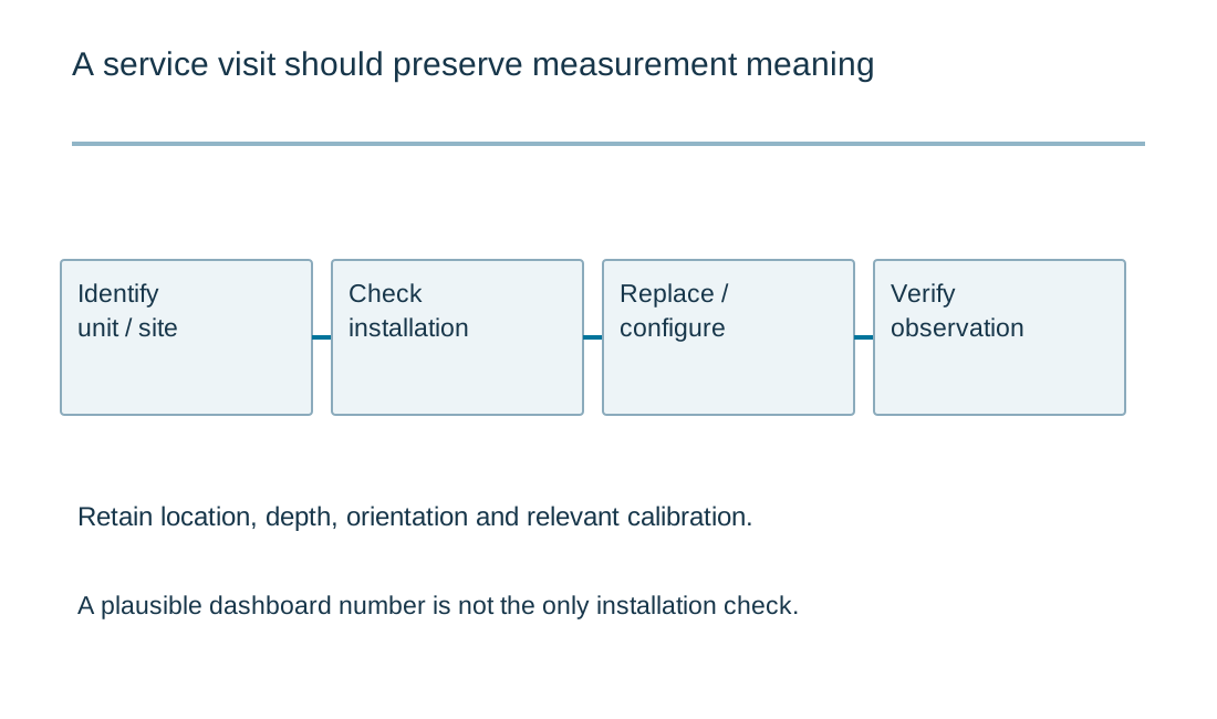
Record location, depth, orientation and relevant calibration or configuration. Define a check after installation and after service replacement. A plausible number on a dashboard should not be the only evidence that the sensor is correctly connected and interacting with the intended physical region.
| Review item | What to establish |
|---|---|
| Field task | Physical quantity, location, update need and action when data are invalid. |
| Installation | Exact sensor instructions, contact, orientation and post-installation check. |
| Energy profile | One boundary, complete states, retries and recovery conditions. |
| Data continuity | Retention, sample time, invalid values and configuration identity. |
| Service and release | Accessible replacement, factory test limits and controlled files. |
Operating-state charge and energy
Operating-state charge and energy
Use the current inputs and keep the assumptions
Load the example to see the units and record format, then clear it before entering your own revision. Example values are illustrative and do not select components or establish acceptance limits. Every field needs an intentional value; a blank number is not treated as zero. For CSV input, retain the header and put one item on each row. Quoted cells can contain commas, but duplicate headers and malformed rows are rejected.
Generate a result only after checking the measurement boundary, operating condition and units. Editing an input invalidates the old result and disables its download until you calculate again. An edited example stays labeled as an example. The report is created locally; it does not upload a design, send an enquiry or populate the Contact form. Attach it manually if it helps explain a requirement. You can contact RAYPCB without completing the tool.
| Input | What to establish before using it |
|---|---|
| Review reference | Use a nonconfidential revision label. |
| Mutually exclusive states · CSV | All currents at the same supply measurement boundary. Durations form one complete repeated cycle. |
| Voltage at that boundary · V | Constant-voltage approximation; upstream converter and battery behavior excluded. |
| Planning interval · h | Assumes the declared cycle repeats continuously; not a battery-life prediction. |
Measure an operating profile that includes difficult days
List the device's states at one supply boundary: waiting, sensor warmup, acquisition, processing, transmission and any relevant retry or recovery period. Keep overlapping activity represented consistently. A profile measured during excellent radio conditions may omit the energy used during repeated connection attempts at the actual site.
The energy worksheet adds current multiplied by time over a complete cycle. It reports average current and charge or energy over an entered interval at a constant voltage. It does not model battery capacity, temperature, aging, solar availability or upstream conversion unless those effects are already represented in appropriate measurements.
Compare a normal profile with a separately declared poor-connectivity or recovery profile. Identify which states can be changed without making the data less useful. Reducing sample frequency is not a universal solution if it removes the events the installation was intended to observe.
Keep energy demand separate from energy availability
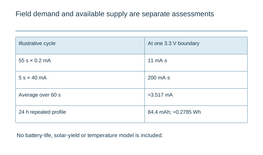
For a simple illustrative cycle, 55 seconds at 0.2 mA and five seconds at 40 mA produce 211 mA·s over 60 seconds, or about 3.517 mA average. At a constant 3.3 V over 24 hours, that corresponds to 84.4 mAh and approximately 0.2785 Wh at that boundary. These are teaching inputs, not a product rating.
A solar or battery system needs a separate supply assessment using the actual component, climate, mounting and service assumptions. Nominal stored energy does not mean all of it is usable at the required voltage and temperature. Keep reserve and recovery requirements explicit rather than multiplying a favorable laboratory current by an optimistic number of days.
If the design includes a valve, the smart-irrigation PCB guide addresses the actuator boundary. A sensing node's low average current does not establish that its supply can operate a valve or tolerate the associated switching conditions.
Design communications and records for interruptions
Define what the node retains when the network is unavailable and how it labels delayed information after reconnection. Separate sample time from receipt time. A delayed value can still be useful for a trend while being unsuitable for a decision that requires current conditions.
Make data loss and invalid measurements visible. A missing record should not silently become zero, and a sensor error should not appear as an extreme but valid physical condition. Keep device identity and configuration with the data so a replaced probe or changed scale can be recognized later.
For installations that count movement, use the livestock-counting PCB guide. Event matching, direction and missed detections need a different verification method from continuous environmental measurements. A shared communication module does not make those application-level acceptance criteria equivalent.
Plan maintenance and manufacturing together
Give a technician a repeatable way to identify the unit, inspect connections and replace the intended service parts. Consider access with the actual enclosure, cables and mounting. A removable cover that exposes fragile internal wiring can turn a routine visit into an unintended electrical or sealing change.
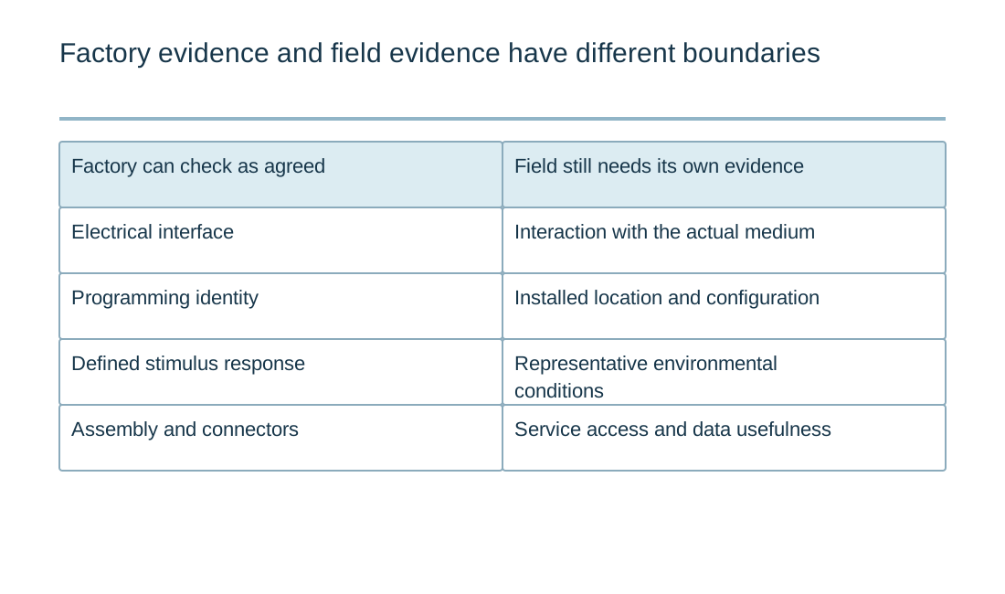
For a manufacturing release, provide the board files, exact sensor and radio modules, enclosure interface, programming requirements and agreed tests. State which checks can occur at the factory and which depend on the installed medium or site. Do not imply that a board-level electrical test validates a complete agricultural measurement.
Send RAYPCB the controlled revision, quantity and the specific unresolved question about fabrication, assembly, connections or test access. Include the field assumptions and an optional energy report if useful. The objective is a maintainable instrument whose data have a defined meaning, with installation evidence and remaining responsibilities visible.
Plan for the site and the service visit
Record how the device is installed, how its sensing surface interacts with the environment and how a technician reaches it. A convenient laboratory position may not represent soil contact, sunlight, animal movement, moisture or the cable exposure at the final location. Keep the installation instructions with the electronics revision.
Review energy demand across normal sampling, communication retries, actuation and recovery. A solar panel or large battery does not eliminate the need to measure those states. Define what data or local behavior is retained when communication is unavailable. Field validation should include independently observed conditions and a clear definition of an error; it should not infer success from a plausible dashboard value alone. Use those observations to revise the electrical, enclosure and maintenance requirements together.
Standards, source context and limits
Use the exact device, system and material documents relevant to the released design. A public reference design demonstrates a particular implementation under its stated conditions; changing its parts, layout, enclosure or firmware creates a different verification task. Standards summaries here identify the type of evidence to request, not every clause of a licensed standard. Component qualification, board workmanship, product validation and regulatory acceptance are separate decisions.
For fabrication scope and the agreed construction requirements, see PCB manufacturing.

