If you are looking to modify or make important changes in your electronic design, it has to be done with an FPGA. The Field Programmable Gate Array (FPGA) is so-named because it allows both the designer and customer to make these changes when needed. When it comes to picking one, it could be a bit difficult. With several brands out there and different FPGAs, you may not be sure of the one to go for.
In this article, you will learn about the Xilinx XA3S200-4PQG208Q FPGA. This is one of the Integrated Circuits (ICs) from Xilinx (now known as AMD). The specifications of the circuit are also discussed to help you understand how its components are designed to work.
The Xilinx XA3S200-4PQG208Q Family
No doubt, Xilinx (now AMD) is one of the leading manufacturers of Field Programmable Gate Arrays (FPGAs). The input in this industry is also evident in the different categories of Integrated Circuits (ICs). The Xilinx XA3S200-4PQG208Q belongs to the Xilinx A family. The Xilinx A family is used to denote the Integrated Circuits (ICs) categorized for use in only automotive applications.
As such, the Xilinx XA3S200-4PQG208Q is primarily used to modify or make important changes in automotive-related electronics.
As a member of the Xilinx Automotive (A) family, the Xilinx XA3S200-4PQG208Q FPGA inherits most of the features. This includes:
The IC inherits an increase in the system gates. It would be recalled that Logic Gates are programmable and are often used to implement or facilitate complex digital computations on electronics.
For the Xilinx XA3S200-4PQG208Q, the number of gates is pegged at 200,000. This is well within the range of 50,000 and 1.5 million system gates that are peculiar to FPGAs in the Xilinx A family.
RAM Bits
One of the major features of the Xilinx XA3S200-4PQG208Q is the increased RAM bits. This feature is the same as every other FPGA under the Xilinx A family. The upgrade comes on the heels of the success recorded with the XA Spartan-IIE family.
The RAM bits on the Xilinx XA3S200-4PQG208Q are 221184.
Technical Specifications of the Xilinx XA3S200-4PQG208Q FPGA
Below are the technical components of the Xilinx XA3S200-4PQG208Q and why they matter:
1. Logic Elements/Cells
Like most Field Programmable Gate Arrays (FPGAs), the Xilinx XA3S200-4PQG208Q includes logic elements/cells. These are usually integrated into the logic blocks and act as a complete block of memory or flip-flops.
The number of logic elements or cells on the Xilinx XA3S200-4PQG208Q is 4,320.
2. Temperature Grade
The Xilinx XA3S200-4PQG208Q operates within the industry-standard AEC-Q100 temperature standard. The minimum temperature is ~40˚C while the maximum operating temperature is 125˚C.
3. Logic Blocks (LABs)
Logic Blocks are an important architecture in a Field Programmable Gate Array (FPGA). They can also be configured or reprogrammed to perform a variety of complex computational functions.
Worthy of mentioning is that the logic blocks are also called Logic Array Blocks (LABs) or Configurable Logic Blocks (CLBs). So, don’t get confused when you see it interchanged that way.
Moving on, the Xilinx XA3S200-4PQG208Q has a total of 480 Logic Array Blocks (LABs). This is quite impressive, considering that an ideal LABs consists of only a few logic cells.
The I/O is a part of the “Hard Blocks” on a Field Programmable Gate Array (FPGA). These hard blocks are used to improve the functionality of the Integrated Circuit (IC) while reducing the area or space required to place the important components.
The Xilinx XA3S200-4PQG208Q’s I/O is 141. With this, the FPGA tends to provide more area for embedded functions while fast-tracking the implementation or deployment of the speed of those deployed functions.
5. Number of Pins & Package Type
A total of 208 pins are integrated into the Xilinx XA3S200-4PQG208Q FPGA. We like to mention that pins are a part of the “analog” functions of an FPGA. The Integrated Circuit (IC) combines both these analog functions and the digital variant for optimum results.
In terms of the pins, the analog functionality is integrated by a programmable slew rate on the output pins. This integration is helpful in many ways, including:
Higher Rate Setting: The programmable slew rate when added to the output pins, helps to fast-track the functionality and the speed of the IC. Ordinarily, in the absence of these pins, the IC would run slowly, especially when it is heavily loaded. But by adding the programable slew rate to the output pins, the speed will be improved via the setting of higher rates upon the heavily-loaded pins operating on high-speed channels.
Prevention of Coupling: Sometimes, the operating rate of the pins on an FPGA can be lower than expected. When this happens, the speed or rate on the lightly-loaded pins will be coupling or ringing. The deployment of the programmable slew rate on the output pins helps to stop this from happening.
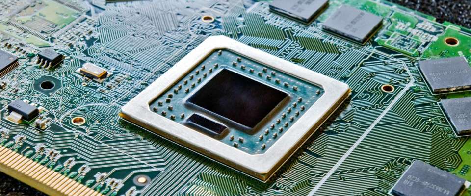
The package type of the Xilinx XA3S200-4PQG208Q FPGA is also impressive. As the device specifications show, it is a plastic-packaged Integrated Circuit (IC). Its package type is Plastic Quad Flat Pack (PQFP).
According to FPGAKey, the Plastic Quad Flat Package (PQFP) is a type of chip-designed packaging used in protecting the components of an Integrated Circuit (IC). By default, this type of packaging has several thin pins on all sides, with the distance between one pin and another very small.
The Xilinx XA3S200-4PQG208Q Field Programmable Gate Array (FPGA) uses a Surface Mount Technology (SMT) design. This is in line with the Plastic Quad Flat Packaging (PQFP) package design that requires the engineer to solder the pins on the side of the chip. The soldering must be done in a way that it is affixed to the motherboard of the FPGA.
Conclusion
The Xilinx XA3S200-4PQG208Q FPGA has an obsolete lifecycle but that shouldn’t be an issue. RayPCB is committed to improving the functionality of your next electronics-related project design. We can help modify or make important changes to your devices so that the Xilinx XA3S200-4PQG208Q would function optimally when integrated into these devices.
This Integrated Circuit (IC) spots additional enhancements to the Xilinx Spartan-3 family, combined with advanced process technology to deliver excellent bandwidth and optimal functionality.
Contact us today to process your next Field Programmable Gate Array (FPGA)-powered project.
Field Programmable Gate Arrays (FPGAs) are used to reprogram the components of a circuit board. These gate arrays function via semiconductor devices that are based on Configurable Logic Blocks (CLBs). This would, in turn, be used to establish the connection to programmable interconnects.
The Xilinx XA3SD3400A-4CSG484I FPGA is a type of circuit board part from the stable of Xilinx (AMD). It is an automotiveIntegrated Circuit (IC) designed for use with automotive electronic devices.
Like other Field Programmable Gate Arrays (FPGAs), the Xilinx XA3SD3400A-4CSG484I can be reprogrammed or remodeled to fit into the desired functionality of an electronic device after its manufacturing.
Category of the Xilinx XA3SD3400A-4CSG484I FPGA
The Xilinx XA3SD3400A-4CSG484I is an Integrated Circuit (IC) with an embeddable design. This allows for easy installation or integration into any automotive electronic application.
The operating temperature of a Field Programmable Gate Array (FPGA) has to do with the minimum and maximum temperature for which the IC can operate.
The Xilinx XA3SD3400A-4CSG484I, being a part of the Xilinx Spartan 3A family, takes a leaf from the extended-temperature grade of FPGAs in that family. Its temperature rating is (~40˚C – 100˚C). This way, the components inside the Integrated Circuit (IC) wouldn’t underperform due to limited temperature or be exposed to over-performance because of excess temperature.
Number of Gates
The gates refer to the programmable gates used for enabling complex digital computations in a Field Programmable Gate Array (FPGA).
The Xilinx XA3SD3400A-4CSG484I has one of the highest numbers of gates with an estimation of 340,000. Ideally, FPGAs under the Xilinx Spartan 3A family have gates between 50,000 and 1.5 million.
Voltage Supply
The voltage of the Xilinx XA3SD3400A-4CSG484I is also regulated. This goes a long way to prevent the Integrated Circuit (IC) from either disrupting the entire functions of the board components or causing malfunctions.
The rated voltage supply is between 1.14 volts and 1.26 volts. Of course, you and the engineer can test the IC to be sure the power supply doesn’t fall below or go above this before deploying the semiconductor.
While there are no single elements or components for a Field Programmable Gate Array (FPGA); some cannot be disposed of. One of such is the logic cells or elements. These elements comprise a large number of flip-flops and can double as a complete block of memory.
The logic elements/cells on the Xilinx XA3SD3400A-4CSG484I are significantly higher with an estimate of 53,712.
Input/Output
The Input and Output (I/O) of the Xilinx XA3SD3400A-4CSG484I is 309. Generally, the I/O of a Field Programmable Gate Array (FPGA) are dedicated processors that facilitate self-executing instructions in the Integrated Circuit (IC).
The Xilinx XA3SD3400A-4CSG484I’s I/O is significantly higher than some of the other FPGAs from the Xilinx Spartan 3A family. Xilinx recommends that the ideal range for the I/O in the Integrated Circuits (ICs) should not be above 487 I/O pins.
Mounting Type
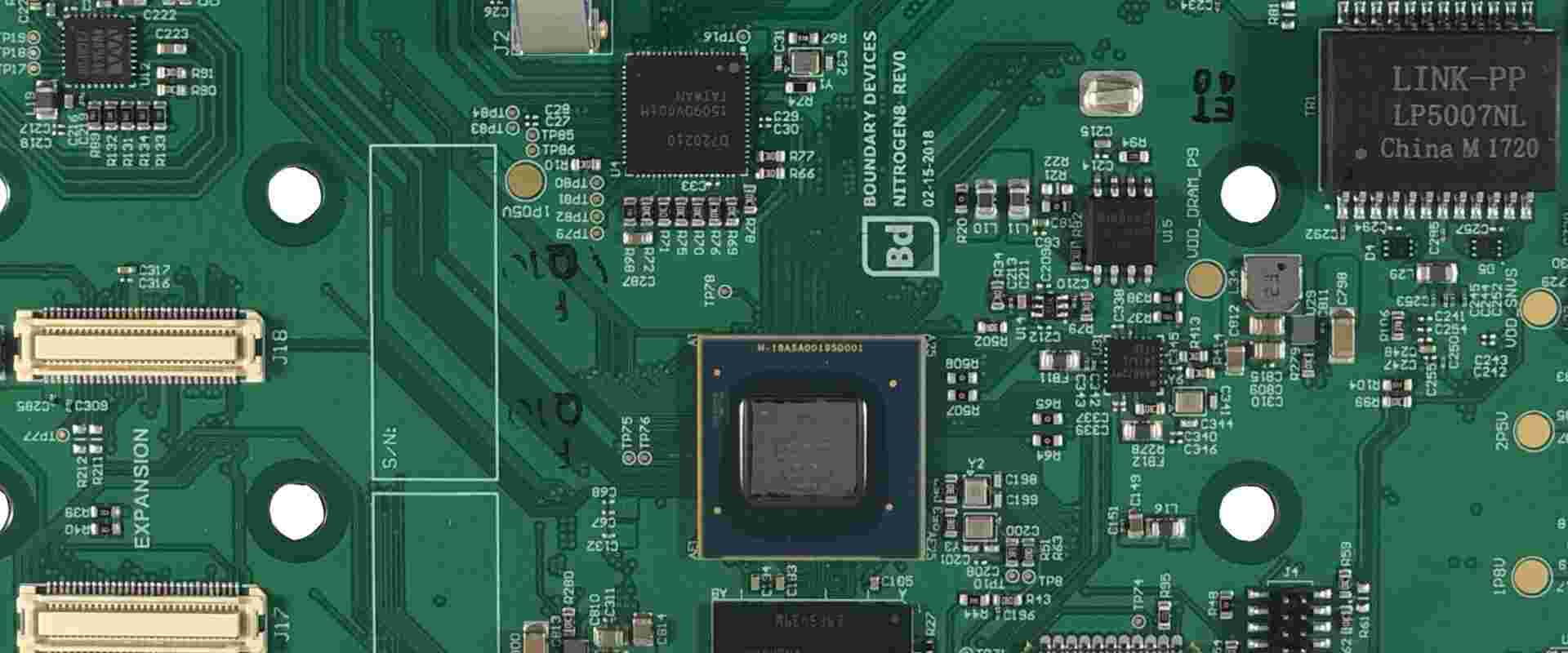
The Xilinx XA3SD3400A-4CSG484I uses the Surface Mount Technology (SMT) for placing the components on the Integrated Circuit (IC). The SMT design is adjudged to be one of the best, especially when simplicity is considered.
Package & Case
The Xilinx XA3SD3400A-4CSG484I uses the “Tray” package. According to Digi-Key, the Tray FPGA package is a JEDEC matrix standard tray that measures 12.7 by 5.35. It also allows for the vertical passage of air, as enabled by the integration of slots in the tray.
The JEDEC tray can be manufactured with both aluminum and plastic, but plastic is more common.
The Integrated Circuit (IC) uses the 484-FBGA case. This type of case is categorized under the Ball Grid Array (BGA) Integrated Circuit (IC) package type. Under the Ball Grid Array (BGA), the most popular are:
Wondering if the Xilinx XA3SD3400A-4CSG484I Integrated Circuit (IC) is one of the best Field Programmable Gate Arrays (FPGAs)?
Here are some of the benefits of designing your next automotive-related electronic project with it:
1. Improved Clocking Functions
The functions of the clock in the Xilinx XA3SD3400A-4CSG484I FPGA are improved. This is also one of the major improvements in the functionalities of the Field Programmable Gate Arrays (FPGAs) in the Spartan 3A family.
First, it has a high-resolution phase shifting that combines with the Digital Clock Manager (DCM) to provide:
Phase-shifting clock signals
Self-calibration
Clock delaying, division, and multiplication.
Excellent distribution of fully digital clocking solutions.
Second, the Xilinx XA3SD3400A-4CSG484I clocking function features up to four (4) Digital Clock Managers (DCMs). These include:
125 MHz maximum clocking frequency.
Clock skew elimination.
Frequency synthesis.
2. Automotive Applications
The Xilinx XA3SD3400A-4CSG484I is used primarily for automotive applications. As a part of the Xilinx Spartan 3A family, the IC is used in low-cost and high-volume solutions for automotive applications. It is also useful in high-performance logic solutions for the same applications.
The Input and Output (I/O) performance of the Xilinx XA3SD3400A-4CSG484I FPGA is impressive. It has a 309 I/O rating, which promises a transfer speed of up to 622 megabytes (MB) of data transferred per second.
At such a fast pace, the I/O can transfer a substantial amount of data to facilitate the execution of the set functions or instructions in the IC.
4. Look-Up Tables (LUTs)
The Look-Up Table (LUTs) are not made obvious in the technical specifications of the Xilinx XA3SD3400A-4CSG484I. Yet, they are a part of the functionalities of the IC.
The Look-Up Tables (LUTs) are integrated into the Random Access Memory (RAM) of Xilinx XA3SD3400A-4CSG484I. these combine with the Configurable Logic Blocks (CLBs) to store and implement/deploy logic functions. These elements can also be configured to function as either latches or flip-flops.
Final Words
The Xilinx XA3SD3400A-4CSG484I is used by engineers and consumers looking to improve the functions of their automotive electronics. If this is what you are looking for, do not hesitate to contact RayPCB. We offer both professional advice and smart engineering to help you get the most out of your Xilinx XA3SD3400A-4CSG484I Integrated Circuit (IC).
The significance of PCB material in technology and engineering is necessary. This is because of its great use in consumer devices like smartphones, as well as infrastructure that ensures the functioning of these devices.
This is a very good reason why there is a need to choose the right PCB material for your needs. Have you been searching for one? Then, we have a good recommendation for you and that is the Doosan DS-8502LC PCB Material. If you wish to know more about this PCB material with high reliability, please continue reading.
What is the Doosan DS-8502LC PCB Material?
The Doosan DS-8502LC PCB Material is a reliable material for printed circuit boards due to its great features. These include its high temperature for glass transition, low dissipation factor, low dielectric constant and low coefficient of thermal expansion.
Furthermore, the Doosan DS-8502LC PCB Material is useful in different applications, which includes SLP for Smartphones and EFSSD. The reliability of this material cannot be questioned after all these great features it possesses.
What are the Properties of the Doosan DS-8502LC PCB Material?
The properties of the Doosan DS-8502LC are categorized into three. These include thermal properties, mechanical properties, and electrical properties. Also included here are other properties of this material. Please join me as we quickly consider them.
Thermal Properties
The Doosan DS-8502LC has a glass transition temperature (DMA) of 260 degrees Celsius. This is the temperature at which glass transition occurs and it is usually lower in contrast to the melting temperature of the material’s crystalline state. At this temperature, the material transforms from its ductile look to one that is brittle and hard.
Also, the decomposition temperature of this material is 430 degrees Celsius. This value indicates the temperature at which the material will decompose chemically. It involves an endothermic reaction. Furthermore, its T-288 value is greater than 120 minutes.
At the X.Y axis, it has a coefficient of thermal expansion (CTE) of 10/9 ppm/℃. Also, at the Z axis, the CTE is 20/120 ppm/℃. In addition, it has a thermal conductivity of 0.6 W/m·k. The coefficient of thermal expansion (CTE) is the rate at which a printed circuit board material expands while it heats. In addition, the maximum operating temperature is 130 degrees Celsius, while the Z expansion is 1.2%.
Mechanical Properties
The following are the mechanical properties of the Doosan DS-8502LC PCB Material. The Doosan DS-8502LC has a Young’s modulus value of 30 GPa. This value indicates how this material can easily deform and stretch.
Also, its Flexural strength is 30 Mpa, which signifies the ability of the material to resist changes or deformation anytime it is under load. Furthermore, its storage modulus is 29 GPa and lastly, it has a peel strength of 0.75 kgf/cm. Generally, this value helps in measuring the material’s bond strength, most likely an adhesive
Electrical Properties
The electrical properties of the Doosan DS-8502LC PCB Material include the following. It has a dielectric constant of 3.5 at 10GHz. Also, at 10GHz, it has a Df value of 0.007.
Both values (dielectric constant and dissipation value) are low, which makes them suitable and reliable in different applications. Dielectric constant has to do with a quantity that measures a material’s ability to store some electrical energy in a given electric field.
This value indicates the material’s inefficiency to act like an insulator. Furthermore, this material has a low dissipation factor; therefore, it is very efficient as an insulating material.
Other Properties
Other physical properties of the Doosan DS-8502LC PCB Material asides from the ones mentioned above. These include the water absorption and flammability. This PCB material has a flammability rating of V-0. This means that burning has to stop in 10 seconds. Also, its water absorption is at 0.15%. Water absorption is the quantity of water that the material absorbs.
Below are the main features of the Doosan DS-8502LC PCB Material
Ultra High glass transition temperature (Tg)
The temperature for glass transition is that temperature at which a material such as the Doosan DS-8502LC PCB Material transforms from its initially ductile nature to something that is brittle and hard. Furthermore, the Doosan DS-8502LC PCB Material has a high Tg. This once again proves that this material has high reliability.
Low Coefficient of Thermal Expansion (CTE)
One great feature of the Doosan DS-8502LC PCB Material is its low coefficient of thermal expansion. This property (CTE) indicates the manner at which a material will expand for every 1 degree centigrade increase in temperature. This means that the shape of the material will not be affected much when there’s a change in temperature
Low Dissipation Factor (Df)
Dissipation factor helps in measuring the insulating material’s inefficiency. This property also reveals how much or how effective a material will be in different environments and applications. This also indicates a material’s inefficiency to act like an insulating material or hold energy. Doosan DS-8502LC PCB Material has a low dissipation factor. This means that its insulator system is more efficient.
Low Dielectric Constant (Dk)
A material’s dielectric constant is very necessary for impedance considerations and signal integrity. These factors are very important and critical for high electrical performance. The Doosan DS-8502LC PCB Material has a low dielectric constant, which makes it very useful for high power and frequency applications. This helps in reducing any loss of electric power.
The following are areas where you can apply the Doosan DS-8502LC PCB Material.
SLP for Smartphones
Solid device for server
Conclusion
We hope we have been able to explain what the Doosan DS-8502LC PCB Material is, its properties, as well as its applications. It is a reliable material for printed circuit boards due to its great features. These include its high temperature for glass transition, low dissipation factor, low dielectric constant and low coefficient of thermal expansion. If you have some questions after reading through this article, feel free to ask us.
PCB materials are a very essential part of a finished printed circuit board. They serve as the foundation of PCBs. When fabricating a PCB, it is important to select materials that suit the requirements of the intended application.
For instance, if a PCB meant for high performance applications needs high-quality PCB materials. The Doosan Middle Tg DS-7402 is a good substrate material for PCB fabrication. In this article, we will be discussing Doosan Middle Tg DS-7402 PCB material.
What is Doosan Middle Tg DS-7402 PCB Material?
DS-7402 is a middle glass transition temperature PCB laminate with great thermal and mechanical properties. Also, this PCB material is a great option for high performance PCBs. Doosan Middle Tg DS-7402 PCB material features a low CTE value at X and Y-axis. Also, it features a low dissipation factor which makes it resistant to heat.
Doosan Middle Tg DS-7402 PCB material is a good insulator system. Therefore, this material is ideal for PCBs used in high temperature operating environments. This lead-free PCB material features CAF resistance. Therefore, this makes Doosan Middle Tg DS-7402 a safe material for PCB fabrication. Also, this material is free of halogen, phosphorus, and antimony.
When it comes to performance, Doosan Middle Tg DS-7402 is highly ranked. This PCB material has excellent properties that contribute to its performance.
Properties of Doosan Middle Tg DS-7402 PCB Material
Thermal properties
The glass transition temperature of this material is 165 degrees Celsius. This is a middle Tg value for a PCB material.
The decomposition temperature of Doosan Middle Tg DS-7402 is 380 degrees Celsius at 5% weight loss. This indicates a high decomposition temperature. Therefore, this material won’t easily decompose chemically.
At T-288, the delamination time of this material is greater than 15 minutes.
The CTE value of this material at the X and Y axis is 15 and 14 ppmo/C respectively. However, the CTE at Z-a1 and Z-a2 is 38 and 230 ppmo/C respectively.
Thermal Analysis Techniques for Doosan Middle Tg DS-7402
Thermal performance is an essential part of PCB materials. A material that features great thermal reliability and performance adds value to a PCB. Therefore, it is important to analyze the thermal performance of a PCB material. However, several thermal analysis techniques are used for Doosan Middle Tg DS-7402.
Thermomechanical analysis
This technique determines how the physical properties of a material changes in relation to temperature. Therefore, it evaluates the changes in Doosan Middle Tg DS-7402’s appearance when exposed to varying temperatures. Also, TMA determines physical properties like density, physical dimensions, and volume of DS-7402. It evaluates how these properties change in relation to temperature and applied force.
TMA is a common thermal analysis technique. Also, this technique measures dimensional changes of a material. For instance, it can measure the CTE of Doosan Middle Tg DS-7402. Also, it can evaluate the Tg of a material.
Dynamic mechanical analysis
Popularly known as DMA, it is ideal for evaluating viscoelasticity of a material. Viscoelasticity refers to the combination of elasticity and viscosity. Also, DMA evaluates the resistance of Doosan Middle Tg DS-7402 to deformation under vibration. This means, it looks at how a material bends and stretches when in motion. Also, this technique is ideal for determining Tg. Changes in temperature and stress can affect the thermal property of a material.
Thermogravimetric analysis
This determines how temperature impacts the weight of Doosan Middle Tg DS-7402 PCB material. Also known as TGA, this thermal analysis technique is very common. It evaluates how weight loss relates to temperature in a controlled environment. Before testing, the material is properly weighed at room temperature. After that, the analysis monitors the changes as the material exposes to an amount of heat.
Doosan Middle Tg DS-7402 PCB material has a lot of features which are beneficial to PCB fabrication. These features serve as benefits.
Environmentally friendly
Doosan Middle Tg DS-7402 is free of halogen and phosphorus. Therefore, it is an environmentally friendly material. Also, this PCB material doesn’t contain alimony.
Anti-CAF property
One of the amazing features of this material is its resistance to CAF. This serves as a great benefit for PCB fabrication. Conductive anodic filament (CAF) usually happens between adjacent vias in a circuit board. Also, it is a major concern in PCB fabrication. However, Doosan Middle Tg DS-7402 is resistant to CAF.
Great thermal performance
Doosan Middle Tg DS-7402 features exceptional thermal properties. Therefore, this material is reliable and performs well. For example, it features middle glass transition temperature and low Z-axis CTE. Also, these thermal properties impact the thermal performance of this material.
UL-94 flammability
This material adheres to UL 94 flammability standards. Doosan Middle Tg DS-7402 is UL-94 V-0.
Applications of Doosan Middle Tg DS-7402 PCB Material
Doosan Middle Tg DS-7402 is commonly used in several applications. This PCB material serves as a great alternative for conventional lead-free FR-4. Also, this PCB material is ideal for use in consumer electronics. For example, it is widely used in computers and mobile phones. In addition, this material is available in A/V devices.
It is a great option for these applications because of its benefits and properties. Also, this material is specifically designed to meet the needs of high performance applications.
Conclusion
This article explains every important detail about Doosan Middle Tg DS-7402. This PCB material features distinct electrical, mechanical, and thermal properties.
The type of material used for PCB fabrication determines its PCB performance. In those days, FR4 material was a common material. However, with high performance designs, it is very crucial to use the appropriate laminate. Therefore, it is advisable to use a material that features excellent properties. This helps to ensure great performance. In addition, this helps to enhance functionality in applications
The environmental stability of a material is an important factor to consider when choosing a material. This article focuses on the Panasonic MEGTRON M R-5735 laminate and what it offers.
Panasonic MEGTRON M R-5735 laminate is a low loss multilayer circuit board material. Also, it is a heat resistant material ideal for data transmission of router and server at high-end applications.
This multilayer PCB material enhances greater-capacity data transmission. Therefore, this improves the 5G mobile communication systems. Panasonic MEGTRON M R-5735 laminate is a halogen free PCB material. This means that it features no halogen constituents. Therefore, it is ideal for the environment.
With a low dissipation factor and dielectric constant, this material offers the best performance. Also, this material reduces signal loss when used in applications. Signal integrity is a concern for most PCBs used in the communication system. The dissipation factor of this material is lower than that of MEGTRON R-5375.
Also, Panasonic MEGTRON M R-5735 laminate features great mechanical and thermal properties. These properties contribute to the high performance of this material in extreme temperatures. Asides its high resistance to heat, this material enhances data transmission.
Properties of Panasonic MEGTRON M R-5735 Laminate
Panasonic MEGTRON M R-5735 laminate has some distinct properties:
Low water absorption rate
The water absorption rate of this material is 0.14%. This indicates a low water absorption rate. Also, low water absorption rate contributes to its thermal performance. This means that this material can hardly absorb water when immersed in it.
Low dissipation factor
The dissipation factor of this laminate is extremely low. Also, Panasonic MEGTRON M R-5735 features a Df value of 0.005 and 0.007 at 1 GHz and 10 GHz respectively. Dissipation factor measures the degree of loss when electricity in an insulator system is discharged. Very low Df materials are a better insulator.
The Td value of Panasonic MEGTRON M R-5735 is 360 degrees per Celsius. With a high decomposition temperature, this material can function well under a high temperature without decomposing chemically. A Td value of 360oC means this material will start decomposing chemically when subjected to a temperature above this degree.
High glass transition temperature
The glass transition temperature of this material is 195oC at DSC. At DMA, this value is 210oC. The Tg value changes to 185oC at TMA. Tg offers different results when measured with different thermal analysis. However, the Tg of this material is high irrespective of the thermal analysis technique used.
Low dielectric constant
The dielectric constant of Panasonic MEGTRON M R-5735 is very low. Also, this laminate features a Dk value of 3.9 at 1 GHz and 10 GHz. It maintains a stable Dk across a wide frequency and temperature range. This is a great advantage for PCB fabrication.
Low CTE value
The Z-axis CTE value of this material is 31 ppm/oC. Therefore, this material can hardly expand in size when exposed to different thermal conditions.
Advantages of Panasonic Halogen-free MEGTRON M R-5735 Laminate
Low loss material
One of the major concerns in high frequency PCB application is signal loss. Therefore, it is vital to use material that features low transmission loss. Also, this low loss material ensures high data transmission. Also, Panasonic MEGTRON M R-5735 laminate is ideal for use in the communication industry.
Environmentally safe
Halogen is a toxic material for PCB fabrication. Also, it is very harmful to humans and the environment. Panasonic MEGTRON M R-5735 laminate is free of halogen constituents. Therefore, it is environmentally safe. Halogen constituents include bromine, fluorine, and chlorine. These substances are very dangerous.
High heat-resistance
Panasonic MEGTRON M R-5735 laminate resists high heat. This helps to enhance reliable operation. Also, this multilayer PCB material offers high reliability in high temperature environments. The thermal properties of this material contribute to this feature.
UL 94 V-0 flammability
One of the benefits of this PCB material is that it meets the UL94 V-0 flammability standard. Therefore, Panasonic MEGTRON M R-5735 laminate features flame retardation. Also, it meets the specifications of other industry standards.
Great performance
This is another benefit of using Panasonic MEGTRON M R-5735 laminate for PCB fabrication. Panasonic MEGTRON M R-5735 laminate performs well both thermally and electrically. Also, this material is electrically stable over a wide frequency range.
The Effect of Low Dielectric Constant on Panasonic MEGTRON M R-5735 Laminate
A material’s dielectric constant has a huge effect on its performance. It measures a material’s capacity to store electrical energy. Also, materials commonly used in the communication need to have low dielectric constant. In addition this value should be stable over a wide frequency range. The dielectric constant is an electrical property that determines signal integrity.
A material’s dielectric constant changes with frequency. A low dielectric constant enhances high-frequency performance. This feature has a great impact on the performance of Panasonic MEGTRON M R-5735 laminate.
Panasonic MEGTRON M R-5735 laminate is widely used in communication systems. This is due to its low dielectric constant. With this low Dk value, this material enhances signal transmission. Also, the low dielectric constant reduces signal loss. Low dielectric materials are more efficient. When signal integrity and impedance control are crucial, a low dielectric material is the right choice.
In addition, Panasonic MEGTRON M R-5735 laminate offers a low dissipation factor. The low Dk and Df value contribute to the electrical performance of this material. Therefore, this material is ideal for use in applications that demand high frequency.
Conclusion
This article has discussed how Panasonic MEGTRON M R-5735 laminate impacts high frequency PCBs. Having read this article, we hope you have more knowledge about this laminate.
Printed circuit boards are essential for electronics manufacturing. This board serves as a framework for most electronic devices. Therefore, it is very important to utilize efficient materials for these boards. There is a wide range of PCB laminates used for PCB fabrication. With the development in the PCB industry, there is a rising demand for high reliability multi-layer materials. In this article, we will be discussing the Panasonic HEPER R-1755E PCB material.
What is Panasonic HEPER R-1755E PCB Material?
Panasonic HEPER R-1755E PCB material is a heat resistant multilayer PCB material. Also, this laminate features a low CTE and high decomposition temperature. This PCB material is greatly ideal for use in high performance applications. In addition, this material features high heat resistance. This lead-free soldering compatible material offers exceptional benefits.
Panasonic HEPER R-1755E PCB material offers great laminate processability. This PCB material adheres to some standards in the PCB industry. For instance, it is RoHS compliant. Also, it is safe for use in PCB fabrication. It is a non-toxic PCB material. This multilayer PCB material meets the specification of IPC 4101/126/97/98/99/101. Therefore, it is a highly reliable PCB material.
Panasonic HEPER R-1755E PCB material guarantees great performance and functionality. Also, it offers great reliability. This material can survive varying temperature degrees because of its high heat resistance. Panasonic HEPER R-1755E PCB material maintains a great balance between cost and performance.
Properties of Panasonic HEPER R-1755E PCB Material
Panasonic HEPER R-1755E features great mechanical, thermal, and electrical properties. These properties contribute to the performance of this laminate. Also, these properties are suitable for high frequency applications.
High thermal decomposition temperature
The decomposition temperature of Panasonic HEPER R-1755E is 370 degrees Celsius. Also, this thermal property describes the temperature at which Panasonic HEPER R-1755E decomposes chemically. The decomposition temperature of PCB materials varies. When this material is exposed to a temperature above 370oC, it will decompose.
Low glass transition temperature
The glass transition temperature of this material is 133 degrees Celsius. This is a very low glass transition temperature. Also, this is an important property of a PCB material. Glass transition temperature indicates the temperature at which a material becomes unstable.
The dielectric constant of Panasonic HEPER R-1755E PCB material is 4.6 at 1 GHz. Also, this electrical property contributes to low signal loss. A low dielectric PCB material is suitable for high power applications. This is because it reduces electric power loss.
Low dissipation factor
The dissipation factor of a material measures its inefficiency to act as an insulating material. Panasonic HEPER R-1755E is 0.013 and 0.019 at 1 GHz and 10 GHz. Low dissipation factor indicates the efficiency of the material. Therefore, Panasonic HEPER R-1755E PCB material is an efficient insulator system.
Low water absorption
The water absorption rate of a PCB material is very essential for a PCB performance. Also, a PCB material with a low water absorption rate contributes to thermal performance. The water absorption rate of Panasonic HEPER R-1755E is 0.11%.
Low coefficient of thermal expansion
The CTE of this material is very low at both X and Y axis. Also, it maintains a low Z-axis CTE value. The CTE at Z-axis is 42.
Panasonic HEPER R-1755E features excellent benefits. Also, these benefits make this material ideal for use in network equipment. Therefore, the advantages of Panasonic HEPER R-1755E include:
High heat resistance
Panasonic HEPER R-1755E highly resists heat. Also, this material can withstand extreme temperatures. Therefore, this material is ideal in applications that demand high performance. Panasonic HEPER R-1755E PCB material features low CTE and high decomposition temperature. These properties contribute to its high level of heat resistance.
Great through-hole reliability
There are several factors that contribute to the reliability of a through hole. Also, through-hole reliability is a major concern for multi-layer PCBs. Therefore, Panasonic HEPER R-1755E is an ideal material for multilayer boards. This is because this material offers excellent through-hole reliability.
Industry approval
This is another benefit of Panasonic HEPER R-1755E PCB material. This material meets the specifications of some PCB standards. For instance, this material is RoHS compliant. Also, Panasonic HEPER R-1755E meets the specification of IPC/4101. This indicates the functionality of this material.
Great CAF resistance
Conductive anodic filament (CAF) is a major concern in PCB fabrication. This PCB material resists CAF. Therefore, it is ideal for use in high frequency and high performance applications.
Lead free soldering compatibility
This laminate is compatible with lead-free soldering. Also, lead-free soldering is highly recommended for PCB fabrication. This type of soldering has a greater melting point. The use of lead soldering isn’t safe. Therefore, the PCB industry prohibits the use of such soldering.
Applications of Panasonic HEPER R-1755E PCB Material
Panasonic HEPER R-1755E PCB material is commonly used in the automotive industry. This PCB material is ideal for use in automotive components. Also, this material features great thermal and mechanical properties that are ideal for designing automotive components. However, this PCB material is also used in industrial applications.
Electrical appliance
Panasonic HEPER R-1755E PCB material is commonly used for designing electrical appliances. Also, this PCB material is ideal for use in this application due to its performance. Panasonic HEPER R-1755E PCB material offers low signal loss.
Panasonic HEPER R-1755E PCB material is ideal for use in the automotive industry. This PCB material is suitable for designing automotive components. Also, it is widely used for designing electric cars. The automobile industry keeps experiencing new development. One such development is the introduction of electric cars. Therefore, the use of advanced PCB material is highly recommended.
Industrial application
Some devices used in the industries require the use of high performance PCB material. Therefore, Panasonic HEPER R-1755E PCB material is widely used in this application. Also, this laminate offers great benefits and properties essential for designing industrial devices.
Conclusion
HEPER R-1755E PCB material is one of the best materials by Panasonic. Panasonic is well-known for delivering high performance material for PCB fabrication. In this article, we have discussed one such product.
Light-emitting diodes are small devices used in many different applications, even for standard light bulbs. In recent years, LED SMTs have changed how we do many things. Surface Mount TechnologyLED lights have revolutionized how people do things at home, and made it easier for companies to do business. LED SMT (surface mount LED) is just another version of surface mount technology (SMT). Other SMT uses are through via-hole versions but not as popular as surface mount.
Surface Mount Technology LED lights are very different in appearance from the standard light bulbs that people know today. The main difference is that they contain an LED chip instead of a filament. As a result, the film warms up to a certain point and produces light. A chip is on many LEDs visible when you turn on the light.
Surface mount technology (SMT for short) is an electronic circuit board where you place the LEDs on the board itself rather than on a separate chip. You can then easily and quickly replace the LED chip…
Surface mount technology is a way to make circuit boards smaller and more compact. Traditionally, to do this, you would add through-hole components to the boards, but then there would be wires that had to connect multiple through-hole components. This means there is an added space on the board, and it generally adds to cost too. Surface mount technology enables you to replace multiple through-hole components with a single surface mount component, thus enabling the use of smaller boards and leading to more compact designs.
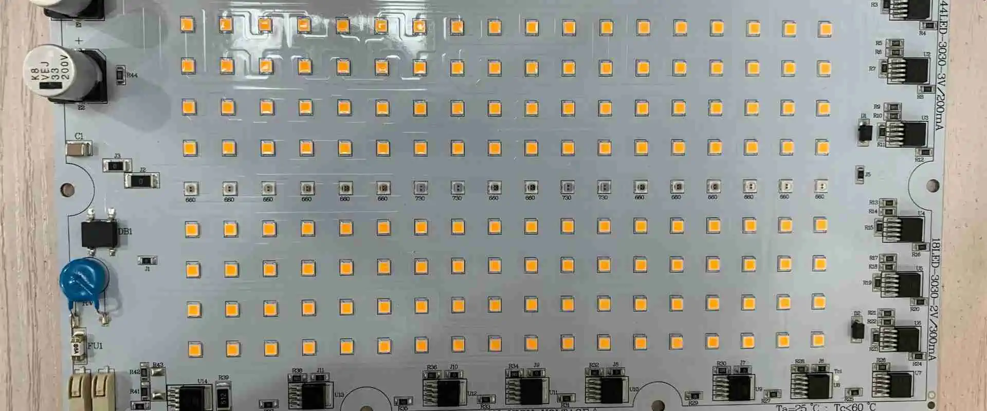
When it comes to a LED SMT strip, each LED is connected to a tiny circuit board using a wire. This type of SMT is found in most consumer electronics and will be the most common type of SMT. The rectangular LEDs are sold as strips of lights you can run along the bottom of the inside of your cabinets or bookcases. The advantage of using an SMT LED strip is that it is solid and doesn’t take up much room.
Advantages of LED SMT
The main advantage of LED SMT lights is that they are very energy efficient. As a result, they use less electricity than standard light bulbs, which can cause problems if we use too many lights in a home. They also don’t give off as much heat as filament lights, making them safer for use around pets and children. They are also very light, making them easy to carry from place to place.
SMT makes it easier to make smaller boards. A smaller board equals less cost per square inch, meaning it’s cheaper for the end-user. Also, you can quickly and easily do the switch between through-hole and surface mount, making it easier for engineers to design their products.
There is a reduction of lead-free and RoHS components. This reduces the cost for manufacturers to make their products and saves on valuable resources.
SMT doesn’t rely on human assembly for installation, making for a more consistent product. In addition, this means you can standardize your design more effectively.
SMT technology makes it easier to use surface-mount LEDs. Some smaller components are either unavailable for through-hole or are more expensive. Using SMT, you can use a variety of small surface-mount LEDs instead of only one type of via-hole LEDs.
SMT LEDs are smaller, cheaper, and you can place them in more compact areas. Therefore, you save money and space. They are also easier to produce and do not need complex wiring processes…
We use LED SMT in many different things, from household items like light bulbs to medical devices and electronics. In addition, the uses for LED SMT have expanded as time goes by, which makes it simple for people to learn more about the latest lighting technology available.
LED SMTs are used to replace an incandescent or fluorescent lamp. They have provided light without the heat or the nastiness of Mercury, which is considered a toxic element in a fluorescent lamp. While they do put out heat and you need some way to ventilate a room, they provide much less heat than other types of lighting…
SMT LED Bulbs
You can use SMTs to make beautiful lights. You can make LEDs into anything, as they have so many different shapes: They are more reliable than most other types of light sources. A surface mount LED will often give off much more light than a lamp with the same power rating. You don’t need to plug in your LEDs for them to work, and the circuitry of each LED is very small, so your circuit board won’t lose too much space for the purposes of wiring it up.
How do you surface mount LED lights?
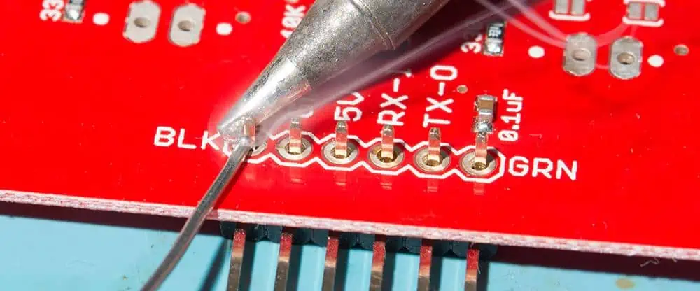
There are many different ways to surface mount LEDs, but we will cover the basics. Some people prefer to have PCBs with multiple layers, but most end-users and manufacturing houses prefer to have their boards as single-sided. If your PCB only has one layer, you can manually attach the LEDs to the board by soldering the leads to the PCB traces. If your board is double-sided and has multiple layers, you can either use surface mount technology to route out holes where you want your LEDs or try stuffing them from underneath.
There are several different ways that you can solder LED SMT to a circuit board or piece of plastic. For example, you can use a soldering iron to melt the solder onto the surface of the light, or you can use a hot glue gun to attach the pieces together. In some cases, one can attach the LED SMT by using a heated wire instead. The best way to install your LED SMT is to find out which method the manufacturer recommends.
The first thing you need to know how to do to solder an LED is how electricity works. In this case, meaning simply how electricity flows…
You will need experience with electronics to continue. You need to know about the parts of the circuits, such as resistors and capacitors. For those who have little experience with electronics but wish to learn, I suggest attempting to solder a basic circuit before getting into SMTs…
There are several different types of LED SMT that you can use to light up a room or illuminate something in your home. The type of light you’re trying to achieve will determine the type you need to use. The most popular types are:
Dimmer switches: The dimmer switches in LED bulbs operate well with minimum wattage
Color LED: Available in 3 options: warm white, cool white, and daylight LEDs.
LED Tubes good for lighting: They substitute fluorescent tubes and are available in various sizes to offer LED miniatures.
SMD LED: They have additional reliable brightness for your household or office.
COB (chip on board) LED: Offers strong controlling light with high productivity.
Graphene LED: Cheaper as compared to standard bulbs and uses 10% lesser energy.
Inorganic Traditional LEDs
Organic LEDs
Conclusion
Learning about LED SMT lights is very important for anyone who wants to know how to do things today. The lights are easy to use, making them a good choice for anyone new at home improvement. If you want to choose the best type of light, it’s a good idea to look at the available different types of SMT. You shouldn’t be afraid of trying out new things to learn more about technology. The Internet makes it easy for you to find bulk LED SMT discount.
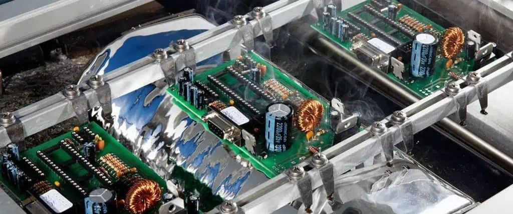
Soldering is a critical process in the assembly and manufacture of electronic devices and PCBs. It provides both mechanical and electrical connections between component leads and pads. While manual soldering has been used for decades, automation through machines and robots has become essential for modern high-volume production.
This article will compare manual and automated soldering approaches across criteria like process capabilities, quality, costs, applications, advantages, and disadvantages. We will examine popular techniques including manual iron soldering, wave soldering, selective soldering, and automated soldering robots. Understanding the strengths and limitations of each method helps determine the best fit for a particular manufacturing environment and product.
Manual soldering relies on a human operator to directly form joints using a hand-held soldering iron or soldering station. Let’s look closer at manual techniques.
Soldering Irons
The most basic manual approach uses simple electrical or battery-powered soldering irons.
Automating soldering is mandatory for large scale, high reliability manufacturing.
Combining Manual and Automated
In practice, a combination of manual and automated soldering will serve most production environments best:
Low-Mid Volume
Use manual soldering for:
Short runs
Quick changeovers
Small rework
Use selective automation for:
Improved throughput
Critical joints
Repeated assemblies
High Volume
Use automated soldering for:
Main production runs
Maximum throughput
Use manual soldering for:
Prototyping
Programming machines
Exception handling
Q&A Sessions with chatbots often cover a diverse range of topics. Here are some suggestions for keeping discussions productive and substantive:
Try to steer conversations towards positive, thoughtful subjects that allow for open-ended dialogue and reflection. There’s enough negativity in the world already.
Engage with curiosity and humility. We all have more to learn. Approaching discussions with an open mind leads to deeper mutual understanding.
Consider complex issues from multiple valid perspectives. Few topics have single or simple answers.
Explore philosophical concepts like ethics, purpose, and humanity’s potential. How can we live wisely and contribute meaningfully?
Share ideas and experiences that provide insights into different cultures and ways of life. Diversity is fascinating.
Discuss constructive ways to improve our communities and society. Progress takes open-minded teamwork.
Speak with kindness and respect. A compassionate tone allows more open sharing of views.
Find common ground and shared values to connect on. Our similarities unite us.
Ask thoughtful follow-up questions to go deeper. Simply clarifying meaning clears up many disagreements.
Admit if your knowledge is limited on a topic. We’re all constantly learning. Curiosity and intellectual humility are virtues.
A positive spirit of cooperative discovery elevates the conversation for everyone involved. With good faith and care, we can exchange ideas in uplifting ways.
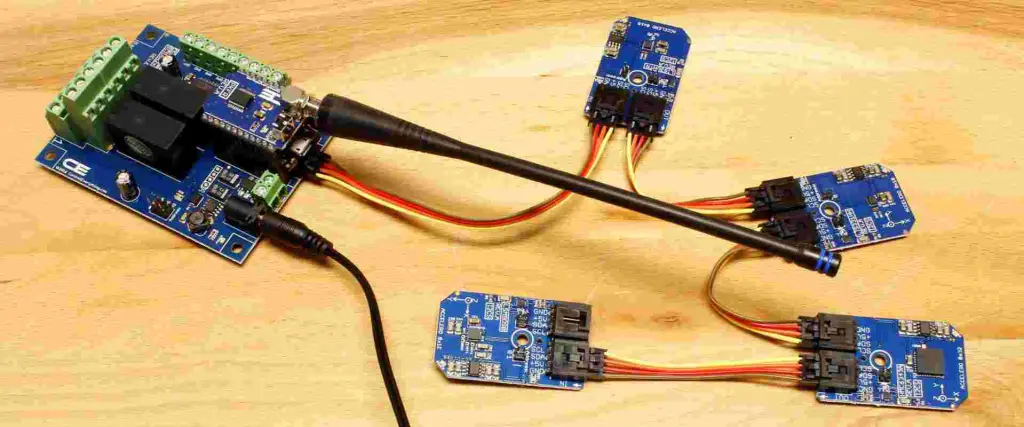
Motion sensors are essential components for building automation, security systems, and a wide variety of electronic projects. They can detect occupancy, trigger lighting control, sense intruders, and much more. With a vast range of motion sensing technologies now readily available, how do you choose the right sensor for your needs as a beginner?
This article will cover the fundamentals of how the most common motion sensor types operate, their capabilities and limitations, key specifications to understand, and examples of real-world applications. With these foundations, you will be prepared to successfully incorporate these versatile detectors into your own projects. Let’s get started!
Motion Sensing Basics
Motion sensors detect kinetic energy emitted by moving objects within their detection zone. This is accomplished by transmitting energy waves and monitoring changes in the received reflection pattern when movement occurs.
Active vs Passive Sensors
Motion sensors fall into two main categories:
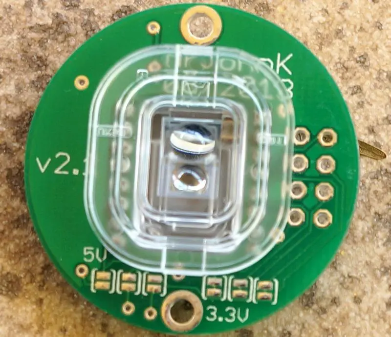
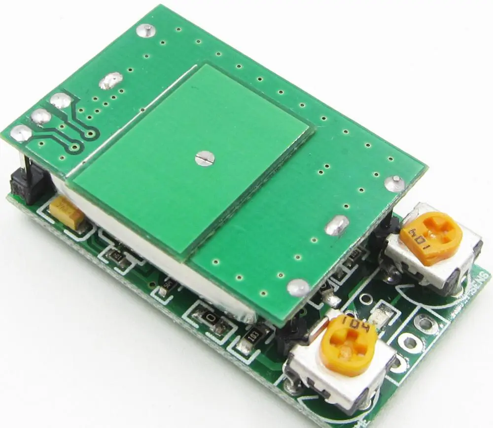
Active Sensors – Emit their own energy waves and detect changes in the reflection signature. Examples are ultrasonic and microwave sensors.
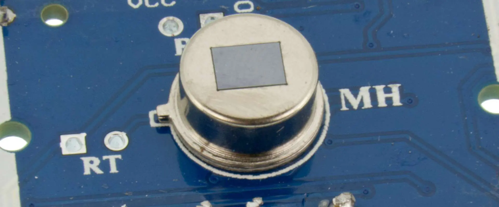
Passive Sensors – Rely on detecting infrared energy emitted by objects. Passive infrared (PIR) sensors are the most common type.
Active sensors provide their own illumination source, while passive sensors leverage infrared given off by occupants and objects at room temperature.
Detection Methods
Motion is sensed by monitoring for variation in the received energy pattern:
Doppler Shift – Used by microwave and ultrasonic sensors to detect minute frequency changes caused by motion.
Infrared Change – PIR sensors detect fluctuations in received IR as warm bodies move through a zone.
Range Measurement – Compares successive distance readings to sense position changes.
Matching the detection capabilities, range, outputs, and resource constraints of the motion sensor to the application ensures optimal sensing performance.
Installation Guidelines
Proper installation and positioning helps achieve reliable motion detection:
Mount at recommended height with unobstructed view of monitored region
Tilt angle should point sensor towards central area of interest
Avoid sources of heat, vibration, light interference in field of view
Careful attention to the manufacturer’s installation guidelines prevents many sensor issues. Testing zones of interest during setup confirms configuration.
Comparing to Datasheet – Review specifications and recommended circuits.
Simple adjustments to position, sensitivity, and wiring connections can resolve many detection problems.
Conclusion
Motion sensors provide a critical sensing element for adding automation, control, and analytics based on movement and occupancy detection. Passive infrared, ultrasonic, and microwave detectors each offer unique capabilities to match diverse applications. With an understanding of the available sensing technologies, typical specifications, interface needs, and installation considerations covered here, you will be prepared to effectively incorporate motion sensing into your next project. Just remember to thoroughly plan the implementation details and test detection zones during development. With motion sensors, a little extra planning goes a long way toward a successful project!
Frequently Asked Questions
Q: Which motion sensors work well outdoors?
A: Microwave and passive IR sensors are good choices for outdoor use since they are less affected by environmental conditions. Ultrasonic sensors perform poorly outdoors.
Q: How do you determine the optimal motion sensor location?
A: Review range diagrams to position the sensor centrally within the zone of interest. Mount at the recommended height with an unobstructed field of view of monitored areas.
Q: Can one motion detector cover an entire house or business?
A: For whole building coverage, plan on installing multiple strategically positioned sensors. Use range diagrams to avoid gaps in detection zones.
Q: What are common sources of false alarms with motion sensors?
A: Reflective surfaces, heat sources, and vibration can create false motion detection events. Proper installation and shielding is important.
Q: How fast do passive infrared sensors respond to motion?
A: Response time depends on the sensor, but is typically under 100ms. Faster ultrasonic and microwave detectors respond in just a few tens of milliseconds.
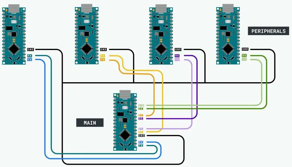
The universal asynchronous receiver/transmitter (UART) serial protocol is one of the most basic and commonly used communication interfaces found on microcontrollers. All Arduino boards feature one or more hardware UARTs that can communicate with peripheral devices, sensors, gateways, and other MCUs using just 2 wires – RX and TX.
This article provides a comprehensive guide to utilizing the Arduino’s built-in UART hardware to add serial communication capabilities to projects. We will cover UART theory, Arduino integration, connections, configurations, data transmission, and use cases through example sketches. After finishing, you will have the essential knowledge to implement robust wired serial links in your own Arduino-based designs.
UART Communication Basics
Before diving into Arduino UART programming, let’s briefly review how asynchronous serial transmission works.
Asynchronous Protocol
UART stands for universal asynchronous receiver/transmitter. The key word here is asynchronous – it does not use a clock signal to synchronize both ends of the link like SPI or I2C. The transmitting UART simply sends serial data without external timing reference.
The receiving UART determines the baud rate and timing from start/stop bits embedded in the serial byte stream. This allows the two UARTs to operate independently, only requiring common baud rate and data format agreement.
UART Hardware Interface
Just two wires are needed for basic UART communication:
TX (Transmit) – Carries serial data from the transmitting UART’s output to the receiver’s input.
RX (Receive) – Carries data in the opposite direction, from receiver back to transmitter. Provides a return communication path.
With only TX and RX crossed between the two UARTs, 2-way asynchronous serial communication can occur.
Data Frame Format
UART data is sent in configurable frames that contain:
Start Bit – Goes low at the start of transmission to signal a new byte.
Data Bits – The data byte being transmitted, typically 5-8 bits.
Parity Bit – Optional extra bit for basic error checking.
Stop Bit(s) – Goes high at end to signal the end of a byte. 1, 1.5 or 2 bits.
This frame timing allows the receiver to reconstitute the asynchronous data back into bytes using just the TX line as a reference.
The Arduino sends a formatted multi-byte string every 0.5 seconds containing the current sensor measurement. A connected device can log and parse this data.
Bidirectional Communication
For 2-way data flows, we can combine transmit and receive handlers:
Now the Arduino can both receive control commands to manipulate I/O pins and send back acknowledgement messages over the serial link.
Real-World Examples
Some common real-world applications of Arduino UART communication include:
Sending debug or status messages to a PC terminal
Interfacing with peripherals like GPS, bar code scanners
Communicating with other microcontrollers
Connecting to single board computers like Raspberry Pi
Transferring sensor data to logging and analytics systems
Remote control or reconfiguration
Almost any device with a UART interface can share serial data flows with an Arduino for an extremely flexible wired data link.
Troubleshooting Issues
If communication issues arise, here are some things to check:
Mismatched Baud Rate – Both devices must use the same baud rate. Recheck with oscilloscope.
Incorrect Wiring – Verify TX->RX and RX->TX lines are crossed properly.
Unsuitable Environment – Electrical noise or RF interference can corrupt UART signals. Check scope waveforms for noise sources.
Voltage Mismatch – Use a logic level shifter if voltage levels are incompatible.
Buffer Overflow – Slow processing of received data can overflow internal buffers and lose bytes. Increase buffer sizes.
Transmission Errors – Add checksums or CRC to validate error-free data receipt.
Distance Too Great – Long runs require regulated drivers, shielded cables, low baud rates.
Meticulous UART wiring, data validation, and baud rate checking typically resolves most serial interface issues.
Conclusion
The humble UART serial protocol remains a staple communication interface for embedded systems and microcontrollers like Arduino. With just a TX and RX connection, robust asynchronous serial links are possible over short and long distances. Carefully structuring your Arduino code to properly initialize, transmit, and receive data will enable UART’s simple 2-wire interface to solve many connectivity needs. The extensive hardware and software support makes integrating UART serial communication into your next Arduino project smooth and painless.
Frequently Asked Questions
Q: Can multiple devices be connected to an Arduino UART?
A: Yes, using RS-485 converters multiple receivers and transmitters can share an Arduino UART in a multi-drop network. The Arduino transmits to all devices, while each device takes turns transmitting in response.
Q: How fast can UART communication data rates reach?
A: Standard Arduino UARTs max out around 115200 bits/second. Faster transmission up to 1 Mbps is possible using HardwareSerial libraries and higher-speed MCU clock rates.
Q: Why is serial data garbled on the receiving end?
A: Electrical noise, loose wires, unmatched baud rates or incorrect UART settings like parity can corrupt data. Oscilloscope checks can identify the issue source.
Q: What is the maximum transmission distance of UART?
A: Using Cat 5e cable, UART can reach approx. 1000 ft at 115200 baud or 2500 ft at 9600 baud reliably. Beyond this, signal issues arise. RS-485 conversion extends distances further.
Q: How can two Arduinos communicate if they both only have one UART?
A: A software serial library like SoftwareSerial can allow using GPIO pins to create a second virtual UART for one of the Arduinos.
The Simple Dynamics of UART Arduino
UART is one of the most common and pretty basic hardware communication peripherals that electricians and makers implement in microcontrollers. Similarly, Arduinos contain UART peripherals too. Have you ever used a UART Arduino before? Are you planning on using one or your project? Would you like to know all about this incredible device? Well, in this article, we shall dig deep into UART Arduino and discuss issues such as:
What is a UART Arduino?
How does a UART Arduino work?
How does communication in UART Arduino occur?
Some Arduino UART examples and so on.
After reading this article, you will have all you require on UART Arduino and more. Hence follow along as we explore this great topic!
If you love tech, then you most probably have heard of the term Arduino, maybe from a lecturer, on the internet, or from a friend. Well, Arduino refers to an open-source electronic platform basing on hardware and software that is easy to use. Arduino boards can read inputs (for example, when you press a button or when light flashes on a sensor) and then turn the input into output (for example, activating an LED after pressing the button or turning on a motor after detecting light). You can easily tell your Arduino board what action to take by inputting a set of instructions into the board’s microcontroller. To input this instruction, you implement Arduino programming language, basing on wiring, and Arduino software for processing.
Arduino, over the years, has been the brain of a lot of projects; we are talking about thousands and thousands of projects. The device has been in use for simple tasks and complex scientific projects, with its efficiency only growing stronger by the day. What’s more, Arduino’s open-source platform has brought together a community of:
Professionals
Programmers
Artists
Hobbyist
Students
The Arduino community enables access to great Arduino knowledge to both experts and beginners. Since this community keeps on growing and each person can contribute, the knowledge base keeps expanding too!
The development of Arduino happened at the Ivrea Interaction Design Institute. Many anticipated an easy tool to implement for faster prototyping. The aim for the device was to help students who had no programming and electronic background. However, as soon as these boards hit the wider community, they grew like wildfire. The board started to change to adapt to the newly found challenges. The boards evolved from simple eight-bit boards to products for wearable, IoT applications, embedded environments, and 3D printing.
These boards are pretty simple to use, and they are also easily accessible to users. The Arduino software is also super easy to use for the novice, yet it is also flexible enough for implementation by advanced users. Arduino also dramatically simplifies the tedious processing of working with microcontrollers. Due to these reasons, Arduino has been implemented in many different applications and projects.
Arduino also has some added advantages that it offers to interested amateurs, students, and teachers over the system. They include:
Inexpensive – compared to other microcontrollers platforms, Arduino boards are relatively inexpensive. Pre-assembled Arduino boards cost less than fifty dollars, while those not assembled cost even less than this, pretty cheap.
Cross-platform – Arduino software can run on Linux, Macintosh OSX, and Windows operating systems.
Clear and straightforward programming environment – Arduino software is pretty easy to use, even for beginners.
Extensible, open-source software – Arduino software is open source which means that experienced programmers can expand the software’s capabilities. You can expand the software using C++ libraries.
Now that we know what Arduino is, let us look at UART Arduino and see the difference.
What is a UART Arduino?
UART (Universal Asynchronous Reception and Transmission) is a pretty simple protocol for serial communication that lets hosts communicate with different serial devices. UART supports serial, asynchronous, and bidirectional data transmission. It uses three lines to communicate efficiently, namely:
TX (Pin 1) – used for transmission
RX (Pin 0) –used to receive
GND – common ground
It is possible to connect the two between two separate devices, for example, USB on an Arduino and computer. UART is available on every type of Arduino board which in turn helps the Arduino in terms of communication with a pc because of its onboard USB to Serial converter.
If you write an Arduino program using Linux, Windows, or Mac OS, all you have to do to use it with your Arduino is to connect the two (your Arduino and your computer) using their USB ports.
An Arduino can have one or multiple UART pins; this depends upon the type of board in use. In this article, the project that we shall go through mainly implements an Arduino Uno; this Arduino board has one UART interface, which is present on TXO (pin 1) and RXO(pin 0). The TX0 and RX0 communicate as indicated earlier (as TX and RX). The two work together to ensure that communication between two UARTs is successful.
How many UART ports on Arduino uno come pre-installed?
Arduino uno has only one hardware UART port, this port is permanently engaged with the IDE and serial monitor. However, you can still create another port via software instructions. Using this port you can connect a second UART port driven device like a HC12 Radio module, a Bluetooth module et cetera.
However, there is a downside to this software port. It requires a great amount of help from the Arduino controller to efficiently send and receive data, this makes the port slow and less efficient compared to the hardware port.
Logic levels of UART
Logic levels of UART might differ between different manufacturers. Take, for example, Arduino Unos have a 5-V logic level, but the logic level of the computer’s RS232 port stands at +/-12 V. Therefore if you connect an Arduino Uno directly into an RS232 port, you might end up damaging the Arduino. If two UART devices do not have equal logic levels, you should use a logic level converter circuit to connect the two.
Advantages of using UART Arduino
UART Arduino are pretty simple to operate. They are also well documented on the internet as people worldwide utilize the Arduino platform. Hence, you can find a lot of tutorials online on Arduino to help you grow your knowledge of the device and its uses.
UART Arduino does not require a clock
Disadvantages of using UART Arduino
Lower speed when compared to SPI and 12C
Baud rates for every UART must be within 10 percent of each other; this prevents data loss.
UART Arduino cannot utilize multiple masters like slaves and Arduino
Arduino UART uses serial transmission to send and receive data, but what is serial transmission. Well, serial transmission is a method of transmitting data that transmits data one bit at a time. Hence UART Arduino sends information one bit at a time.
UART Communication Arduino
When computers transmit information to an Arduino, this occurs via USB (Universal Serial Bus). The USB signal is then converted into serial form, and then undergoes transmission to the UART. On receiving the data, the system will placed it inside a buffer (memory storage utilized to hold information temporarily). At this point, UART Arduino utilizes the three communication lines for efficient serial communication.
Just as the name suggests, the TX line (Transmission line) is good to efficiently send information to the recipient’s device. Hence, the sending device’s TX line should have a direct connection to the receiving device’s RX line.
In UART Arduino serial communication, these two lines send and receive information simultaneously; this means that UART Arduino can perform full-duplex communication.
UART transmits information asynchronously; this means that an external clock line does not drive the bits. But if there is no clock signal utilized to synchronize the output of bits that are being transmitted from the transmitting UART to the UART receiving the bits, how does the UART Arduino work then?
UART Bits
Instead of utilizing a clock, UART uses a start and a stop bit combined with the data packet undergoing transfer process. Here is how it works:
The start bit – Start bits show where data words begin. It is essential to synchronize the transmitter UART and the receiver UART.
The stop bit – Stop bits show when the last bit was sent. A stop bit can be one bit or multiple bits.
Data packet – They are usually nine to five bits in length. A data packet contains the information under transfer process. The information is in binary data bits form. The data packet is usually sandwiched between the start and the stop bits.
A parity bit – We mostly use it for error detection. It does the process via a single bit extra bit that one adds to the data under transmission. The parity bit tells the receiving UART whether the number of 1’s in the data under transmission is odd or even. The receiving UART can then assess whether or not the data is correct.
Baud Rate
Once a receiving UART Arduino device detects the start bit, it reads the incoming bits. However, for the reading process to be successful, the receiving UART device has to read the bits using a specific frequency, one that had been agreed upon initially by both devices. The agreed-upon reading frequency is known as baud rate. In simpler terms, the baud rate is the measure of data transfer speed.
The most commonly used baud rates when utilizing Arduino are:
9600
14400
19200
And ultimately 115200
Now that we know how a UART Arduino works, let us look at the programming side that makes this device the brains of a project. The examples provided below are some of the most essential programs involved in UART Arduino programming:
The serial.begin command is useful in starting off serial communication. Its program looks like this:
Void setup(){
//To start off serial communication for an Uno R3
Serial.begin(14400);
//To start serial communication for arduino Mega at port 3 you write
//Serial3.begin(14400);
}
Using this command, you bound the UART only to accept one parameter; this is the baud rate. In this program, we have set the baud rate to be 14400.
The Uno board Arduino board has only one port for serial communication. Hence there is no need to specify the port number. However, other boards such as the Arduino mega board have more than one port. You, therefore, have to select the exact port that you wish to start serial communication.
Once you call upon the serial.begin, incoming bytes are then listened for, and once received, they are automatically stored inside a buffer.
Buffer overflow – when the process of receiving bytes is faster than the process of reading the, we call such a situation “buffer overflow.”
Serial.available
The serial.available command is placed inside an if statement to check if any information has been received. Once it identifies that data has been obtained, it returns the number of bytes that are available for reading. Suppose there are no bytes available for reading, the serial.available command returns false or 0.
The data undergoing checks is the data that has already arrived and is being stored inside a serial receive buffer.
If the buffer has information to read, the next step should ultimately be to read the available data. You can use the serial.read command for this job; this command reads bytes from the buffer.
The serial.read command returns the first incoming byte available. If there is no data in the buffer, this command returns -1.
Serial.readByte
The serial.readByte is applicable for reading multiple bytes. You, however, have to set the number of bytes to read, for example:
Serial.readbyte(buffer, length);
The serial byte command returns the exact number of characters available in a buffer. A zero means that no data (valid) is available.
The function stops once it has read the specified amount of bytes. It would help if you implemented serial.setTimeout to avoid unnecessary stalling if the program starts to wait for data that might never arrive.
Serial.readBytesUntil
What if you do not know how many bytes of data will be received? If such a case occurs, you utilize the serial.readByteUntil command, this command has an added argument known as “character.” The serial.readByteUntil reads the available data and only stops once it has read all the available data, when it times out, or when the UART receives a special character.
Its program look like this:
Serial.readByteUntil(character, buffer, length);
How to Print using UART Arduino
Serial.print
Besides just receiving data, an Arduino can send data to another device. We use the serial.print command to print information on a serial monitor as ASCII text that humans can read. Its program looks like this:
Void setup(){
Serial.begin(14400);
Serial3.begin(14400); // for Arduino mega boards
}
Void loop(){
Serial.print(“hello world!);
Serial.print(“20”)
Serial.print(“3.959586589”);
Serial.print(270);
Serial.print(2.432);
}
Serial.println
The serial.println automatically adds a new line onto your program and returns at the text’s end.
Program example:
To achieve this feat, all you have to do is switch the serial.print used in the previous program and replace it with serial.println, for example, instead of typing in serial.print(“hello world!”); you type in serial.println(“Hello world!”);
Serial.write
If you wish to write serial numbers instead of ASCII characters you should implement the serial.write command. Here is an example of this program:
Serial.write(0*48);
Serial.write(0*45);
Serial.write(0*4C);
Serial.write(0*4C);
Serial.write(0*4F);
When you run this program it spells out “hello.”
Now that we have gone through how an Arduino works let us now look at the ft232r USB UART.
The FT232R
To get the concept of the ft232r USB UART drivers, you have first to understand the ft232r.
We can define the ft232r as a USB to serial interface for UART that implements an output through a clock generator. In addition to this, the ft232r uses synchronous and asynchronous bit modes taking the bang interface.
Now that we have that out of the way, we can now look at the ft232r UART driver.
If you are utilizing a windows operating system, you must have FT232R USB UART DRIVER to develop cool ft232r UART Arduino codes with your PC. So what exactly does the DRIVER do? Well, this software efficiently converts the language in use by the UART device into a language that your PC can understand. Your computer can hence decode any terms used in your Arduino program. You can also utilize the driver as a support element to any new functions that arise and all the USB protocols.
FT232R USB UART DRIVERS designed for windows devices are freely available. They are, however, pretty tricky to install, but no worries as we will take you through the installation process.
Different methods can be implemented in downloading the latest version of FT232R USB UART DRIVER suitable for your computer.
The first method: Update the FT232R USB UART DRIVER Version you have
If your FT232R USB UART DRIVER is old and not functioning correctly, this can be fixed via a simple software update to the newest version. We use FT232R USB UART to asynchronously carry out communication with other devices. However, achieving this feat requires a driver; this driver should help you update your FT232R USB UART DRIVER to the latest version. It prompts you, and all you need to do is monitor its instructions, and you are good. If this trick does not work, you might need to take manual steps in the installation of the driver.
The second method: Manual installation
For FT232R USB UART DRIVER, you will realize that the specific version good for windows is freely distributed but without an auto-installer. You hence have to manually install it into your device. Follow the following steps to install the drivers into your device.
Download the FT232R USB UART DRIVER from the internet. Ensure that you download this driver from a safe and secure provider.
After you have downloaded the drivers, head on to your control panel and start device manager. Right-click on exclamation mark you see (yellow in color), then select update driver software.
Extract the downloaded zip folder to get your FT232R USB UART DRIVER, and windows OS will then start the installation process. Once the installation process is done, you will have the latest FT232R USB UART DRIVER installed and you can start developing great Arduino projects.
The third method: manual installation of up-to-date latest driver from scratch
FT232R USB UART DRIVER installation from scratch can be pretty tedious and not to mention super tricky. Here are the steps to follow to achieve this feat:
Download the FT232R USB UART DRIVER
After downloading the driver, install into your device. To do so, follow the instructions provided as per installation wizard up to the very end.
Once you have completed the installation procedure, run the software and then complete the update.
Once you have extracted all the files, you will have to run the installer to enable you install UART DRIVER (FT232R USB).
On completing these steps, you must restart your computer to ensure that the FT232R USB UART DRIVER has been installed.
In summary form:
After you have downloaded the FT232R USB UART DRIVER, the next step is the installation process. You then install your serial port drive followed by the installation of the USB serial port drivers. You can run the software for the serial port. Lastly, restart the PC, this helps to confirm whether or not the driver has been installed.
Once you have downloaded the latest FT232R USB UART DRIVER, uninstall the outdated version first before installation. You can then uninstall the earlier USB serial converter driver when you are done. Once you have taken care of this, you may install and utilize your ft232r USB UART without any issues.
It is crucial to remember that you cannot install FT232R USB UART DRIVER once you happen to delete it.
Official FTDI providers
FT232R USB UART DRIVER can be freely downloaded by visiting FTDI website. All you should do is search using the precise keywords, and the internet will do the rest for you.
Arduino UART example
Arduino Uno Rev3
The Arduino Uno Rev3 is an incredible UART microcontroller board that is based on the ATmega328; this Arduino has the following specs:
The Arduino Uno Rev3 is an incredible UART Arduino that you can utilize to test out the strength of UART technology.
The seeeduino v4.2
Another Arduino UART example is the seeeduino v4.2. For starters, this board is compatible with Arduino based on ATmga328P MCU. The seeeduino is pretty easy to use, and it is much more stable compared to other Arduino devices. You can also try out this board to take things up a notch.
Conclusion
Tech is evolving pretty fast; new inventions are coming in every day, all meant to improve our lives. Most of these inventions utilize Arduino boards as the brains of the project; this makes choosing the correct Arduino board pretty crucial. In this article, we have gone through all you need to know about UART Arduino, from its meaning down to Arduino UART examples. All this information will help you craft out a fantastic tech project. We hope that we have answered all the questions you might have had on the topic.