Take Control of Your Systems with the Control Box Assembly

Set-top box PCB Board

Do you need to exert control over something in your house or place of business but need help determining where to begin? Be at ease! The assembly of the control box will save the day! The control box assembly is crucial to many different devices and systems, from industrial and commercial to household ones. It is a group of pieces and elements that support the observation, management, and control of various processes. Several testing techniques are available, including point-to-point, resistance, voltage, wire position, and functional testing, to ensure the control box assembly functions appropriately. In this article, we will detail the control box assembly’s definition, parts, and testing procedures.

 Control Box Assembly: Definition

A control box assembly is a collection of parts and components that provide a way to control systems or devices. It is helpful in industrial or commercial settings but applies to residential applications. Additionally, control boxes are critical to many systems and help regulate, monitor, and control various processes.

Components of a Control Box Assembly

pcb box build assembly

A control box assembly typically has the following components:

1. Control panel:

The control panel is the main interface of the control box assembly, through which the operator may observe and manage the various operations of the system. Control panel includes indicator lights, a display screen, and a variety of input devices, including buttons, knobs, switches, and sliders. The control panel shows current information about the system’s condition, such as temperature, pressure, and power usage. It sends signals through an indicator light to the operator in case of problems such as overload or malfunction. Additionally, the operator can modify several factors using input devices, such as temperature or speed, improving the system’s efficiency.

2. Fuses:

Fuses protect the system from overloads. During the manufacturing process, designers position the fuses between the power supply and the system’s electrical components such that they will blow if the current is too high. This way, the fuse prevents the system from becoming damaged due to an overload.

3. circuit breakers

Circuit breakers are safety devices that protect the system from overcurrents and short circuits. Like fuses, they trip or open the course when the current exceeds a specific limit. However, unlike fuses, you can reset circuit breakers after tripping them, making them more convenient for many applications. Circuit breakers are commonly helpful in residential and commercial electrical systems, as well as in industrial machinery and automation systems.

4. Knobs

Knobs are input devices that allow the operator to adjust various parameters, such as temperature, speed, or volume. They consist of a rotating shaft and a pointer or indicator that shows the current setting. Knobs are helpful in household appliances, such as ovens and stovetops, and audio and video equipment.

5. Sliders

Sliders are input devices that allow the operator to adjust parameters, such as brightness or volume, by moving a lever or slider along a track. They consist of a graduated scale or indicator that shows the current setting. Furthermore, sliders commonly help in audio and video equipment, as well as in lighting control systems.

6. Switches

Switches allow the operator to turn the system on or off or to switch between different modes or functions. They have a lever or button that users can toggle or push to activate or deactivate a circuit.

Testing Methods of the Control Box Assembly

FULL PCB MANUFACTURING Quote

The following methods will enable you to verify the functionality of your control box assembly for excellent results:

1. Point-to-Point Testing:

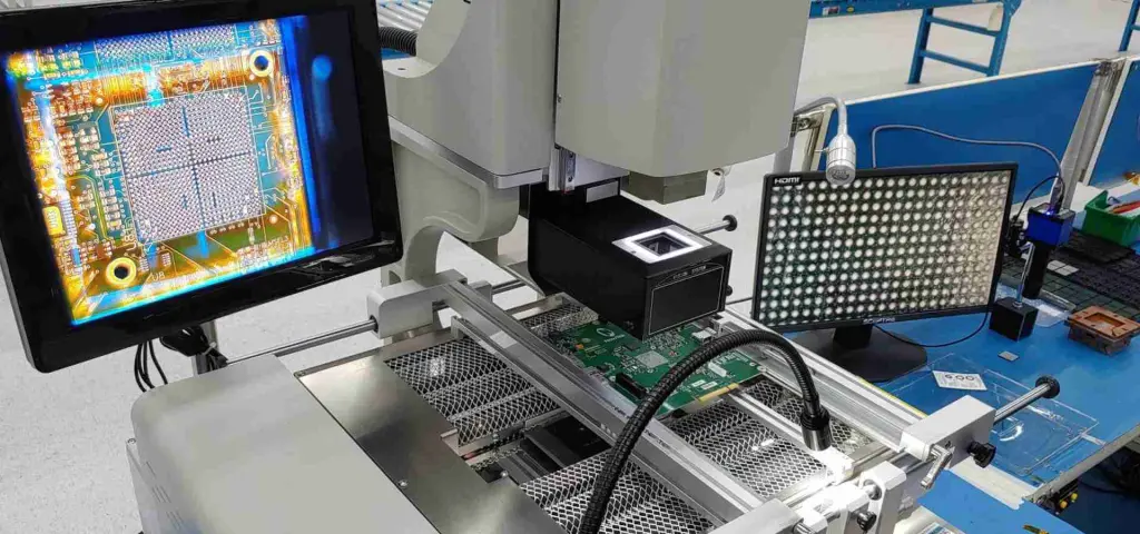
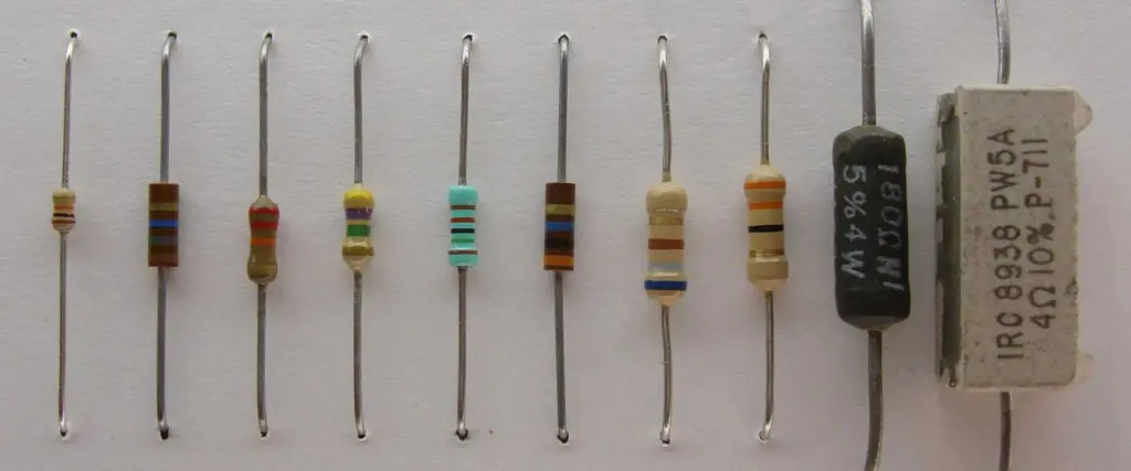
In point-to-point testing, the engineer examines each component of a control box assembly separately. This strategy is quite helpful when there is heavy wiring of components. The engineer must, therefore, visually inspect each element and the wiring that connects it for any indications of damage or misconnected wires. In addition, a multimeter can help check the components’ connections by measuring their resistance. Before powering on the control box assembly, please do this to assist you in identifying any potential problems.

2. Resistance Testing

Resistance testing on a control box assembly assures proper operation. You start by connecting a testing device to measure the circuit resistance to the control box. By employing this method, you will quickly discover any problems or defects in the box that might prohibit it from functioning correctly.

To perform the resistance test, please link the control box to a testing setup that consists of an Ohm meter and a test lead. Next, connect the control box to the Ohm meter once you have installed the test lead. Then, using an Ohm meter, calculate the resistance of the control box circuit.

If the resistance is less than the bare minimum allowable value, the box has a problem. Many control box defects can be easy to find using the resistance test. These flaws could be corrosion, damaged connections, frayed cables, or any other fault impairing the control box’s functionality. Before utilizing the package, please correct any flaws you may have found.

3. Voltage Testing:

Voltage testing is a method for making sure the control box assembly has the appropriate voltage. Checking the voltage within the set range is essential to guarantee that the control box assembly operates correctly. Use a clamp meter or a voltage meter for this test. You will have to measure the voltage of the control box assembly using a voltage meter and compare its reading to the desired value. Please fasten the clamp meter to the cables entering and exiting the control box assembly to measure the voltage. As a result, the voltage may now be easy to measure with greater accuracy.

4. Wire Position Testing

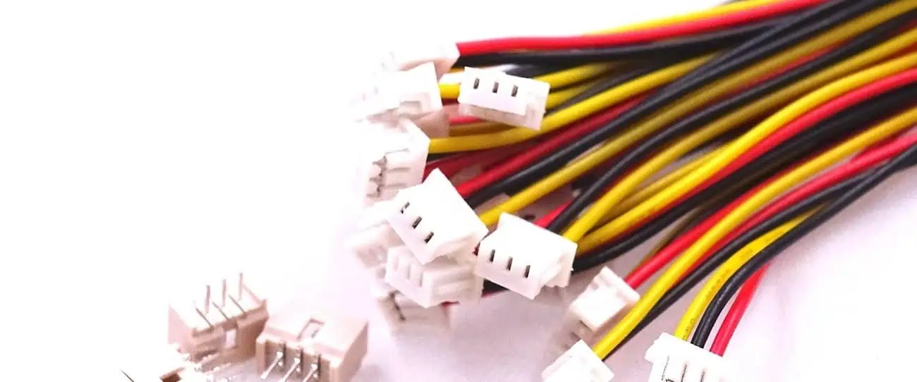
Wire position testing helps ensure that every wire connection is accurate and that you have utilized the correct terminals for each wire. This action is crucial since improper wiring connections can lead to electrical issues and potential malfunction of the control box assembly.

Visual inspection of the wiring connections and labeling is the first step of the wire position test. Next, the technician should follow each wire to its proper terminal and reattach it if he discovers any differences. After ensuring that all wiring connections are accurate, the technician should then use a multimeter to test the resistance between each terminal and its corresponding wire.

The resistance should be within the acceptable range for the specific control box assembly. If the resistance is too high or too low, the technician should replace the wire or the terminal.

5. Functional Testing

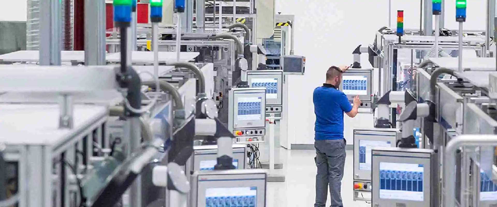
Functional testing enables verification that the control box assembly’s design satisfies all requirements and carries out all intended functions as intended. Typically, the engineer examines the input, output, and other parts of the control box assembly as part of the functional testing procedure to ensure they comply with all the specifications.

Functional testing may be manual, automated, or a combination. Automated testing usually suits large and complicated control box assemblies, while smaller and simpler ones require manual testing. While manual tests may entail personally checking each component or functionality, automated tests may entail running scripts or programs.

Typically, engineers perform functional testing for control box assemblies by contrasting the behavior and outcomes of the control box assembly with the specification documents. Many techniques, like running simulations, doing tests in a lab setting, or even personally testing the control box assembly, can help complete this process.

Conclusion

In conclusion, a control box assembly is crucial to many systems and helps regulate, monitor, and control various processes. It comprises several components: control panels, fuses, circuit breakers, knobs, sliders, and switches. Moreover, it is essential to test the control box assembly to ensure its operation and functionality. Point-to-point, resistance, voltage, and wire position testing are methods used to detect potential problems with the control box assembly. Therefore, it is essential to maintain and regularly check your control box assembly to keep your system working efficiently.

Why You Need a Mobile IC Reballing Kit for Your Reballing Process

BGA Rework Services

We all have devices we utilize on a regular basis. For instance, most people have cars they drive frequently. Some people have jobs that need specialized equipment they would constantly use. This includes construction tools or custom-made computers.

A device that is constantly being used will need maintenance, repairing or both. Otherwise, such a device will begin to malfunction or stop working at all. This same principle is applicable to mobile phones. The IC in a mobile phone can get damaged due to constant use. Therefore, there is a need for repair. Since a mobile IC is always in constant use, it will definitely need repairs or maintenance. This repair is what we refer to as reballing.

Read further to understand the principle of mobile IC reballing. You will get to know everything about mobile IC reballing kit in this article.

What is Mobile IC Reballing?

Mobile IC Reballing Kit

IC reballing is a technique that involves repairing a faulty or damaged Integrated circuit in a mobile phone. Reballing is commonly integrated in PGA and BGA chips. Also, reballing can help to other electronic components like capacitors and resistors. The mobile IC reballing is a time consuming process that requires much effort.

If an IC has gotten damaged, reballing is often recommended to save the IC from being scrapped. There are some reasons why you have to reball an IC chip. Mobile IC repair is carried out on mobile phones. The most common reasons a mobile IC reballing is important include:

  • The mobile IC is faulty and needs to be repaired
  • The solder joint between the IC chip and a PCB have become very loose
  • You need to redo or update the IC chip since the PCB is upgraded

The Integrated circuit is a crucial component on your mobile phone. It restricts the functionality of your phone when it gets damaged. However, this component can  be fixed.

Reballing involves changing the soldered balls on an integrated circuit chip. BGA circuit design is made to have a contact between the chip and the PCB. As a result of some reasons, engineers need to recreate the ball solder joints. Reballing is a process that simply involves getting rid of old solder balls. These solder balls are then replaced with new ones.

How do you Detect a Damaged IC on your Mobile Phone

FULL PCB MANUFACTURING Quote

It is quite difficult to know if your mobile IC is damaged. However, there are some unusual things you will discover on your phone if its IC is damaged. This includes:

Heat condition

Your mobile IC is damaged if a heat contrast is with closely related IC. When your mobile phone IC unnecessarily heats up when there is a supply of voltage, then your phone is damaged.

Leaked or burnt IC

If your mobile IC has  a leaked spot or gets burnt is already damaged. You can easily locate a damaged spot by looking closely on each side of the mobile IC. A burnt IC can never work on your phone.

Open circuit

This is another reason you might have a damaged IC on your phone. Open circuit refers to any incomplete electrical circuit. Your phone IC is damaged if there is an open circuit. Open circuit usually causes a breach in the mobile IC.  If you notice an opened mobile phone IC at a point, you have a damaged IC.

Causes of Mobile IC Problems

There are various causes of mobile IC problems.

Power surge

Your IC can become irreparable if there is a high power. For example, an overrated charger can cause a power surge. An overrated charger has a greater amount of current compared to what your phone can take. Furthermore, a power surge may be as a result of your phone being struck by lightning and thunder while it is being charged. Therefore, a power surge that occurred earlier can be the reason why your mobile IC is damaged.

Moisture

This is another common cause of mobile IC damage. When your mobile phone contains moisture, this may cause a damage to your IC. Moisture occurs when water splashes on your mobile phone or when it falls into water. This could cause damage to your IC and other sensitive components of your mobile phone.

Manufacturer defects

IC problem might not happen due to your carelessness, it could be the manufacturerโ€™s fault. If your mobile phone is faulty right from the time you purchased it, there are high chances it has some IC problems.

Mobile IC Reballing Kit

bga-reballing-station

The reballing process isnโ€™t as easy as it seems. When reballing a mobile IC, there are various kinds of supplies and tools needed. The saddest part of this process is that all required supplies and tools are expensive. This is the major reason people donโ€™t carry out reballing at home.

Therefore, you will need a mobile IC reballing kit and a mobile IC rework machine. The mobile IC reballing kit is available online. These tools are what you require when carrying out a mobile IC reballing. The mobile IC reballing kit features all the necessary tools you need to reball a mobile phone IC.

The reballing process requires the use of appropriate standards, tools, and procedures. Also, the mobile IC reballing kit makes reballing much easier and faster. Furthermore, this kit offers almost everything you need for the reballing process. The price of a mobile IC reballing kit varies based on manufacturers.

Why is Mobile IC Reballing Needed?

Integrated circuits offer more durability compared to traditional arrays. However, the connection on the IC chip may become very loose as a result of exposure to harsh conditions or constituent use. A mobile IC may become damaged due to consistent use. Therefore, it is necessary to reball mobile IC to prevent malfunctioning.

The technology market needs upgradation of the mobile IC so as to keep up with the transformation. This is possible to achieve through IC reballing. Therefore, this will enhance the life span of the device. Furthermore, reballing is crucial when the motherboard needs to go through graphic chip up-gradation.

PCBs experience some heating cycles which can make a chip become unreliable. Also, heating can result in solder bridging and as such reballing comes into play. Faulty mobile IC chips needs reballing to ensure they offer optimal performance.

Some of the reasons you need to reball a mobile IC is when there are issues with the solder balls or soldering, a need to update the IC or repair a faulty IC. One easy way to get the mobile IC repaired is by replacing the damaged IC. Replacement is another option you can consider asides reballing.

You will need to desolder and solder the damaged IC using another IC. It is crucial you reball your damaged IC. However, replacement is a good option to put into consideration.

Tools Needed for Reballing

Soldering paste

Solder paste is widely integrated in the manufacturing of printed circuit boards. This paste connects electronic components to pads on the PCB. Therefore, it helps to put the electronic components in place or solder balls on the mounted area.

Solder balls

Solder balls are very crucial when reballing. These are small balls of solder scattered all over the surface of the PCB board. These balls offer contact between the printed circuit board and the chip package. Also they provide contact between stacked packages available in multichip modules.

Soldering iron

This hand instrument helps in soldering parts. It melts the solder metal and allows it to flow to the joints between the electronic components and the PCB. Soldering iron is a heated metal tip and  an insulated handle.

Desoldering wire

Desoldering wire soaks all the metal solder in a solder joint to remove all the solder present in the joint. It is also referred to as desoldering wick.

BGA rework machine

This machine supplies the necessary heat needed to remove or attach the BGA chips.

BGA chip stencil

This is a piece of metal sheet that features lots of holes for solder balls. The BGA chip stencil is made of steel. Therefore, you can heat it by using BGA machine or hot air gun to make the process of soldering easy.

BGA chip case

This is a holding stand designed for holding Chips for the purpose of reballing.

Conclusion

Since a mobile IC is always in constant use, it will definitely need repairs or maintenance. This repair is what we refer to as reballing. If an IC has gotten damaged, reballing is often recommended to save the IC from being scrapped. There are reasons why you might require reballing an IC chip.

Reballing a mobile IC can be very difficult because of the tiny fragments present in the IC. Therefore, it is advisable to hire a technician to help you with the reballing process. Reballing a damaged mobile IC isnโ€™t something you can do all by yourself. Therefore, you can hire a professional technician to help you do so.

Precision BGA Assembly Services for High-Density PCB Applications

Introduction to BGA Assembly

In the ever-evolving world of electronics, Ball Grid Array (BGA) assembly has emerged as a game-changing technology for high-density PCB applications. But what exactly is BGA assembly, and why is it so crucial in modern electronics manufacturing?

BGA assembly is an advanced surface-mount packaging technique that involves attaching integrated circuits (ICs) or other components to a printed circuit board (PCB) using an array of solder balls. These tiny spheres serve as both electrical connections and mechanical supports, enabling higher component density and improved performance.

As devices continue to shrink while demanding more power and functionality, BGA assembly has become indispensable. Let’s delve deeper into this fascinating technology and explore its impact on the electronics industry.

Types of BGAs: A Comprehensive Overview

eMMC BGA

Our state-of-the-art facility is equipped to handle a wide variety of BGA types, each suited for specific applications. Here’s a rundown of the most common BGA types we assemble:

1. Fine Pitch BGA (FPBGA)

FPBGAs feature a ball pitch of 1.00mm or less, ideal for high pin count applications in a compact area.

2. Very Fine Pitch BGA (VFPBGA)

Taking miniaturization further, VFPBGAs have ball pitches of 0.5mm or less, perfect for ultra-compact devices.

3. Thin Chip Array Ball Grid Array (CTBGA)

With a package thickness under 1.2mm, CTBGAs are the go-to choice for slim devices like smartphones and tablets.

4. Wafer Level Chip Scale BGA (WLCSP)

WLCSPs are among the smallest BGA packages, manufactured directly on the wafer. They’re commonly used in mobile devices and wearables.

5. Fan-Out Wafer Level Packaging (FOWLP)

FOWLP extends wafer-level packaging, offering higher I/O density and improved thermal performance.

6. Plastic Ball Grid Array (PBGA)

PBGAs use a plastic substrate, offering a good balance of performance, cost, and reliability for various applications.

7. Ceramic Ball Grid Array (CBGA)

Utilizing a ceramic substrate, CBGAs excel in thermal management and electrical performance, making them ideal for aerospace and military applications.

8. Tape Ball Grid Array (TBGA)

TBGAs feature a flexible tape substrate, reducing stress on solder joints in applications prone to thermal cycling or mechanical stress.

9. Flip-Chip Ball Grid Array (FCBGA)

FCBGAs combine flip-chip and BGA technologies, offering excellent electrical performance and thermal management.

10. Enhanced Ball Grid Array (EBGA)

EBGAs incorporate enhanced thermal design features, suitable for high power dissipation applications.

11. Metal Ball Grid Array (MBGA)

MBGAs use a metal substrate for superior thermal performance, ideal for high-power applications.

12. Micro BGAs

With ball pitches of 0.4mm or less, Micro BGAs are perfect for extremely space-constrained applications like wearables and IoT devices.

Learn more about:

The Compelling Advantages of BGA Assembly

bga rework process

BGA assembly offers numerous benefits over traditional through-hole and other surface-mount technologies. Here’s why it’s become the preferred choice for high-density PCB applications:

  1. Higher component density: BGAs allow for more connections in a smaller area, enabling the creation of smaller, more compact devices.
  2. Improved electrical performance: Shorter connection lengths reduce signal delays and parasitic capacitance, resulting in better high-frequency performance.
  3. Enhanced thermal management: Many BGA designs incorporate features for improved heat dissipation.
  4. Self-alignment during reflow: The surface tension of molten solder tends to align BGA components correctly, reducing misalignment risks.
  5. Reduced mechanical stress: The array of solder balls distributes stress more evenly across the package, improving reliability.
  6. Better protection of interconnections: Solder balls are hidden beneath the package, shielding them from mechanical damage and environmental factors.
  7. Simplified PCB routing: The array layout of connections often simplifies PCB routing compared to traditional leaded packages.
  8. Improved manufacturability: BGA assembly can be highly automated, leading to increased production efficiency and consistency.
YouTube video

The BGA Assembly Process: A Step-by-Step Guide

Achieving high-quality BGA assembly requires precision and attention to detail. Let’s walk through the key stages of the process:

1. Initial Design and Layout

The PCB design must account for BGA-specific requirements, including proper pad design, trace routing, and thermal considerations.

2. PCB Preparation

Thorough cleaning and inspection ensure a contaminant-free surface for assembly.

3. Baking Procedures

BGAs and PCBs are often baked before assembly to remove moisture, preventing issues like popcorning during reflow.

4. Stencil Creation and Inspection

A high-precision stencil is created for applying solder paste to the PCB, followed by careful inspection to ensure accurate apertures.

5. BGA Placement

Advanced pick-and-place machines accurately position BGA components on the PCB.

6. Reflow Soldering

The assembled PCB undergoes a carefully controlled reflow process, where the solder paste melts and forms connections between the BGA balls and PCB pads.

7. Cleaning and Inspection

After reflow, the PCB is cleaned and undergoes thorough inspection to ensure proper solder joint formation and component alignment.

Ensuring Quality in BGA Assembly: Best Practices

bga inspection

To achieve high-quality BGA assembly, several factors must be carefully controlled:

  1. Proper solder paste selection and application
  2. Accurate component placement
  3. Optimized reflow profile
  4. Controlled atmosphere during reflow
  5. Proper cooling rate after reflow
  6. Minimization of mechanical stress during handling

Verifying Solder Joint Quality: Inspection Techniques

Checking the quality of BGA solder joints is crucial for ensuring reliable connections. Here are the most effective inspection methods:

  1. X-ray inspection:ย Allows visualization of solder joints beneath the BGA package
  2. Automated Optical Inspection (AOI):ย Used for inspecting visible aspects of the assembly
  3. In-Circuit Testing (ICT):ย Verifies electrical connections and component functionality
  4. Thermal imaging:ย Can reveal issues with thermal management or inconsistent solder joints
YouTube video

Common Defects in BGA Assembly and How to Avoid Them

Despite best efforts, defects can occur in BGA assembly. Here are some common issues and tips to prevent them:

  1. Misalignment:ย Ensure precise component placement and use self-alignment properties of BGAs.
  2. Inconsistent Standoff Height:ย Control solder paste volume and reflow profile carefully.
  3. Missing Balls:ย Inspect BGAs before placement and ensure proper handling.
  4. Non-Wetted Pads:ย Use appropriate flux and ensure proper surface preparation.
  5. Bridges:ย Optimize stencil design and solder paste application.
  6. Partial Reflow:ย Fine-tune the reflow profile for complete solder melting.
  7. Popcorning:ย Implement proper moisture management procedures.
  8. Open Circuits:ย Ensure proper pad design and solder paste application.
  9. Voiding:ย Optimize reflow profile and consider vacuum reflow for critical applications.

Conclusion: The Future of BGA Assembly in High-Density PCB Applications

As the demand for smaller, more powerful electronic devices continues to grow, BGA assembly will play an increasingly critical role in high-density PCB applications. By understanding the various types of BGAs, the intricacies of the assembly process, and the key factors that influence solder joint quality, manufacturers can leverage this technology to create innovative, reliable electronic devices.

Whether you’re designing cutting-edge mobile devices, high-performance computing systems, or reliable aerospace equipment, mastering BGA assembly is essential. With the right expertise and advanced manufacturing capabilities, the possibilities for innovation in high-density PCB applications are virtually limitless.

Are you ready to take your PCB designs to the next level with precision BGA assembly? Contact our team of experts today to learn how we can help bring your high-density PCB applications to life.

What is CPU PCB? Manufacturing and Supplying

CPU PCB

Several of the electronics people use daily contain CPUs. For instance, smartphones, PCs, and other gadgets use CPU PCBs. Computer keyboards, monitors, & printers are just a few products that use CPU PCBs and microcontrollers (which incorporate CPUs).

You’ve arrived at the appropriate location if you’re looking for information on CPU PCBs. We’ve compiled a list of insightful inquiries about CPU PCBs, and we want to provide you with solutions. Let’s get started right now without further ado.

What Is CPU PCB?

The printed circuit board or PCB supports the electrical parts that power and enable the functionality of electronics. The PCB, often constructed of copper or another material that conducts electricity, is etched to permit the movement of electrical currents. Prepreg & TEFLON, among other non-conductive materials, comprise the PCB’s basis.

A CPU PCB is a circuit board that acts as a platform for a computerized device’s central processor (CPU) and controllers. Moreover, these PCBs feature industry-standard architecture, modular PC cards, and peripheral component connection (PCI) (ISA). Different standards, such as the PCI extended for instrumentation cards (PXI) and the extended embedded technology classification, are added (ETX).

Designing A CPU PCB

FPGA vs. GPU vs. CPU

The CPU Pcb design differs significantly from conventional PCB design in several ways. When designing the CPU PCB, especially when using multilayer boards, other processes must be followed. We will describe the procedure for creating a CPU PCB using multilayer boards in the following section.

Choose The Component Mounting Technology

Surface and through-hole mounting are the two main techniques for attaching components to a PCB. Components are mounted to the Board using surface mounting via an automated process. To fit the components, through-hole technology, on the other hand, involves drilling holes inside the PCB foundation. The decision of which approach to take for a particular design is based on some variables and design considerations.

Determine The Microcontroller

The microcontroller, which is the main element of the CPU PCB, must be carefully chosen to satisfy the demands of the application. To guarantee the best possible performance of the CPU PCB, it is crucial to select a microcontroller with the correct performance requirements, including overclocking speed.

USB To Serial Converter

The CPU needs to communicate with the computerized system to function. To help translate the signals from the CPU to the automated process through a USB port, an additional chip is needed. On the microcontroller, the signal can be retrieved using synchronous serial peripherals like UART.

Analog To Digital Peripherals

When converting an analog signal into digital signals and enhancing overall usefulness, choosing the suitable analog-to-digital signal converter was essential. It’s crucial to thoroughly analyze and choose the converter that is best suited for the particular application.

CPU PCB grounding techniques

Grounding PCB Techniques 

FULL PCB MANUFACTURING Quote

Grounding is vital in PCB design; therefore, following the correct grounding procedures is necessary for the best results. The following are crucial pointers to remember regarding grounding for PCB design.

1. Ensure Everything Is Attached

Scrutinize your PCB layout to make sure there are no loose components. Consider covering open spaces with copper or vias that link to the ground plate for the best performance. This strategy will lay out a clear path for effective signal transmission to the ground.

2. Keep Ground Layer Whole

On a specialized ground layer, which is frequently found in four-layer boards, make sure there are no route traces. Avoid breaking up the ground layer by adding route traces to prevent producing a ground current loop. Instead, make sure the ground layer is intact.

3. Have a Common Ground Point

It is advised to have a central position where all grounds converge to provide a good grounding in a PCB. A specific layer of the board or the product’s metal chassis can be used for this purpose. Because the conductors radiate from this entry point in the shape of a star, it is often referred to as a star ground. To preserve signal integrity in mixed-signal systems, separate analog and digital power sources may be necessary, as well as separate analog or digital grounds that join at the star point.

4. Minimize the Use of Series Vias

Reduce the number of vias in your ground routes and ensure that component grounds are connected directly to a ground plane to avoid impedance and voltage differentials. Impedance can be increased by adding extra vias to the board, which is crucial to consider for fast transient currents that may result in voltage differentials all along the impedance path.

5. Design Grounding Before Routing

Before beginning any routing process, it is critical to design a ground structure. It’s critical to ensure the ground is adequately planned because it is the foundation for routing. While problems with one signal not functioning as planned may not significantly impact, poor grounding might represent a serious risk to the entire system.

6. How Currents Are Flowing

Understanding the current flow on a circuit board can help ensure proper grounding. It is crucial to consider the signal’s final destination and matching return path. Since the outgoing and returning signal pathways contain the same currents, they can affect the power stability and occurrence of ground bounce.

7. Dynamic Variance B/W Grounds

Consider the possibility of dynamic differences while connecting the ground between several systems’ boards. When working with applications that make use of long-distance wires, this becomes even more crucial. Optical isolators, reduced voltage differential signals, or common-mode chokes can all be utilized to keep the variations in check.

8. Mixed-Signal Considerations

When working with both analog and digital on a board, careful planning is required. It’s crucial to separate the digital parts from the analog sections, including the analog-to-digital converter topologies (ADCs) or digital-to-analog converters. To achieve this, the ADC’s grounds can be connected and linked by a standard ground pin, allowing digital signals to travel to other areas of the PCB.

What is the Significance of Smartwatch IoT?

Smartwatch IoT

Sportspeople and those who wish to get in better physical shape have grown to rely on connected watches as well as activity trackers as their “indispensable” companions. These advanced devices gather a lot of information about our movements, activities, and vital signs (age, weight, sex, sleep cycle, heart rate, etc.).

Based on our activity, they could be linked to a variety of external sensors that add extra information. Smartwatches are typically connected to a platform for data storage that enables users to see, analyze, as well as share their actions. The security of these items is a major problem given the type of data they connect.

What Does a Smartwatch Mean?

A wearable computer that strongly matches a wristwatch and other timepiece devices is called a smartwatch. Several smartwatches are known to be bluetooth-capable and can tell the time. The watch transforms into a bluetooth adaptor that may bring the features of the smartphone towards the timepiece.

The interface of the watch can be used by the wearer to make and take phone calls via their mobile device, read text and email messages, obtain weather information, play music, compose text and email messages, and communicate with a digital assistant.

Some smartwatches are separate gadgets that provide a particular function. For instance, certain smartwatches gather information regarding the user’s health, such as tracking the user’s heart rate. Others give the wearer driving or walking directions using GPS information.

What Functionalities are available on Smartwatches?

Smartwatch IoT Device

Smartwatches come with a lot of functions. These include the following:

  • Healthcare informatics like level of blood oxygen, temperature and blood pressure monitoring, and heart rate
  • Calling and messaging capabilities akin to those found on the smartphone
  • For emergency calls if the wearer falls
  • Social media as well as other notifications gotten from synchronized mobile apps
  • Games, photos, music, as well as other entertainment alternatives
  • Location capabilities like maps, compass, and an altimeter
  • GPS tracking

In most cases, smartwatches connect to the user’s smartphone. The watch has many of similar functions and software programs as the phone and can sync with it. Users of Apple Watch must also own any Apple iPhone.

Smartwatch Types

There are several all-purpose smartwatches available on the marketplace which offers a range of capabilities. Some examples of this are as follows:

  • Apple’s all-purpose smartwatch is the Apple Watch
  • There are numerous companies that create and market timepieces using the Wear OS of Google.
  • Samsung’s exclusive smartwatch OS is used by Tizen watches.

Smartwatch IoT Use Cases

If you always keep your smartphone nearby when you’re out as well as about, you’ve certainly encountered a circumstance where you only glanced away briefly before realizing that you had missed a very important message or call.

You can receive notifications right away by using a connected watch or smartwatch to connect to the smartphone. You should be conscious of the smartphone even if it is only close and examine it occasionally. Instead, you wouldn’t have to be concerned about missing any of these important detail because you will be informed just by wearing one.

Get top-notch health management features

These watches come with features that make it simple for users to maintain their health. Apps that assess the heart rate as well as those which record the path you take when exercising are common examples. Health-conscious folks who regularly cycle or run find these features to be quite appealing.

Similarly, some apps allow you to track your sleep, which is seen as a wonderful feature for people who are concerned about the biological clock.

Easily assess the weather

FULL PCB MANUFACTURING Quote

There are definitely instances when you do not really feel like unlocking your smartphone only to assess the weather using an app because mornings are typically busy.

You can effortlessly check the weather with connected watches and smartwatch IoT coupled with performing your morning tasks.

Serves as mobile wallet

Every year, the number of people adopting a wearable payment device increases. You can leave the house with no credit card or cash and make purchases with your wristwatch by downloading the app for mobile payments. It makes using public transportation simple and enables you to stop by any store while out for quick run or stroll even though your wallet isn’t with you.

Playing music

You may stream as well as play music if you own a connected watch or smartwatch. You can do it with some devices even if you don’t have a smartphone. When you wish to run while listening to music but are unable to bring your smartphone along, they are useful.

Easily set an alarm on your wristwatch with your smartphone

One feature that makes people utilize these watches is the alarm feature. By linking it to a smartphone, you may quickly set up an alarm. When using a smartphone and paying attention to something, you could miss the alarm going off. Yet with these watches’ vibrating alarms, you wouldn’t have to stress about it anymore. When you’re concentrating on work or catching a nap, this popular feature is helpful.

Experience effortless time conversion when traveling overseas

While traveling abroad, changing the time on your device might be a hassle. Immediately you get there, you ought to verify the time and manually change it.

Even when you’re traveling abroad, you won’t need to worry about connected watches and smartwatch IoT because all you need to do is set the location, then the watch would automatically change to the local time.

What are the Advantages of the Smartwatch IoT?

Smart watch IoT

Below are a few key aspects of wearable IoT

Better management of health

When smart wearables first came out, the only health-related features were step counts and the heart rate monitor. A smartphone or other portable device would receive the data gathered by a smart wearable and organize your fitness regimen based on your BMI.

With the convergence of smartwatches and the internet of things, a variety of useful applications are feasible:

  • Monitoring a baby’s crib continuously to provide prompt attention to a toddler;
  • Enhancing patient-centric healthcare through data streaming in real time of vital signs.
  • Make emergency care for the elderly easier.
  • Depending on the person’s health, the smartphone app may even provide reminders to drink water.

Navigation and communication

Certain smartwatches have built-in communication features, and you can add a SIM card to connect them straight to the Web. The feature is ideal for using a GPS or SatNav while traveling. Pets could be fitted with smart wearables to help in tracking them. A smartphone is not necessary thanks to the built-in calling and texting capabilities of some smartwatches.

The smartwatch already established itself as a helpful covert tool thanks to its built-in cameras. Some smartwatches offer elderly patients emergency treatment. They can summon the help of their caregivers or some emergency services such as hospitals by simply tapping or clicking the screen. Certain smart devices can also monitor babies; they can let you know if the child is weeping or doing fine.

Device management

Also, the IoT ecosystem is accessible through the smartwatch. Your smartphone as well as a number of other gadgets are connected to it. You might receive a vibrating or sound alarm if you leave your cell phone behind and move beyond a certain range. Certain smart devices even allow you to locate a missing phone. Some devices additionally include a remote control feature, which helps in deleting or encrypting data or lock your phone permanently.

What is the Future of the Smartwatch IoT?

Smart watch PCB Board

In the past 50 years, smartwatches have seen many changes. Complex data regarding the wearer can now be tracked, stored, and transmitted by them.

Biometric data is one area on which several smartwatch manufacturers have been concentrating. Smartwatches can track fitness data such as daily steps as well as body composition. Also, they can keep an eye out for prospective medical issues. The goal of manufacturers is to increase the number of health-related technologies that can be incorporated into smartwatches.

 The increased prevalence of chronic diseases that demand ongoing monitoring is one factor contributing to the focus of healthcare. In this regard, smartwatches are beneficial. In addition, the smartwatches are helpful for recognizing COVID-19 exposure as well as contact tracking thanks to their integrated GPS, health, as well as mobility characteristics.

With better real-time access to the health data of a patient, medical professionals may offer more individualized care and spot ailments before they worsen.

Conclusion

As we learnt, A wearable computer that strongly matches a wristwatch and other timepiece devices is called a smartwatch. You can track your GPS locations, keep an eye on your fitness levels, and read text messages faster thanks to smartwatch IoT. The best part is that the majority of the gadgets that let us accomplish this are portable and hands free, so you don’t need to pull them out of your pockets.

Several of the aforementioned pieces of information could be acquired prior to wearables, but doing so sometimes needed hassles and inconvenient technologies.

What are the Top 10 Electronics Companies in India?

Industrial electronics manufacturers

The electronics industry contributes a large percentage to Indiaโ€™s economy. Electronic products are available everywhere we go. Also, there is a great demand for products manufactured by electronics companies. Electronics companies in India employ a greater percentage of the labor force.

These companies employ millions of people, thereby providing jobs to electronics engineers. The success of electronic companies in India brings more prosperity for the country as a whole. Also, the electronics industry keeps being one of the best sectors that contributes to the economic growth of India. Below are the top 10 electronics companies in India. We will be providing more details about the status of these companies.

Top 10 Electronics Companies in India

Bosch

Bosch is a well known electronic company in India. With its headquarters in Bangalore, India, this company offers reliable electronic products and services. Boschโ€™s manufacturing facilities are in Tamil Nadu and Karnataka. Also, this electronic company is a highly-ranked supplier of technology and services like consumer goods, industrial technology energy, and more.

Bosch is one of the most reliable electronic companies that offer electronics across several fields like entertainment and automotive. As a prominent electronic company in India, this company keeps delivering nothing but quality. Bosch employs professional engineers and developers who devote their time to producing quality electronic products.

Furthermore, this electronics company ensures all of its products undergo several tests before approving mass production. Bosch ensures it adheres to certain standards in the electronic manufacturing industry. Therefore, all of its products are reliable and safe. This company has a massive workforce and as such it is a great option for electronic engineers.

Voltas

FULL PCB MANUFACTURING Quote

Voltas is a top electronic company well known for manufacturing home electrical appliances. Also, this company specializes majorly in the production of air conditioners. In 1954, Voltas Limited was founded in Mumbai, a densely populated and popular city in India. Presently, this company has over 5000 employees and several production facilities across the nation.

One of the benefits of choosing this electronic company is its customer support. Voltas ensures the interest of its customers are prioritized. The company is concerned with fulfilling the requirements of customers that are within the particular product warranty. Recently, Voltas made a lead over LG, a well known consumer electronic company in terms of sales.

With this achievement, Voltas became the firs manufacturer to dethrone a South Korean electronic company in 14 years. This company has various service centers across India. Also, the stellar performance of Voltas became well known and as such, it made it one of the most reliable electronic companies in India.

Symphony

Symphony is ranked among Indiaโ€™s best air cooler company. This Ahmedabad-based company delivers quality electronic products across several countries. Also, this company receives several orders across the nation. Symphony is well-known for producing the best air coolers by integrating the most recent technology. Its electronic products are very affordable; hence, this brand is a great alternative for customers who are considering their budget.

One of the goals of Symphony is providing top-notch customer service. This includes its after-sales service. As one of this companyโ€™s great achievement, Symphony has received several awards which include India Design Mark for Diet 22i air cooler. Established in 1939, this company is a top consumer electronic company offers its products for household, industrial, and commercial purposes.

Symphonyโ€™s products are marketed in more than 60 countries. Also, its research and development team works with designers and consumers to design efficient products that reduce carbon footprints. Symphony has remained relevant in the electronics industry over the years despite the competitiveness in the industry.

Havells India Ltd

Havells India Ltd is well known for its contribution to growth as well as development of India’s electronic industry. This company made great progress and is presently ranked as a billion dollar operation. Havells specializes more in the manufacturing of power and distribution equipment. As one of the most reliable electronic brands in India, this company employs more than 6,000 people.

Also, Havells is highly ranked among the most reliable manufacturers in India. This was a great accomplishment for the company. However, this accomplishment was a result of the marketing tactics introduced by Mr Gupta.Also, Havells integrates its brand name for several businesses like electrical wiring and lighting. Havells maintained a strong history in the distribution and power sector.

This electronic company manufactures ceiling fan. Also, Havells manufacture high-performance products while still focusing on low energy consumption. If you are choosing this brand for your electronic products, you can never get it wrong. As a highly reliable electronic company, Havells puts the interest of its customers first.

Blue Star

Blue star has its headquarter in Mumbai. This leading air conditioners and refrigeration company was established in the year 1943. Its sophisticated air conditioners minimize noise levels. Of recent, this company was recognized as one of the corporate brands in India, according to the Economic Times. Blue Star invests hugely on its research and development.

This companyโ€™s products are into two different categories which are lighting consumer and electrical durables. Blue Star has over 150 million customers. Furthermore, this brand has built a strong reputation in the electronics manufacturing industry.

Also, Blue Star adheres to standards in the industry. All of its products pass through stringent testing. This company ensures its electronic products are environmentally friendly. It has great domestic and global footprint.

Godrej

Godrej is a top electronic manufacturing company in India established in the year 1898. This electronic company is ranked among the best local manufacturers in the industry. Godrej has been able to expand its market share in the past few years. It achieved this by experiencing an increase in washing machines and refrigerators from 13% to 17.2%. This Godrejโ€™s achievement can be attributed to the quality of its products.

Godrej ensures all its products meet specific demands and requirements of its customers. This company manufactures electronic products while putting the interest of its customers at heart. To achieve more, Godrej invested more in research and development and also expanded its product offering.

Its product portfolio includes television, refrigerator, and washing machine. Godrejโ€™s products are of good quality and are very affordable. This electronic manufacturer has a global reach in countries in Africa, Asia, and Europe.  The integration of advanced and latest technologies in the production of Godrejโ€™s electronics makes it a reliable option for Indian customers.

Orient

Orient Electric is a top electronic manufacturing company in India. This company holds a dominating presence in about 35 international markets. One of the greatest achievements of Orient is its impact in the electronic manufacturing industry in India. The company specializes in the production of home appliances, switchgear, and lighting.

Orient is one of the largest producers of LED lamps in the country. Also, it is the first Indian electronic company to get BEE star certification for its lighting products. Orient provides a wide range of electrical products to fit any lifestyle and need. This multinational electrical gadgets company has more than seven decades of experience in the electronic manufacturing company.

Furthermore, Orientโ€™s products are available in over a million outlet in India. One of its major projects is its LED lights. Also, Orient specializes in the production of data cables and optical fibres. Orient has built a strong reputation by becoming a leading company in green energy products. Orientโ€™s products are widely known for its amazing quality and durability.

Orpat

For over five decades, Orpat has been a leading electronic manufacturing company in India. This company specializes in the production of energy-efficient home appliances. Also, its products are widely available in more than 45 countries. The product portfolio of this company includes electronic and electrical products.

The Orpat Group which is a producer of clocks and home appliances is based in Gujarat. The founder of Orpat is Odhavji. Odhavji derived Orpat from his name. Over the years, this company has continued to evolve in electronics manufacturing. It integrates sophisticated technologies to manufacture electronic products. Some of its electronic products include telephones, fans, and switches.

One amazing benefit you will enjoy from this company is its unparalleled customer support. The Orpartโ€™s team prioritizes the interests and concerns of customers. Also, Orpat provides high-quality electrical product by integrating high-end technology. Over the years, Orpat works with a team of professional engineers who are dedicated to providing quality electronic products and services.

Bajaj Electrical

Bajaj Electricals is another popular and reliable electronics company in India. This company offers a wide range of electronic products and services. Some of the electrical products manufactured by Bajaj includes washing machines, car parts, refrigerators, and television sets among others. For over 70 years, Bajaj has been in the electronic manufacturing industry.

This company is now one of the most popular brands in India. Furthermore, Bajaj has contributed to a greener planet by developing power saving lights. The team of professionals at Bajaj is highly-experienced. This team has the required skills and expertise in electronic manufacturing. Bajaj is a great choice for customers who need high-quality and reliable electronic products.

Also, this company is an ideal choice for electrical engineering graduates who wish to work in a reliable electronics manufacturing company. The utilization of advanced technologies during the production of electronic products has contributed to the success of this company. Compliance to industry standards is one of the benefits of choosing this electronics company. As a multinational company, Bajaj has a vast geographic footprint. This company exports its products to more than 30 countries like Ghana, UAE, and Qatar.

IFB

IFB isnโ€™t the least in the top 10 electronics companies mentioned here. This company is a reliable and popular electronics company India. With more than 20 years experience in electronics manufacturing, IFB has been able to expand its portfolio in every areas. This company has partnered with several companies including Bosch-Siemens W.

IFB has more than 100 stores in the country. This company has been able to raise over 70 crores every year on marketing. While some companies couldnโ€™t stand the test of time, IFB stood out. This company has been able to achieve success by producing superior quality products. Also, IFB has invested a lot on research and development. This helped the country to initiate new ideas and evolve.

With the competition in the electronics manufacturing industry, IFB has been able to stay relevant over the years. This multinational electronics company offers the best front load washing machine in India.

How to Choose the Best Electronics Company in India

India has several electronics companies. However, not all of these companies offer high-quality and reliable products. As a consumer, there are several factors you need to consider when choosing an electronics brands. Several factors will help you determine the best brand that meets your requirement.

Expertise

Expertise refers to the skills, knowledge, and experience a producer has acquired over the years. While this doesnโ€™t depend on the number of years a company has been operating, you need to consider experience. The more a company stays longer in the industry, the more it acquires skills and knowledge over time. Ensure you ask questions about the expertise of the company.

Quality

Quality is a good factor you should also consider when choosing an electronic brand. Not all brand fulfils all of their promises, Not all products have all the feature you need. Also, compliance to certain standards and regulations in the electronics industry helps in ensuring the quality of a product. Through several tests, the quality of an electronic product can be assessed.

Customer support

Customer support can come in the form of after-sales services or warranty. Some companies offer after-sales support to their customers. Choose a company that prioritizes the interest of their customers. Such companies will ensure the needs of their customers are well met.

Certifications

There are a wide range of certifications in the electronics industry. You should go for an electronic brand that has the required certification. Certifications help in revealing the safety and functionality of an electronic product.

Conclusion

The success of electronic companies in India brings more prosperity for the country as a whole. There are various electronic companies in India. We have compiled the top 10 electronics companies in India in this article. We hope this guides you in choosing the best electronics company.

Ultimate Guide To the Uses and Advantages of 5.6K Resistor

5.6K Resistor

A 5.6K ohm resistor is a type of resistor with a resistance value of 5.6Kilo ohms. It is equal to 5,600 ohms. Resistors are electronic components that limit or resist the current flow in a circuit, and their resistance is measured in ohms. In this case, the resistance of the 5.6K ohm resistor is 5,600 ohms.

Resistors are commonly used in electronic circuits for various purposes, such as voltage division, current limiting, and signal conditioning. The use of specific resistors in a circuit depends on the requirements of the circuit and the design parameters. Let’s dig deeper to know more about the 5.6K resistor.

Color Code of 5.6K Resistor

Color code makes every resistor unique. You can easily recognize the resistor with its color code. It also gives you a rough idea about the resistance of the resistor. At first glance, you can get the idea of resistance with color codes.

The color code for a 5.6K Ohm resistor is Green, Blue, Red, and Gold, respectively. The first band is green, representing the resistance value’s first digit. In this case, green represents the number five. The second blue band also represents the number five.

The third band is red, which represents the multiplier for the resistance value. In this case, red represents a multiplier value of 100. So, the total resistance value is 560 ohms. The fourth band is gold, which represents the tolerance of the resistor. It means the actual resistance value of the resistor can vary by up to five percent from the stated value of 5.6K Ohms.

What Are the Special Uses of A 5.6K Resistor?

THT Resistor
THT Resistor

5.6K Ohm resistors have various uses in electronic circuits. Here are a few examples:

1. Voltage Division

 In many circuits, a voltage needs to be divided down to a lower level. A 5.6K Ohm resistor, in combination with other resistors, makes the best voltage divider. It creates a voltage divider in the circuit to achieve the desired voltage level.

2. Current Limiting

 In circuits that require a specific amount of current to flow, a 5.6K Ohm resistor is helpful in limiting the current flow.  They become the hurdle in the current flow.

3. Pull-Up And Pull-Down Circuits

In digital circuits, a 5.6K Ohm resistor is useful as a pull-up or pull-down resistor. It serves its purpose best. A pull-up resistor is connected to a signal line. The positive voltage supply ensures that the signal line is at a high level. Similarly, it works well for pull-down circuits. 

4. Timing Circuits

 You may know about the time delay in circuits. Time delay is crucial for the proper functioning of some specific circuits.  In some specific circuits, a 5.6K Ohm resistor is helpful in combination with a capacitor to create a time delay. Yes, the time delay is an important feature in many circuits. It helps you to delay the flow of current from certain parts of the circuit. These are just simple examples of the uses of a 5.6K Ohm resistor in electronic circuits. The specific use of the resistor depends on the requirements of the circuit. Similarly, its uses vary from device to device.  Design parameters also help to decide which resistor will fit in the circuit.

 Advantages of 5.6K Ohm Resistor

FULL PCB MANUFACTURING Quote

 The 5.6K ohm circuit has many advantages.

ยท Wide Availability

5.6K Ohm resistors are a common value and are readily available in most electronics stores or online retailers. Always purchase from a reliable vendor because a low-quality resistor can ruin all circuits.

ยท Consistent Performance

 Resistors have a high level of consistency in their performance, which means that 5.6K Ohm resistors will provide a predictable level of resistance across multiple units.

ยท Low Cost

5.6K Ohm resistors are relatively inexpensive compared to other electronic components, making them an economical choice for many circuit designs.

ยท Wide Range of Applications

 5.6K Ohm resistors are versatile resistors. It is suitable to fit a variety of electronic circuits. From voltage dividers to timing circuits, making it a versatile component. You can make a number of circuits for different purposes by using it.

ยท Hassle-Free to Use

 Sometimes it’s hard for a layman to place the resistor in the circuit. 5.6K Resistors are simple to integrate into electronic circuits and do not require any additional components or specialized knowledge to use. Overall, the use of a 5.6K Ohm resistor can provide a reliable, cost-effective, and versatile solution to a wide range of electronic circuit design challenges.

How Is A 5.6K Ohm Resistor Better Than A 5.5 K Resistor?

Resistor color

Its availability makes it the first choice. 5.6K Ohm resistors may be more widely available and easier to find than 5.5K Ohm resistors, especially in certain regions or markets.

 Resistors have a tolerance, which is the maximum deviation from their stated resistance value. A 5.6K Ohm resistor with a tighter tolerance may provide a more precise performance than a 5.5K Ohm resistor with a wider tolerance.

 If a circuit has been designed specifically for a 5.6K Ohm resistor, switching to a 5.5K Ohm resistor may alter the circuit’s performance, making it less optimal for the intended use.

However, it’s also worth noting that in many cases, a 5.5 K Ohm resistor may be just as suitable for a particular circuit as a 5.6K Ohm resistor, and the differences between the two may not be significant enough to affect the circuit’s overall performance. Ultimately, the choice of which resistor to use depends on the specific requirements of the circuit and the design parameters.

Wrapping Up

The 5.5 k resistor has a decisive place in the electronic circuit world. You deny its importance. You can use it alone or combine it with some other resistor of different resistance. Every time it serves you best. Always find a reliable vendor for the purchase of electronic parts. A low-quality resistor can ruin your circuit.

Important Information you need to Include in PCBA Quotes

Instant PCB Quote

PCBs are available in all electronic devices. Electronics keep impacting our daily lives. From cars to refrigerators, and cell phones, PCBs are available in these devices. Even high-performance machines used in industries feature PCB. PCBA is the finished board after all components have been installed on the bare PCB board.

When ordering for PCBAs, it is important you request for a quote. PCBA quotes are crucial in PCBA manufacturing since they provide an estimate of the time and cost required to transform a design into a PCBA. A PCB manufacturer requires accurate information about the PCB board.

What are PCBA Quotes?

PCBA Quotes are documents that provide a general estimate of the time and cost of transforming a design into a printed circuit board assembly. Quotes are not only requested for PCB design or manufacturing, they are also requested for PCB assembly. If all basic information for production are provided, a manufacturer can make a PCBA quote quickly.

It is crucial you provide accurate production information to your EMS as this helps to minimize the quotation lead-time. It may be time-consuming to get all necessary information about your PCB. However, your PCB quote will be as accurate as the information you provide.

A PCB quote doesnโ€™t just provide information about the cost needed to fabricate a board, but also provides information about the capabilities and time required to complete a circuit board fabrication.

Documents Needed for PCBA Quotes

You will need four basic documents to create a PCBA quote. These documents are crucial as they contain information needed to make a PCBA quote.

Assembly Print

This is the blueprint of the manufacturer. The assembly print reveals where parts should be. Also, it provides information about packaging or special marking for the circuit board. This document should have information about the assembly part number and revision. The Assembly print is usually available in a PDF document.

Approved vendor list

This list offers information about the manufacturerโ€™s part number related to your reference or IPN. You can have various approved manufacturers for every IPN.

Bare board print

Bare board print is also known as a fabrication drawing. The bare board print features documents needed for your PCB fabrication. Also, this document should include information like board thickness, number of holes, outer dimensions, material, and more. It could also include solder mask color, finish, and number of layers needed. The bare board print is usually available in a PDF.

Bill of Materials

This document plays a crucial role when creating a BOM. The BOM should include information about internal part number, quantity per, part number, and a reference designator for every line item. Most times, the bill of materials (BoM) feature the approved vendor list (AVL). A comprehensive BoM will include revision and fab part number. This document is usually available in Excel format. ย 

Frequently Missed Data when Requesting for a Quote

FULL PCB MANUFACTURING Quote

Sometimes, designers miss out vital information when requesting a PCB quote. It is important to provide vital information accurately. This information is crucial for estimating the time and calculating the total cost for fabricating a PCB board. Below are some data that are frequently missed when requesting for a PCBA quote.

Surface finish

The surface finish on the board is a vital information needed in a PCBA quote. There are a wide range of surface finish options. Failure to specify the exact surface finish type needed for a PCB project will affect the efficiency of the board. PCB designers often miss this important information when requesting for a quote.

Impedance details

Controlled impedance requirements of a PCB determine the choice of different parameters. Failure to provide this information will delay the quote.

Cut-out

A cut-out is any hole on the board not caused by mechanical drilling. PCBA quotes should include information about the positions and dimensions of the cut-out. However, PCB designers often omit this information in their PCB quotes.

Solder mask details

Providing details about solder mask doesnโ€™t just include clicking โ€œYesโ€ for solder mask. There are crucial details you need to share with your contract manufacturer. Details like solder mask type, solder mask finish, solder mask sides, and solder mask color should be provided.

Silkscreen

The silkscreen is another vital information usually overlooked. You need to provide information as regards the side to apply the silkscreen and the color needed.

How to Improve the Accuracy of PCBA Quotes

quote for prototype pcb assembly

When creating PCBA quotes, the accuracy of the information provided in these quotes is crucial. One important thing you need to put in mind is how you communicate your information. The accuracy of your PCB quote will make the manufacturing process very easy. When you fill information for online quotes, there is a reason the information is being asked. If you donโ€™t provide accurate details, you may end up with a PCB that doesnโ€™t meet your requirements.

Some manufacturers may provide a quote based on their own interpretation of your inaccurate information. Also, these manufacturers may create their quote based on least expensive materials. For instance, they may quote tin-lead for surface finish option.

It is very easy to provide your manufacturer with accurate information so that your quotes can be accurate. Therefore, your manufacturer will need to have some important documents like fabrication drawing, Gerber files, and BoM to gain a clear picture of what you need. Your contract manufacturer will contact your designer if any vital information is not available in your quote.

The Gerber file is ideal for PCB data for easy and quick communication as regards PCB fabrication. Your BoM should be in an Excel file as this enables your manufacturer work with your data easily. Important information your BoM should include are reference designator, component description, reference designator, quantity per board, and manufacturer part number.

Conclusion

The accuracy of the information in your PCB quote will determines the accuracy of your quote. Every day, PCB fabricators receive requests for quotes. Quotes are not only requested for PCB design or manufacturing, they are also requested for PCB assembly. If all basic information for production are provided, a manufacturer can make a PCBA quote quickly.

Why is Wire Connector Manufacturing Important?

wire connector manufacturing

Manufacturing serves as the backbone of both the nation’s security and expanding economies. Due to this, a robust manufacturing sector which produces items like electrical wire cables and connectors is essential for the growth and development of the economy of the nation.

In order to join electrical conductors and connect home wiring to switches, outlet receptacles, as well as lighting fixtures, you need wire connectors, which can be described as electrical fasteners. One such splice is simple to perform using the wire connector. It is even possible for those that aren’t electricians.

What do Wire Connectors Mean?

Two different electrical wires are connected with wire connectors, also known as wire nuts or wire connectors, which are covers.

These helpful small connectors stop the coming in contact of the live wires with metal or becoming exposed, which could result in a dangerous short circuit or malfunction.

The colors, materials, forms, and sizes of wire connections are varied. Twist-on, crimp-on, and push-on wire connections are among the most widely used types. Working with the electrical wire connector is simple for the amateur electricians that only need a few tools, unlike many electrical wiring jobs. Make sure your electricity is turned off to that circuit which you will have to work with before beginning any electrical projects and before using the wire connectors.

It’s crucial to get the appropriate size wire connectors for your project coupled with ensuring the switching off of electricity. This current will undoubtedly reflow through cables as well as the connectors just after connectors have been installed and electricity has been turned back on, where it’s going to encounter a slight resistance within the flow. The wires will somewhat heat up due to this resistance, which will lead them to begin to expand.

On the other hand, the wires would cool and compress when the flow of current is cut off. When these wires heat up and expand, the incorrect size connector could either pop off or break off whenever the wires cool down and contract. You’ll have exposed wiring as a result, which could cause serious issues. Make sure that the connector used has been rated for wires it is connecting to prevent this issue.

The Purposes of Wire Connectors

Wire Harness Manufacturers

Electricity could freely flow in-between two or even more wires that are reliably and securely connected to one another. Wire connectors work in this way. Although there are many different ways that wire connectors might work, most of them either encase the wires inside a protective layer or apply pressure to keep all wires all in place.

Take for instance, joining at least two wires together with wire nuts is commonplace. By employing the wire nut, then the wires’ stripped ends are twisted all together first, securing these twisted wires securely in place before this wire nut can then be put onto them.

The goal remains to offer a good, solid and reliable connection between these wires to ensure that electricity may flow, regardless of the type of wire connectors used.

Wire Connector Types

Twist-on Wire Connector

They are normally twisted on manually by hand and come with different external grooves and wings for convenient handling. These two wires must be stripped about half inches from its end before being used. Slide this connector over both wires, twist it clockwisely so as to connect them, then align and then twist the stripped portions of these wires together. The connector’s internal grooves as well as tapered, and coiled metal springs that thread on the connected wires holds them firmly in place. Just turn the connector counter-clockwisely until it breaks loose if you have to remove it.

The twist-on connector is frequently color-coded which shows their capacity or size. They are frequently used in different systems for electrical wiring for ceiling fans, light switches, electrical outlets or receptacles, HVAC, security systems, and more. They are simple to twist off and on as needed. Nevertheless, as solid wire thicker than the AWG #10 is just too stiff for use with this style of connector, the twist-on connectors are rarely used with cable of that thickness.

Push-in Wire Connector

Stranded wire won’t firmly link in the connector ports, hence only solid wire should be used with these connectors. From the name, this connection is accomplished by inserting its solid wire firmly into a connector. Start by removing about 12″ of the insulation of a wire with a crimper or wire stripper.

Just insert your stripped wire in any port at this point (You will find these connectors anywhere between 2 and 4 ports with respect to the wiring requirements). Make sure this wire is put deeply in the connector to ensure it won’t easily come out even if you provide it a strong tug.

The push-in connector has a transparent shell that lets you check the tightness of the connection. In addition, its clear shell allows it to be easy to identify any loose connection when doing repairs, and due to their tiny size, they are simple to put within the junction boxes. Just hold your connector in one of your hands and twist your wire from the connector using the other hand to detach a wire out of the reusable push-in connectors.

The Crimp-on Wire Connector

The crimp-on wire connectors, which are often constructed of copper or steel, need to be connected properly with the crimping tool. To use, separate the wires that need to be joined, place them side by side, then twist both ends of each wire together. Next, employ this crimping tool for making a secure, tight connection by sliding this crimp-on wire connector over the wires.

In contrast to twist-on and push-in connectors, such connectors are tightly crimped, making the connection intended to become permanent. When the wiring requires a change or the wire connectors needs to be uninstalled, they must be totally severed with the wire cutter.

Wire connectors could be a major assistance with regard to making sure the wiring task is completed safely and correctly, despite being simple to use and modest in size.

What are the Benefits of Wire Connector Manufacturing?

FULL PCB MANUFACTURING Quote

Efficiently manages the process of wire connector manufacturing: The connector makes it easier to assemble electronic goods. Moreover, it makes mass production easier.

Easily repaired: When the installation of the wire connector takes place, any electronic component that malfunctions can be replaced quickly

Upgraded easily: As the installation of the electrical connectors takes place, components could be updated and replaced with new, more complete ones thanks to technological advancements;

Enhance design flexibility: Engineers can build and integrate new systems with more flexibility by using electrical connectors.

Developmental Difficulties in the Electrical Wire Sector

Since the epidemic, businesses in a variety of sectors, including the electrical industry, have encountered supply chain interruptions and severe delays with new installations for their commercial and office spaces. These actions are severely impacting the industries as well as limiting their ability to expand.

Raw Material

One example of a conversion industry is the cable industry. This shows that a significant portion, typically over 60%, of the cost of the finished product is influenced by material pricing. Pricing volatility for raw materials is a persistent problem.

In addition, the wire as well as cable industry depends on imports gotten from other nations. The sector is significantly impacted by fluctuations in the exchange rate of currencies.

Lack of manpower and delays in execution of the project caused by various certifications and permissions required have all emerged as major roadblocks to the expansion of the industry. As a result, cable manufacturers must carefully manage the risk from fluctuating prices for raw materials.

Power dynamics in the supply chain as they change

wire connector manufacturer

Large consolidated clients including wholesalers, telecoms, as well as energy operators are among the clients that cable makers commonly interact with. However, few cable manufacturers have direct interactions with end customers, which limits their influence in supply chain. In order to maximize market value, cable manufacturers must be alert and creative in their strategies.

Market Cycles

This sector has started to see a recovery in demand recently after seeing a substantial decline in sales around the century, driven by growth in the energy and telecom sectors, especially in emerging markets. This highlights the cyclical nature of the sector. Thus, cable manufacturers need to be flexible enough to react quickly to changing demand levels.

Environmental Issues

Some aspects of the wire connector manufacturing process, including the use of particular materials, are influenced by regional and local regulations.

Conclusion

You’ll almost certainly come across wire connector manufacturing while performing practically any type of electrical connection in the home. These connectors are used to create different wire connections to serve switches, outlet receptacles, light fixtures,  as well as other devices. The most popular wire connectors are tiny, round plastic caps, also known as wire nuts, which wrap over exposed wire ends to provide secure connections. In the long term, should you require to replace some equipment, you can loosen the wire nut connection in order to do so.

An Overview of ESP32 SIM800L in the Electronics Industry

esp32 sim800c

Letโ€™s suppose you are creating a remote Internet of Thing data monitoring device, but the first thing you face is creating an adequate internet connection for the device. Whether you need an alert notification when someone barges into your room or you want to turn on the Air conditioning before entering the house from far away, the internet always gets in the way. For such situations, SIM800L GSM or GPS module is a very helpful device. SIM800L has a compact size and flexibility, which makes it ideal to be integrated into the devices or projects of IoT. This module works the same as any cell phone can. Texting, receiving or making calls, connecting to the internet using GPS. Moreover, it supports GSM or GPS, which ensures that it can operate anywhere at any time perfectly fine.

ESP32 SIM800L Module Point

The SIM800L GPRS/GSM module contains 12 pins. These pins include NET, RST, VCC, RXD, GND, TXD, SPK+, SPK-, MIC+, MIC-, RING, and DTR.ย 

  1. NET is a type of pin specified to solder the antenna. The helical antenna comes with the SIM800L module.
  2. RST is used as a reset pin. It is used to reset the SIM800L. Pulling the pin low up to 100ms helps in resolving communication problems.
  3. VCC is a pin for the power supply for the module. It needs power in the range of 3.4 voltage to 4.4 voltage. If this module is connected to a power supply of 5 volts, it will destroy the whole module. If it is connected to a 3.3 voltage, then it might not work. Therefore, an external battery with a 2-ampere current is most likely recommended. 
  4. RXD is a pin of RX that is utilized in serial communication.
  5. GND is a type of ground pin that is connected to ESP32, another ground pin.
  6. TXD is a type of TX pin that is also utilized for serial communication.
  7. RING is a type of ring indicator. Generally, this pin is active at high. It can also go low up to 120 ms to identify incoming calls. It can also calculate the pulse whenever a text is received.
  8. DTR is a sleep pin especially used to put the SIM800L module to sleep. When the pin is pulled high, then the module goes into sleep mode and disengages the serial. It will wake up again when the pin is pulled low. 
  9. SPK+ and SPK- pins are used for connecting an external speaker or amplifier with the module.
  10. MIC+ and MIC- are used for connecting the external microphone with the module.

Overview Of The ESP32 SIM800L Module:

The SIM800L GPRS/GSM module is placed right in the middle of the breakout circuit board, which is created by SimCom. The operating power supply limit of this module ranges between 3.4 voltage and 4.4 voltage. This shows that it can easily be powered by using an external polymer lithium battery. All the pins break out to a pin pitch of 0.1โ€, which makes it more board friendly. It contains an automatic baud rate detection which makes it easy to use. Moreover, this module requires an outer antenna for the connection with the network. Therefore, two options for the antenna are available on this board. A helical antenna also comes with this module which can easily solder on the module through a NET pin. There is also an option for linking the outer antenna with the UFL connector presented on the board to keep the antenna away from the board. Furthermore, a 2G sim card works well for this module.

ยท LED Status Indicator:

An LED indicator is present on the very top of the SIM800L module. It blinks at different levels to show the condition of the network.

ยท Blink on each second:

If the LED located on the SIM800L module blinks every second, this means that the device is running fine, but it cannot connect with the cellular network currently.

ยท Blinks every two seconds:

When the LED located on the SIM800L module blinks after every two seconds, then this means that the data connection of the GPS you requested is currently active and prepared to take requests as demanded.

ยท Blink Every three seconds:

When the LED located on the SIM800L module blinks after three seconds, then this means that it is connected to the cellular network and ready to receive and send voice and texts.

Code For Interfacing SIM800L With ESP32

FULL PCB MANUFACTURING Quote

The code for communicating with the SIM800L GPRS/GSM module is really simple. The code simply uses the ESP32 connectorโ€™s UART2 to create communication with the module while the URAT is utilized for debugging.

The code is quite simple. That is why external libraries of code are not needed. Start the code with the setup function. In this step, Serial. begin(), and Serial2.begin() type methods are used to enable the UART2 and UART0 of the ESP32 connector. Then wait for at least 3 seconds so that the SIM module powers up. Then call the custom function test_sim800_module(). Then call the send_SMS () function, which is used to send a text via the module to check whether it’s working properly or not.

Then comes the loop function loop(). In this only call function, update serial () to evaluate the custom command via using the serial monitor. 

Then comes the test_sim800_module(). This function is used to evaluate the output from commanding AT commands to see the functionality of the module.

Some of those commands are as follows.

  1. AT is one of the common commands. If the output comes with OK, then this means the serial communication of the module is completely wrong.
  2. AT+CSQ is a signal strength checking command. It checks the value of strength in dB. For this module, the strength of the signal should be higher than 5. The signal strength gets better with every rising number.
  3. AT+CCID checks the number of the sim card, which is usually written on the other side of the card. After sending the command, check whether the number is correct or not manually. This also helps in evaluating the connection between the sim card and the module.
  4. AT+CREG? Tells whether the sim is registered properly over the network or not. The output must be either 1 or 5. However, one means that you are connected to a home network, while five shows that you are connected to the roaring network. Other than these two integers means that the sim isnโ€™t registered to any network yet.
  5. ATI helps in getting the number and the name of the module.
  6. AT+COPS? Checks whether the sim is connected to the desired network or not.
  7. AT+CBC gives the percentage of the battery in the output. The second number on display shows the percentage of the battery.

Then comes the sen_SMS () function. This function configures the text mode of the SIM800L module. Then call the function of update serial, which helps in checking the output display on the serial monitor. Then set the number to which you need to send the text. Then write the message and 26 with the function of Serial2.write(26). This commands the serial to send the message.