Features, Benefits, and Applications of Through Hole Mount Antenna

Through Hole Mount Antenna

Antennas play a crucial function when it comes to wireless communication. They are primary components of an electrical unit and they offer interconnection between receivers and transmitters. We have various types of antennas with distinguished functions. The through hole mount antenna is hardly discussed.

They are several reasons antennas are used in various applications. However, the main function these antennas offer is the transmission of signals. The through hole antenna offers this function and a lot more. Antennas are classified based on their functions, design, mounting style, and more. Through hole antennas called through hole based on their mounting style.

What is a Through Hole Mount Antenna?

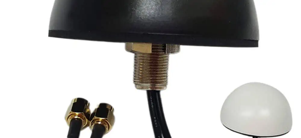
Through hole mount antenna has a stud that can go through an already drilled hole via the surface you are mounting it. This antenna can be mounted in wall panels or ceiling panels. You can mount them on the roof of a vehicle, drywall, and enclosure wall. The stud enables the antenna cable to function due to its hollow center.

Therefore, the cables are just in a side of the surface while the antenna is installed in the other side. Installing a through hole mount antenna involves creating a hole via the mounting surface. The hole must be of a diameter which can contain the stud. The stud must perfectly fit through the hole.

Through hole antennas are also referred to as screw mount antenna or through-hole screw mount antenna. These antennas can direct signal toward the horizon. Due to this, these antennas are suitable for use in applications in flat regions where there are sparse signals. These signals need to cover a large area in such a case.

Furthermore, these antennas have a gasket, washer, and a bolt. All of these help the antenna mount to screw firmly. The gasket seals the hole and as such, protects the cable-side of the antenna from water and the weather. One of the benefits of through hole mount antennas is that they are very rigid and weather proof.

They can withstand any form of shock and vibrations. You can mount these antennas on buildings, vehicles, roofs amongst others. However, you need to ensure the surface you are mounting this antenna on has the appropriate material and thickness in which the mount can screw through. Surface made of materials like plastic, sheet metal, wood, and plastic can accommodate these mounts.

Features of Through Hole Mount Antenna

Through Mount Antenna

Gain: The Gain of this antenna is within the range of 1dBi and 25 dBi. It is ideal to choose an antenna with higher gain since its radiation pattern is effective. Gain describes the extent of the directivity of the radial pattern of an antenna.

VSWR: The voltage standing wave ratio (VSWR) is an important property of the through hole mount antenna. This property reveals the mismatch between this antenna and the feed line. It talks about impedance matching between the transmission line and the through hole antenna. For multiband frequencies, the VSWR of a through hole mount antenna is less than or equal to 3.0, while that of dual band frequencies is less than or equal to 2.0

Frequencies: Through hole mount antennas have various frequencies. These include 900 MHz, 1561 MHz, 698-960 MHz, 433 MHz, 5150-5800 MHz, 868 MHz, and more. The type of frequencies you opt for depends on the requirements of your application.

Direction: These antennasโ€™ directions are omnidirectional. This means that these antennas radiate their signal in all directions. Therefore, they have a wider coverage. Since through hole antennas are omnidirectional, they are great options for wireless networking and transmission.

Polarization: Polarization is an important property of an antenna. When choosing an antenna type, this property is often considered. Just like how VSWR and gain determine a lot in an antenna, so does polarity. Through hole mount antennas are vertically polarized. These antennas feature less loss when you install them close to a side wall.

The method of mounting these antennas is through-hole screw mounted.

Benefits of Through Hole Mount Antennas

As a low profile antenna, the through hole mount antenna offers a lot of benefits. With its distinct features, one can easily tell that this antenna is very beneficial in various applications.

High gain

This antenna has a high gain. It is ideal for use in applications where you need to focus in a preferred direction. Due to this, through hole mount antenna offers better coverage while minimizing low-band congestion. The signal of this antenna goes far, which is beneficial in flat terrain environment.

Durability

As a sturdy antenna, it can stand the test of time. A through hole mount antenna can resist vibration and shock. So, it is a great alternative for various antennas.

Low loss

A through hole mount antenna experiences low loss of energy. Low loss describes the low attenuation or loss of an antenna over distance.

Good impact resistance

This antenna can resist any impact event. Through hole mount antennas have good impact resistance. It can easily withstand intense shock and vibration without experiencing any breaking or damages. Through hole antennas can function well in applications that are exposed to extreme shock.

High efficiency

With its high level of efficiency, through hole antennas have optimized dimensions. Most of the power in the input of through hole mount antenna is usually discharged. Antennas that feature high efficiency discharge a great proportion of the energy applied to it.

Low VSWR

This indicates that through hole mount antennas are well-matched to the feed line. Therefore, more power gets to these antennas.ย  A low VSWR antenna provides an improved impedance match.

Applications of Through Hole Mount Antennas

FULL PCB MANUFACTURING Quote

IoT

In the next few years the Internet of Things (IoT) would connect billions of devices. Low-power and low-cost solution will be the foundation for most applications of IoT devices. Through hole mount antennas for IoT devices must be integrated in the devices or products.

Machine to Machine communication

The IoT ecosystem consists of big part which is the machine to machine communication (M2M). This part of IoT is capable of connecting machines in a cost-effective and easy way. However, the choice of antenna to use in M2M is a controversial topic.

LoRa

Through hole mount antennas are great for LoRa modules due to their low loss and low VSWR. Also, their high gain and good impact resistance is a great benefit for LoRa modules.

GSM

Since these antennas can be easily mounted on roofs and ceilings, they are useful in GSM applications.

Other applications of through hole mount antennas include 2G, 4G LTE, GPRS, NB-IoT, ADS-B, and UMTS.

How to Install a Through Hole Mount Antenna on the Roof

Most times, people complain of damaging their antenna during installation on the roof. If you follow the necessary guidelines, you can easily install a through hole mount antenna without causing any damage to your roof. In all you are doing, avoid drilling holes in the roof to attach the antenna.

Here are spots you can install your through hole mount antenna.

On a gable

The gable is really a good spot to install your antenna as it doesnโ€™t require any drilling of holes in the roof. You can place the antenna very high and direct it at South Mountain.

Chimney

The chimney is another great location to install your antenna. Get a kit that allows you strap the antenna. However, you need to understand that your signal can be interrupted due to ash and smoke. Therefore, this option is ideal if you have no fireplace.

Fascia

Since you may not have a gable or chimney, you can mount the antenna to the fascia. Be sure your fascia is working well and screw in the solid wood. 

Avoid installing your antenna in certain places like plumbing vent. This antenna has a waterproof casing with gasket to prevent water from getting through.

Frequently Asked Questions

How much is a through hole mount antenna?

The cost of a through hole mount antenna varies. Since there are various models of these antennas in the market, cost is determined by these models.

Do through hole mount antennas have various sizes?

Yes, the sizes of these antennas differ. The size of your antenna should depend on the application for which it is intended to be used.

What are the safety standards through hole mount antennas adhere to?

These antennas are compliant to the RoHS or CE standards. Therefore, their safety and functionality have been fully tested.

What range of temperature should through hole antennas be stored?

These antennas have a storage temperature which is within the range of -40 degrees Celsius and +800C. It should be noted that the operating temperature of this antenna ranges between -400C and +850C.

Conclusion

Through hole mount antennas are available in different brands. The type of brand you choose will determine the size and weight of these antennas. As an omnidirectional and vertically polarize antenna, through hole antenna functions well in some applications. Also known as screw mount antennas, these antennas have high sensitivity and optimized dimensions.

What are the Types of RF Filters?

RF Filters

Filters play a very useful role in different aspects of electronics. One important area is the RF or radio frequency domain. These RF filters are useful in accepting or removing signals which fall in some certain radio spectrum areas.

They are useful in different instances. Its application list is nearly infinite. Most times, they are used inside the radio receivers so as to offer selectivity coupled with enabling proper frequencies to enter into the set’s latter parts. Also, they are useful in transmitters to make sure that spurious or unwanted mixers get passed to the following stages. This list continues.

What are RF Interference Filters?

RF Filter PCB
RF Filter PCB

Radio-frequency interference or RFI filters can be described as a circuit or electrical device which mitigates the high-frequency electromagnetic noise that is present on signal and power lines. This high-frequency noise can be generated by different electronic and electrical devices like inverters, power supplies, electronic devices, appliances, microprocessors, clock circuits, etc.

The noise usually falls within the frequency range of 9 KHz and 10 GHz and it could prevent or degrade the transmission of signals and/or electronic/electrical equipment’s performance. Furthermore, the quality of power can be affected by the EM noise’ low-frequency components.

Furthermore, an industrial EMI filter offers low impedance lath to a high-frequency noise. It also reduces it by grounding or canceling its neutral components or line. The EMI/RFI filter effectiveness measures as an insertion loss. EMI filters that are very appropriate for electromagnetic noise fall within a frequency range of 9 KHz and 30 MHz that is conducted via the wires.

Frequencies higher than 30 MHz are radiated requiring shielding as well as output/input isolation. For any radiated frequency, its filter mounting is usually more critical compared to its performance of insertion loss.

You can use the EMI filters widely in applications like Computers, Energy Management Systems, Aerospace/Military subsystems and systems, equipment for factory automation, exercise equipment, MRI rooms, shielded rooms/test chambers, automotive battery charger, medical imaging/patient/diagnostic devices and others.

What are the Types of RF Filters?

RF Filter
RF Filter

Filters come in four main types. Each of the types accepts or rejects signals in different ways. When you make use of the right RF filter, you can accept these signals and then reject the undesired ones. Below are the four main types.

Low pass filters

From the name, rf low pass filters are filters that can only allow lower frequencies through. Typically, it stays nominally flat till the point of cut-off and then rolls off.

The roll off’s actual rate is mainly dependent on what is referred to as the filter’s order. The low pass filter has a very simple principle. It makes use of the principle that a capacitor passes high frequency in order to block any low frequency, while the inductor will pass through low frequency in order to block any high frequency.

For any high frequency which has to be cut off, make use of the capacitor for absorbing the inductance as well as prevent its passing. Also, for any low frequency requiring release, the rf low pass filter makes use of the capacitor’s high resistance characteristics and the inductance’s low resistance to allow it to pass.

High pass filters

In so many ways, they are the inverse of low pass filters. It allows only signals which are higher compared to the cut-off frequencies. Asides from this point, it comes nominally flat and less that the cut off frequency of the RF filter, the response will fall away at a specific rate, which is determined by the filter’s order.

The high pass filter’s features are expressed by first order linear differential equations. Its left side is similar to the 1st order low pass filters. Just the right side is the excitation source’s derivative rather than the source of the excitation itself.

RF Bandpass filters

Rf bandpass filters allow only through signals in specific frequencies. Below and above the cut-off frequency, the signals have to be attenuated as well as within the radio frequency’s accepted band, signals will pass through it.

Band Reject Filters

This opposes the band pass filters because it rejects the signals in a specific radio frequency band. The RF filter form is usually used for removing unwanted signals, which are known to be present in the system.

Classification of RF Filters

The ideal filters whether high pass, band pass or low pass filter would exhibit no loss in the pass band, which is the frequency that is below the usual cut-off frequency. When it is above the frequency which is called stop band, these filters could reject the signals.

Frankly speaking, achieving a perfect pass filter isn’t possible and the pass band usually has some loss within it. Also, achieving an infinite rejection in stop bands isn’t possible. Also between the stop and pass bands, a transition exists, whereby a response curve will fall away, and the rejection level rises as frequency moves from its ass bands into the stop bands.

Filter Technology

One important indicator of the radio frequency filter includes insertion loss and quality factor. In the present communication protocol, differences in frequency between the different bands of frequency are becoming smaller. This is why it requires good selectivity to allow the passband’s signals to pass and then block those signals outside of the passband.

When the Q is larger, the filter’s passband bandwidth will be narrower and then you can achieve better selectivity. Aside from the quality factor, another important parameter is the insertion loss. This deals with the passband signal’s attenuation by the filter, which is loss of the signal power.

Presently, one of the major mainstream methods of implementing the RF filters is BAW and SAW. The rf SAW filter refers to surface acoustic RF filters which make use of piezoelectric effect. Also, whenever you apply voltage onto the crystal, this crystal will pass through mechanical deformation, thereby converting the electrical energy to mechanical energy.

Whenever this crystal becomes mechanically extended or compressed, this mechanical energy becomes converted to electrical energy. The charges will be formed on the two sides of the structure of the crystal. This permits the flow of current through its terminals or creating a voltage in-between the terminals. For solid materials, the mechanical deformations alternative could create sound waves with velocity between 3000 and 12000 meters every second.

Reasons Why the RF Filter is Important?

FULL PCB MANUFACTURING Quote

As applications relating to wireless communication continue to develop, people tend to have higher data transmission speed requirements.

2G

During the 2G period, just a few people used their phones to use the internet as well as browse the web’s WAP version, and the data rate required was around 1 kb per second.

3G

During the 3G period when smartphones became popular, the utilization of networks of operators for sending and receiving emails, as well as the utilization of different applications has led to a sudden increase in the network traffic. The data rate required here is around 50 kb per second.

4G

During the 4G period, applications like live broadcast have greatly increased phone communication’s bandwidth requirements, and the data rate required has gotten to 1 mb per second.

5G

Now, talk of the 5G era, which is just coming in, which requires larger and faster data transmission amounts.

Also, corresponding to the data rate increase is the high use of different spectrum resources as well as the complexity of the communication protocols. Both problems are complementary. This is due to the limited resources of the spectrum, to meet the data rate demand of the people, this spectrum has to be completely used.

This is why a phone should be able to cover a very wide range of frequency so that the devices of different people can be utilized in any crowded situation. Only by this can enough allocation of spectrum bandwidth be possible. Also, in order to meet the requirements of data rate, the technology for carrier aggregation has been utilized since 4G. This ensures that devices can make use of different spectrums for their carrier frequency to help in the transmission of data.

When it comes to RF front end modules, RF filters play a significant role. This could filter the noise and out-of-band interference out in order to meet the radio frequency communication and systems protocolsโ€™ signal to noise ratio requirements.

Furthermore, as we have already mentioned, as communication protocols get more complex, the communication protocol demand outside and inside this frequency band will become higher. This will also make the filterโ€™s design more challenging.

Also, as the frequency bands which mobile phones require to support keeps increasing since every frequency band which mobile phones must support keeps increasing since every frequency band must have a filter, the amount or number of filters required for use in mobile phones is increasing as well.

Conclusion

The significance of RF filters can never be overemphasized. They are useful in different instances. Its application list is nearly infinite. There are four main types. Each of the types accepts or rejects signals in different ways. When you make use of the right RF filter, you can accept these signals and then reject the undesired ones.

Top 10 Hardware Startups in 2023

Hardware Startups

Startups are projected to grow if the team of founders are assiduous with marketing their products and services. Usually, it takes anywhere between 3 and 5 years to determine the lifespan of a startup โ€“ hence, the reason why most startups pack up within this period.

Hardware startups are the rave of the moment, thanks to the increasing demands in computer-related products. In this article, we reveal some of the leading startups that are set to make some impressive moves in the global hardware market.

What is a Hardware Startup?

A hardware startup is a new business that is poised to offer hardware-related services. It is also a techn1. ology company that is focused on the following areas:

  • The delivery of its services in the form of physical electronic devices.
  • The creation of software solutions to enhance the performance of the hardware-related products.
  • Creation of unique and laser-focused products and services designed to serve the needs of a targeted market.

A startup typically gains traction if it offers relatively new products, especially if they could explore creative angles to the promotion. In the hardware market, startups have moved from the conventional design and manufacturing of physical parts and have moved on to offer a plethora of other solutions.

The List of Hardware Startups

Examples of hardware startups are goTenna, Smart Eye and MacroFab. Read this section to the end to find out other top hardware startups to watch out for.

1.    IQM

This startup prefers to be referred to as โ€œthe European leader in quantum computers.โ€ IQM is committed to changing the face of the quantum computing market and making it holistic. This is based on the startupโ€™s resolve to provide quantum computing solutions across different industries, such as supercomputing centers and research laboratories.

Quantum Computing for Europe

The team started the startup based on the decades of research from the Quantum Computing and Devices (QCD) laboratory.

IQMโ€™s goal is to become a leader in the European quantum computing marketing โ€“ a goal it is already working towards by assembling a team of industrial experts from Europe.

On-Premises Quantum Computer

This is one of the startupโ€™s products, designed for the national laboratories and research institutions.

It has the following attributes:

  • Fitted with the required hardware, which is also built around the GPU.
  • The hardware comes with enabled technology leveraged for cryogenic conditioning of both the GPU and the electronics needed for the systemโ€™s operation.

2.    Withings

Everyone deserves access to good health, but it can be expensive. Going for routine checkups requires consistency and this also comes with additional costs. This is why Withings has thrown the hat into the ring to provide sustainable health solutions to the teeming population in the world.

As a healthcare startup, Withings has a single goal โ€“ โ€œbelieving in a world where everyone can see their path to better health, and feel supported to pursue it.โ€

It is this vision that drives the startupโ€™s heavy investments in the production of a variety of healthcare products, ranging from BP Monitors, smart watches and wristbands.

The Withings Products

Withings create technology that chart a better course for the customers to have access to better health. The solutions in this regard include:

ScanWatch

This is one of the startupโ€™s digital health and wellness smart devices. The ScanWatch is designed to be a hybrid smartwatch that makes it simpler to monitor oneโ€™s health. For example, you could use it for a wide range of purposes, including activity tracking, heart health monitoring, sleep analysis and breathing disturbances tracking.

As an advanced health wearable, ScanWatch is what you need to be up-to-date with your health.

Steel HR

This is a clinically-tested hybrid smartwatch with up to 25 days of batter life. It can be used for a near-holistic health monitoring, such as automated sleep monitoring, heart rate monitoring and sports monitoring.

Withings Plus

Withings+ is an advanced, health improvement services, designed to gather and track health-related data. It helps in the following ways:

  • Helping you build long-term, and sustainable health habits.
  • A complete health assessment.
  • Provision of exclusive health content, such as educational articles, recipes and workouts.

3.    CorWave

This is another hardware startup to watch out for. CorWave is in the business of developing innovative heart pumps. The mission is to โ€œprovide solutions to healthcare professionals to save heart failure patients and offer them an active life.โ€

Underlying Technology

CorWave has developed two patent technologies โ€“ CorWave LAD and Nemo. By utilizing the wave membrane technology, the CorWave LAD solution offers the following:

  • Recreating the (systole) ejection and diastole (filling) phases. This is done without necessarily exposing the blood to similar damages triggered by the use of the commercially-available rotary pump LVADs.
  • Preservation of high-fidelity pulsatility.
  • Blood flow restoration.

The CorWave LAD is also designed to provide advanced heart failure solutions via the delivery of an average flow rate of 5 to 6L/min.

The Nemo patent technology is optimized to be an implantable and minimally-invasive cardiac pump. It is designed for the following purposes:

  • Provision of chronic and partial support for patients who are ineligible for LVADs.
  • It is also used to support the heart failure patients who are not currently undergoing treatments.

4.    C12

C12 is a โ€œspin-off from the Physics Laboratory of the Ecole Normale Supรฉrieure in Paris.โ€ It is now poised to power the laboratoryโ€™s promising quantum technology, hence, the dedication to โ€œleading the next materials leap in quantum computing.โ€

Working Processes

The effectiveness of C12โ€™s approach is in the powering the next revolution in computer via the reimagination of quantum hardware development.

Here is how it works:

Qubit Operation

This involves the combination of spins and the C12 hybrid quantum architecture to create high-frequency microwave components and long coherence times. These two aid faster operations in quantum computing.

Ultracapture Carbon Nanotube Growth
FULL PCB MANUFACTURING Quote

This entails the growing of isotopically-pure carbon nanotubes. The nanotubes are designed to contain the 12C isotope of carbon, which helps to suppress unwanted noise from nuclear-electron spin coupling.

Nano-Assembly Process

This entails the use of C12โ€™s patented nano-assembly technology to form quantum circuits via the integration of ultra-pure nanotubes into silicon chips.

5.    Acurable

Acurable specializes in wearable medical device development. These devices are designed to make an accurate diagnose of respiratory conditions and to recommend helpful ways to manage the situation.

The startup has developed quite a number of products to fast-track respiratory conditionsโ€™ management.

Among the products are AcuPebble RE100. It is a wearable device designed to provide the following solutions:

  • A continuous monitoring of breathing and cardiac biosignals for research.
  • Remote measurement of cardiac and breathing signals.
  • Usage of clinically-verified physiological biomarkers and parameters.

The AcuPebble SA100 is an FDA-cleared wearable device for home sleep apnea testing. It is a non-evasive device that also in automating the detection of OSA.

6.    Kinexon

Kinexon is a hardware startup, specializing in the provision of real-time location intelligence for the Internet of Things (IoTs).

The core functionality of the hardware services is powered by the UWB Technology. It is an Ultra-Wideband (UWB) technology that supports the integration of UWB sensors into the consumer electronics. This is also why the range of Kinexon solutions are compatible with Apple watches and Samsung smartphones.

As a localized approach to location intelligence, the UWB technology helps in these ways:

  • Low-power consumption
  • Providing radio-based communication technology for the fast and stabilized transmission of data.
  • It is used to enabling indoor location intelligence gathering for the movement of assets in both the space-constrained and complex environments.
  • Parallel operation with other technologies.
  • Large bandwidth and;
  • Improved security against interception and interferences.

7.    Wallbox

Wallbox is a hardware startup specializing in the development and production of intelligent energy solutions, especially for the Electric Vehicle (EV) market.

Established in 2015, the startup now has a presence of its products in over 80 countries and has office locations in 9 countries.

One of the outstanding products is the public charging stations; an example being the Supernova EV charger. Capable of charging up to 150 kilowatts, Supernova also has a light and modular design that makes public charging of Electric Vehicles (EVs) easier.

Hypernova is another public EV charging solution, capable of charging up to 400 kilowatts. When it is released to the public in 2024, it will bring succor to American EV owners who cannot deal with the current deficiencies in public EV chargers.

Other hardware solutions offered by Wallbox are:

  • Pulsar Plus 48A: this is a compact EV charger that charge any electric-powered car. The features include voice control, adjustable charging capacity and smart performance โ€“ via the use of Bluetooth and Wi-Fi connections to control and monitor the charger.
  • Quasar 2: this is a bidirectional, Direct Current (DC) EV charger. With a compact and versatile design, it allows for easy installation and multiple usage. You could use it to power your electric cars, and power some home appliances in the event of power outage.

Wallbox also makes it EV charging hardware solutions for both individual and multi-usages. These chargers can now be used for the following:

  • Dealerships
  • Multi-unit dwellings and;
  • Fleets

The business or multi-usage option also supports organized charging and power-sharing โ€“ supporting the charging of multiple Electric Vehicles (EVs) at once.

8.    Flow Engineering

Flow Engineering is a startup founded by a group of engineers committed to delivering better solutions to the hardware market. They aim at โ€œproviding the same kind of tools that have revolutionized the software industry.โ€ These solutions would make the development of complex engineering systems, such as autonomous vehicles, launch vehicles, and fusion generators easier.

Here are some of the solutions that will change the traditional engineering methods to a modernized one:

  • Use the Flow Engineeringโ€™s Open API to make a seamless derivation of data across different platforms. Some of the supported tools are Github, Excel, Fusion 360, Jira and Ansys.
  • Provision of advanced IT and compliance solutions. Examples are backup and recovery of customer data, enterprise-grade encryption (using RSA-2048 and AES-256 algorithms), and provision of dual deployment options (On-Premise Software and Compliant Cloud SaaS).

9.    Novelda

Novelda is a hardware startup disrupting the sensor market with the unique offering of UWB sensing solutions. These solutions are powered by the Ultra-Wideband (UWB) short-impulse radar sensors and are optimized to provide an โ€œaccurate, reliable and intelligent sensor solution for human presence detection.โ€

UWB for Everyone and Everything

The Ultra-Wideband (UWB) sensing solutions are available for a wide range of users and applications. From consumer electronics to automating home appliances and building automation โ€“ these solutions are usable across different industries.

The Novelda UWB Occupancy Sensor

RF Hardware Engineer

This is a dedicated sensor for monitoring and reporting even the tiniest of human motions. The Novelda UWB Occupancy Sensor has the following capabilities:

  • Automates the turning off of the lights.
  • Range configuration.
  • Simple integration, thanks to the hardwareโ€™s direct placement on LED circuit boards and the suitability for the pick-and-place engineering processes.

10. ICEYE

ICEYE is the โ€œchoice for persistent monitoring.โ€ Established in 2012, the startup has consistently invested in the development of technology for an all-around monitoring of the earth.

It operates a synthetic-aperture radar satellite constellation, which has been designed to provide robust monitoring capabilities around the earth.

For context, ICEYE takes a pride in offering persistent monitoring via the unlocking of relevant pieces of data through the clouds and at different times in the day.

Access is also offered to the SAR images of the earth โ€“ and this data is provided every few hours in the day.

ICEYE also developed a full range of products and solutions designed to collectively tackle the issues of access, reliability and timeliness, associated with observing data around the earth.

The solutions include:

  • Flood briefing
  • Wildfire monitoring
  • Natural Catastrophe (NATCAT) monitoring and;
  • Flood monitoring.

Conclusion

Hardware startups have a major role to play in the futured growth of our industries. By offering modernized solutions to these industries, they provide real-time resolutions to some of the persistent issues.

The best hardware startups have unique product and service offerings, have excellent marketing strategies for promotion โ€“ and of course, raise adequate funding to make the solutions accessible to the target market.

Flexible PCB Manufacturing in Canada: Fast Prototyping & Low-Cost Production

Flexible Printed Circuit Board Manufacturers

In today’s rapidly evolving electronics landscape, flexible printed circuit boards (flex PCBs) have become essential components for innovative product design. Sourcing these vital components from Canadian manufacturers offers significant advantages for businesses seeking quality, speed, and cost-effectiveness. This comprehensive guide explores why flex PCB Canada suppliers are increasingly becoming the preferred choice for companies needing reliable prototyping and production solutions.

Understanding Flexible PCBs and Their Applications

What Exactly Is a Flexible PCB?

Flexible PCBs are circuit boards manufactured using pliable materials that allow them to bend, fold, and conform to three-dimensional shapes. Unlike traditional rigid PCBs, flex PCBs utilize thin, flexible substrate materialsโ€”typically polyimide or polyester filmsโ€”that maintain electrical connectivity while accommodating movement and vibration. This fundamental difference enables product designs that would be impossible with conventional rigid boards.

The core structure of a flex PCB typically includes:

  • A flexible polyimide base material (most commonly Kaptonยฎ)
  • Conductive copper traces for electrical pathways
  • Protective coverlay or solder mask layers
  • Various surface finish options (ENIG, immersion tin, etc.)

These specialized circuit boards can range from simple single-sided designs to complex multi-layer configurations, depending on the application requirements.

Critical Applications Across Industries

The versatility of flex PCBs has made them indispensable across numerous sectors:

Medical Devices: Canadian-manufactured flex PCBs power life-saving medical equipment where reliability is non-negotiable. From hearing aids and pacemakers to wearable health monitors, these flexible circuits enable miniaturization while maintaining durability in critical applications.

Automotive Electronics: Modern vehicles incorporate dozens of flex PCBs in dashboard displays, engine management systems, and advanced driver assistance systems (ADAS). The ability to withstand vibration, temperature fluctuations, and tight space constraints makes flex PCBs ideal for automotive applications.

Aerospace and Defense: Canadian flex PCB manufacturers support the aerospace industry with lightweight, reliable circuits for satellite systems, aircraft instrumentation, and defense applications where failure is not an option.

Consumer Electronics: Smartphones, tablets, digital cameras, and wearable technology all depend on flex PCBs to achieve their sleek, compact designs while maintaining functionality.

Why Flexibility Matters in Modern Electronics

The demand for flex PCB Canada solutions continues to grow because flexibility offers distinct advantages:

  • Space Optimization: Flex PCBs can fold into compact spaces, enabling 3D packaging that reduces overall device size.
  • Weight Reduction: Critical for aerospace and portable electronics, flex PCBs are significantly lighter than rigid alternatives.
  • Dynamic Applications: Components that must withstand repeated bending or movement during operation require flexible circuits.
  • Improved Reliability: Fewer connectors mean fewer potential points of failure, enhancing overall system reliability.
  • Thermal Management: Flexible circuits can distribute heat more effectively across confined spaces.

Advantages of Choosing Flex PCB Manufacturing in Canada

Quality Standards and Regulatory Compliance

Canadian flex PCB manufacturers operate under stringent quality control systems and regulatory frameworks. Most maintain ISO 9001 certification at minimum, with many also holding specialized certifications for aerospace (AS9100), automotive (IATF 16949), and medical device (ISO 13485) manufacturing.

This commitment to quality translates into several tangible benefits:

  • Consistent manufacturing processes with documented quality controls
  • Regular third-party audits ensuring compliance
  • Traceability of materials and processes
  • Lower defect rates and higher reliability
  • Adherence to international standards like IPC-6013 for flexible circuits

Geographic Proximity and Communication Benefits

For North American companies, partnering with a flex PCB Canada manufacturer offers significant practical advantages:

  • Time Zone Alignment: Real-time communication during standard business hours
  • Reduced Language Barriers: Clear technical discussions without misinterpretations
  • Shorter Shipping Distances: Faster delivery times and lower shipping costs
  • Easier Site Visits: The ability to visit manufacturing facilities for critical projects
  • Cultural Business Alignment: Similar business practices and expectations

Intellectual Property Protection

Intellectual property protection represents another crucial advantage of manufacturing flex PCBs in Canada. Canadian laws provide robust IP safeguards, giving businesses confidence that their proprietary designs and technologies remain secure throughout the manufacturing process.

Fast Prototyping Capabilities for Flexible PCBs in Canada

Accelerating the Design-to-Production Cycle

Canadian flex PCB manufacturers have developed streamlined processes specifically for rapid prototyping. These accelerated services typically include:

  • Online quoting systems for instant pricing
  • Design for manufacturability (DFM) reviews within 24 hours
  • Expedited material procurement for common substrates
  • Dedicated prototyping lines separate from volume production
  • Advanced digital manufacturing techniques

The result is a significantly compressed timeline from concept to functional prototype, with many Canadian suppliers offering turnaround times as quick as 3-5 business days for standard flex PCB prototypes.

Typical Lead Times for Canadian Flex PCB Prototyping

Lead times vary based on design complexity, but general expectations include:

  • Simple single-sided flex PCBs: 3-5 business days
  • Double-sided flex PCBs: 5-7 business days
  • Multi-layer flex circuits: 7-10 business days
  • Rigid-flex hybrid designs: 10-15 business days

These timelines represent a substantial improvement over offshore manufacturing options that often require 3-4 weeks for comparable prototyping services.

Iterative Design Support

Beyond speed, Canadian flex PCB manufacturers typically offer enhanced engineering support during the prototyping phase. This collaborative approach includes:

  • Design optimization suggestions
  • Material recommendations based on application requirements
  • Manufacturability enhancements
  • Testing and validation services
  • Rapid iteration capabilities for design refinements

This level of support proves invaluable for companies developing innovative products with tight market windows.

Read more about:

Cost-Effective Flex PCB Production in Canada

Long-Term Value Proposition

While unit costs for flex PCBs manufactured in Canada may initially appear higher than overseas alternatives, the total cost of ownership often proves more favorable when considering all factors:

  • Reduced Quality Issues: Lower defect rates mean fewer costly reworks and field failures
  • Faster Time-to-Market: Compressed development cycles translate to earlier revenue generation
  • Inventory Management: Shorter lead times allow for leaner inventory practices
  • Supply Chain Resilience: Reduced vulnerability to international shipping disruptions
  • Simplified Logistics: Lower shipping costs and fewer customs complications

Balancing Quality with Affordability

Canadian flex PCB manufacturers have implemented several strategies to remain cost-competitive while maintaining quality:

  • Advanced automation reducing labor costs
  • Lean manufacturing principles minimizing waste
  • Strategic material sourcing and inventory management
  • Specialized equipment optimized for flexible circuit production
  • Energy efficiency initiatives reducing overhead costs

Volume Production Economics

As production volumes increase, Canadian manufacturers offer increasingly competitive pricing structures:

  • Volume discount tiers beginning at modest quantities (often 100+ units)
  • Panel optimization for higher-volume runs
  • Material quantity discounts passed through to customers
  • Dedicated production cells for recurring orders
  • Just-in-time delivery options reducing inventory carrying costs

For many companies, the sweet spot for Canadian flex PCB manufacturing lies in low to medium production volumes (100-10,000 units), where quality, speed, and total cost align optimally.

Essential Selection Criteria for Flex PCB Manufacturers in Canada

Technical Capabilities Assessment

When evaluating potential flex PCB Canada partners, consider these technical capabilities:

  • Layer Count Capacity: Maximum number of layers they can reliably produce
  • Minimum Feature Sizes: Trace width/spacing limitations and via technology
  • Material Options: Range of base materials, adhesives, and surface finishes available
  • Special Processes: Capabilities for selective stiffeners, shielding, or embedded components
  • Testing Infrastructure: In-house electrical testing capabilities and quality verification

Certifications and Standards

Look for manufacturers maintaining relevant certifications:

  • ISO 9001 (Quality Management)
  • ISO 13485 (Medical Devices)
  • AS9100 (Aerospace)
  • IATF 16949 (Automotive)
  • IPC Member certification
  • UL certification for materials

Design Support Services

Evaluate the manufacturer’s ability to support your design process:

  • Design rule checking and optimization
  • Material selection guidance
  • Stack-up recommendations
  • Design for manufacturing (DFM) reviews
  • Design for testing (DFT) strategies

Customer Experience Factors

Beyond technical capabilities, consider these operational factors:

  • Communication responsiveness
  • Project management processes
  • Online ordering and tracking systems
  • Documentation and traceability
  • Technical support availability

Emerging Trends in Flex PCB Technology in Canada

Material and Manufacturing Innovations

Canadian flex PCB manufacturers are advancing the field through several innovations:

  • Ultra-Thin Substrates: Development of reliable circuits using substrates under 25ฮผm
  • Embedded Components: Integrating passive and active components within the flex layers
  • Advanced Adhesiveless Laminates: Improving thermal performance and reliability
  • Additive Manufacturing: Exploring printed electronics for specialized applications
  • Green Manufacturing: Reducing environmental impact through material and process improvements

Growing Demand Across Canadian Industries

Several sectors are driving increased demand for flex PCB Canada solutions:

  • Clean Energy Technologies: Solar panels, wind turbines, and battery management systems
  • IoT Devices: Smart home technology, industrial sensors, and connected infrastructure
  • Advanced Manufacturing: Robotics, automation systems, and smart factories
  • Digital Health: Wearable medical devices and remote monitoring solutions

Canadian manufacturers are well-positioned to support these growth areas with specialized flex PCB capabilities.

Integration with Advanced Electronics

The future of flex PCB development in Canada includes deeper integration with:

  • Microelectromechanical Systems (MEMS): Combining flex PCBs with tiny mechanical elements
  • Printed Electronics: Incorporating printed components directly onto flexible substrates
  • Advanced Interconnect Technologies: Developing high-density, reliable connections between flex and rigid elements
  • 5G and RF Applications: Specialized flex PCBs optimized for high-frequency performance

Conclusion: Making the Right Choice for Flex PCB Canada Manufacturing

The Canadian flexible PCB manufacturing landscape offers compelling advantages for companies seeking reliable, high-quality circuit solutions with fast turnaround times. By balancing quality, speed, and cost-effectiveness, Canadian manufacturers provide a valuable alternative to overseas production, particularly for prototyping and low to medium volume requirements.

When selecting a flex PCB Canada partner, conduct thorough due diligence on their technical capabilities, quality systems, and support services. The right manufacturing relationship can significantly enhance your product development process and contribute to market success.

To begin exploring Canadian flex PCB manufacturing options, request quotes from several qualified suppliers, review their capabilities against your specific requirements, and consider starting with a prototype project to evaluate their performance firsthand.

Frequently Asked Questions

Q: What is the typical turnaround time for flex PCB prototypes in Canada?
A: Most Canadian manufacturers can deliver simple flex PCB prototypes in 3-7 business days, with more complex designs requiring 7-15 business days.

Q: Are Canadian-manufactured flex PCBs more expensive than Asian alternatives?
A: While unit costs may be higher, the total cost of ownership often favors Canadian manufacturing when considering quality, lead time, shipping, and support factors.

Q: What minimum feature sizes can Canadian flex PCB manufacturers achieve?
A: Leading Canadian manufacturers can typically achieve trace/space widths down to 3mil/3mil (0.076mm) and via holes as small as 0.2mm.

Q: Can Canadian manufacturers handle both prototyping and volume production?
A: Yes, most established Canadian flex PCB manufacturers offer seamless scaling from prototype to production volumes, with optimal economics in the low-to-medium volume range.

Q: What design file formats do Canadian flex PCB manufacturers accept?
A: Most accept standard industry formats including Gerber files, ODB++, and native CAD files from common design platforms like Altium, Eagle, and OrCAD.

How to Test Electronic Components on a Circuit Board?

Test Electronic Components

Today circuits have great importance in our lives due to their benefits and features. A circuit comprises different components, and due to this reason, their testing becomes highly important. Therefore testing the parts of a circuit can be done in different ways.

However, you should always opt for the appropriate method. When we test PCBs or other types of circuits, we come to know about their current state and real-time defects.

Testing a circuit needs practice. For the method, we need to get our hands on the specific equipment so that we can drive accurate results from these tests. There are also PCB testing tools like an ohmmeter, a multimeter, and a capacitance meter available that make this inspection feasible for us. We are going to take an extensive look at the testing of circuits and their electronic components in this post.

Stay tuned to find out more and clear your doubts completely as well. 

Resistor testing

Test Electronic Components on a Circuit Board

If you are considering testing the resistors, then you need to stick to some general guidelines. People often mess up the method, and due to this reason, the results are not accurate. Resistors are important in physics. Therefore these are important to test to ensure their fine performance. The resistors have basically two terminals, and their purpose is to resist the current from flowing through a system. We can easily rely on the resistors in special cases. If you want to reduce the chances of current overflow, resistors can help. You will find a huge range of resistors in the market. These differ in pricing and structures. Therefore their potential is different as well. We are going to see how we can test a resistor by using different methods. Letโ€™s get started!

Method 1: 

Visual Inspection

The first method for resistor testing is Visual inspection. You can check the circuits and resistors manually through visual inspection. However, this does not guarantee to point out all the possible defects in the resistors. Check the structure of the resistor. Look for burns, scratches, or if a component has been chipped off.

Look for cracks among the components. Also, see if the components are loosely attached to it. Also, sometimes peculiar color changes of the resistor can indicate problems. If you have extensive knowledge of resistors, a visual inspection can help you with this purpose. However, there are higher chances that VI will not provide positive results in all cases. If a visual inspection does not prove to be handy, you can rely on multimeter testing.

Method 2: 

Using a multimeter

The role of a multimeter is to measure the current, voltage, resistance, and capacitance of a circuit. Therefore you can use it for different measurements. A multimeter will fully test your resistor by giving you accurate readings. Other than this, you need to know how you can use this multimeter for testing your resistor. Before you proceed further, you need to set it to resistor mode. After this, connect its probes to the resistor. Take the reading. If you check the color code of your resistors, it will help you determine the accurate reading. Now compare the given reading with the resistorโ€™s color code.

If the reading matches the tolerance, then there is nothing wrong with your resistor. In case it does not match, then the resistors are definitely defective. A multimeter only works for individual resistors. You cannot test the resistors attached to an existing circuit. Therefore make sure of this in order to get the precise results. In case you have an in-circuit resistor, then detaching it from the setup will be a good option. Once you have tested it, you can go for re-soldering it later. If you find using a multimeter not suitable, then there is another option of using a component tester for inspecting the resistors.

Method 3: 

Component tester

You might find component testing much more interesting than other inspecting methods. What you need to do is that use a component tester and switch it on. After this, place the resistor in its socket. Now push the test button.

The tester will display the reading at once. A component tester displays the reading if there is nothing wrong with your tester and displays โ€œbadโ€ if it’s defective. This is, again, only reliable for the individual resistors. This method is not only quick and easy to use, but you get the results promptly as well. 

Capacitor testing

FULL PCB MANUFACTURING Quote

If you are into physics, then you would know capacitors really well. A capacitor is an electrical component in the devices, and its role is to store energy. Normally, we learn about two basic types of capacitors. One is the electrolytic capacitors, and the other is ceramic capacitors. There is no role of polarity in the performance of ceramic capacitors.

Ceramic capacitors also give you enough room while testing because you donโ€™t have to follow their individual terminals during connection. There are different methods that allow us to test a capacitor. Letโ€™s check them out below:

Method 1: 

Visual inspection

Just like resistor testing, you can test a capacitor through visual inspection. Basically, visual inspection is a common testing method, and experts recommend following it before proceeding with the other techniques. When following VI for capacitor testing, you need to check and identify the structural defects in the capacitor. Also, check the upper side of the capacitor and see if it’s damaged or not. You also need to check for cracks and leakages. It is because these can lead to electrical fires and short circuits later.

You can also look for bumps and dents in the capacitorโ€™s body. Hereโ€™s a fun fact: We assemble capacitors at the front of most of the electronics because they are good at noise-filtering the device. Capacitors are also beneficial in terms of receiving smooth signals and avoiding distortion. There is no doubt that the function of capacitors is intensive, and there are higher chances that these can undergo defects. Therefore VI is a great method to see their real-time issues. In most cases, the capacitors present at the front of the devices are more likely to undergo damage and faults. 

Method 2: 

Multimeter 

As we have talked about it earlier, a multimeter is a good testing tool for off-circuit capacitors. In case you want to test in circuit capacitors, then desoldering them would be reliable. In both cases, you need to follow a proper process for inspection. Or else you will not receive the desired results at all. When we are using a multimeter for testing the individual capacitors, then we need to switch the multimeter to the capacitor mode.

Connect the black probe of the multimer to the negative side while the red probe goes with the positive side. Now you will find a default value of the capacitor mentioned on its structure. You will compare the multimeterโ€™s reading with that value. If the values are alike, then the capacitor is fine. If not, then the capacitor is defective. 

Diode testing

Diodes are important for the routing of the flow of the current. So that the current only follows a single direction throughout the system. Diodes are also good for power supply to the devices. It comprises two terminals and allows the current in a single direction when we have successfully established a forward bias condition. Diodes are important in physics because they are energy-efficient and switch between conditions quite promptly. Therefore, these save time and power at the same time. We can also test diodes through different methods. The details are below:

Method 1: 

Visual inspection

We can start with VI, just like for a resistor and a capacitor. The purpose is to manually check the diode for defects and problems. It can be anything, broken wiring, damaged structure, dents, cracks, and leakage. Some diodes indicate problems through color changes. It means you need to consider an immediate replacement and discard this defective diode as well. Sometimes the terminals of a diode also undergo damage, and their color changes to black. If the diode is heating up often, then it signals a problem.

There are still some problems that can be missed out through visual inspection. It is because when we manually do something, there are chances of human error. In this case, experts recommend using a multimeter. It is a digital diode testing device and leaves no room for error. Therefore relying on a multimeter for diode testing will prove to be effective in this regard. 

Method 2: 

Multimeter

By far, you would have a general idea of using a multimeter for diode testing. Get a multimeter and set it to diode mode. After this, connect the probes of the multimeter with the diode and check it. The reading will give you an idea of the state of the diode.

Now you need to switch the probes and re-connect them to get the final and accurate results. Using a multimeter is handy and quick. Plus, it delivers precise results without making you struggle for accurate readings. 

LED testing

LEDs are nothing but a sort of diode used in different devices. There should be different appliances in your home that have an LED attached to them. Did you know that we can test these LEDs as well? LEDs are diodes, and therefore, these have two terminals. Besides, LEDs are available in different shapes and colors, and you can choose from a wide range of sizes as well. LEDs work with power and glow when we supply power to them.

Circuits that work with LEDs use their colors to indicate different phases. Therefore when a device is ON, its LED will glow, and in case it’s OFF, its LED will not glow. Similarly, if a deviceโ€™s battery is low, the LED will glow in a different color showing that the user needs to charge the device. 

Transistor testing

Transistors are another important physics component that we use in our home appliances and electronics. Transistors are also a part of the latest and innovative technical devices that we often use in our routine lives. It has three terminals in total, and these are variable as per the incoming signals.

You can identify the defects in a transistor by simply using the VI method. It is because the natural shape, performance, and structural quality of a transistor normally give you a general idea regarding its state. Also, you can use another suitable alternative for testing transistors at your convenience. 

Advantages of Component testing

The field of electronics and PCBs both cannot ignore the importance of component testing. It is because a professional PCB producer or an electronics provider deeply understands the significance of component testing for the sake of the safety and quality of circuits and electronics. In this section, we are going to have a look at some of the salient benefits of Component testing for you:

  • It enhances the confidence of a producer in its products
  • It increases the component quality
  • The tested and verified products meet industrial standards
  • The inspected products are more reliable
  • The component testing makes the components safe to use at home
  • The tested components are also durable and show perfect quality 

Conclusion

Electrical components inspection is highly important if we want to produce industrial-grade devices. Any small defect in the abovementioned and other components can incur a big loss not only to users but also tarnishes the reputation of the producers. Therefore, before delivering them, a producer has to make sure that all the components are working fine and are in a perfect state to serve longer.

Testing comes in handy because it saves us from loss of investment. Plus, our devices remain protected from potential damage at the same time. There is no doubt that some testing methods are highly expensive, and high-end producers can think of using them only. However, with a little research, we can learn about affordable alternatives easily. 

Low Temperature Solder Paste: Benefits, Melting Points & Best Uses

Low Temperature Solder Paste

Solder paste is a homogeneous mixture of finely powdered metal solder particles and flux, essential forย printed circuit board (PCB) assembly and manufacturing. Its primary function is to form aย reliable electrical and mechanical bondย between the PCBโ€™s plated connection pads and the mounted components, ensuring a functional circuit. Theย particle size, alloy composition, and flux activityย critically influence the pasteโ€™s performance, directly affecting theย quality and efficiency of the soldering process.

Low-temperature solder pastes also enableย multi-stage assembly processes. In applications where components must be attached sequentially, aย higher-temperature pasteย (e.g.,ย 250ยฐC) can secure the first set of parts, while aย low-temperature pasteย (e.g.,ย 138โ€“180ยฐC) is used in subsequent stages. This ensures the initially placed components remain unaffected during later reflow cycles, preserving their integrity and alignment.

What is Low Temperature Solder Paste?

Low temperature solder paste is a specialized type of solder that melts and solidifies at lower temperatures compared to conventional lead-free or leaded solders. This unique property makes it ideal for use in applications where heat-sensitive components or substrates are involved.

Composition

The composition of low temperature solder paste typically includes a mixture of metals with low melting points. Common alloys used in these pastes include:

  1. Tin-Bismuth (Sn-Bi)
  2. Tin-Bismuth-Indium (Sn-Bi-In)
  3. Tin-Bismuth-Silver (Sn-Bi-Ag)

These alloys are carefully formulated to achieve the desired low melting point while maintaining adequate strength and reliability for electronic connections.

Key Properties

Low temperature solder pastes possess several key properties that set them apart:

  1. Low melting point: Typically ranging from 138ยฐC to 180ยฐC (280ยฐF to 356ยฐF)
  2. Good wettability: Ensures proper adhesion to component leads and PCB pads
  3. Fine particle size: Allows for precise dispensing and printing
  4. Flux compatibility: Often includes no-clean or water-soluble flux for easy post-soldering cleaning

Common Forms

Low temperature solder paste is available in various forms to suit different application methods:

  1. Jars or syringes: For manual dispensing or use with automated dispensing equipment
  2. Stencil printing: Pre-packaged in cartridges for use with stencil printers
  3. Solder wire: For manual soldering applications
  4. Solder preforms: Pre-shaped pieces for specific component types or sizes

Benefits of Low Temperature Solder Paste

The use of low temperature solder paste offers numerous advantages in electronics manufacturing and repair processes.

Prevents Thermal Damage to Heat-Sensitive Components

One of the primary benefits of low temperature solder paste is its ability to protect heat-sensitive components from thermal damage. Many modern electronic components, such as plastic connectors, LEDs, and certain semiconductors, can be easily damaged by excessive heat exposure. By using a solder paste with a lower melting point, manufacturers can reduce the risk of component warping, delamination, or complete failure during the soldering process.

Energy-Efficient

The lower melting point of these solder pastes translates to reduced energy consumption during the soldering process. Reflow ovens and other soldering equipment can operate at lower temperatures, resulting in significant energy savings over time. This not only reduces operational costs but also contributes to a more environmentally friendly manufacturing process.

Easier Rework

When it comes to rework and repair, low temperature solder paste shines. The lower melting point allows technicians to remove and replace components with less risk of damaging surrounding parts or the PCB itself. This is particularly beneficial in densely packed boards where precision is crucial.

Compatibility with Mixed Assemblies

In assemblies that combine traditional and heat-sensitive components, low temperature solder paste offers a solution for uniform soldering. It allows for the simultaneous soldering of various component types without subjecting heat-sensitive parts to potentially damaging temperatures.

Safer for Prototyping

For engineers and hobbyists engaged in prototyping, low temperature solder paste provides a safer alternative. The reduced heat requirements make it easier to work with, especially when using hand-soldering techniques. This can lead to more successful prototypes and a reduced learning curve for those new to soldering.

Read more about:

Melting Points of Low Temp Solder Pastes

Understanding the melting points of different low temperature solder pastes is crucial for selecting the right product for your specific application.

Comparison Table

Alloy CompositionMelting Point RangeCommon Applications
SN42Bi58138ยฐC – 140ยฐC (280ยฐF – 284ยฐF)General-purpose, heat-sensitive components
SN58Bi42138ยฐC – 140ยฐC (280ยฐF – 284ยฐF)Improved strength, slightly higher working temperature
SN48Bi32In20118ยฐC – 135ยฐC (244ยฐF – 275ยฐF)Ultra-low temperature applications
Lead-Free (e.g., SAC305)217ยฐC – 220ยฐC (423ยฐF – 428ยฐF)Standard lead-free soldering (for comparison)

Why Melting Point Matters

The melting point of solder paste is a critical factor in electronics manufacturing and repair for several reasons:

  1. Process compatibility: The melting point determines the required reflow profile and equipment settings.
  2. Component protection: Lower melting points reduce the risk of thermal damage to sensitive parts.
  3. Energy efficiency: Lower melting points generally require less energy during the soldering process.
  4. Rework considerations: Lower melting points facilitate easier component removal and replacement.

Choosing the right melting point for your application involves balancing these factors with the specific requirements of your project.

Best Uses for Low Temperature Solder Paste

Low temperature solder paste finds applications across various industries and projects. Here are some of the best uses for this versatile material:

Electronics Rework & Repair

In the field of electronics repair, low temperature solder paste is invaluable. It allows technicians to remove and replace components on densely packed PCBs with minimal risk of damaging adjacent parts. This is particularly useful in repairing high-value electronics like smartphones, tablets, and laptops.

LED Assembly

LED manufacturing benefits greatly from low temperature solder paste. LEDs are notoriously sensitive to heat, and excessive temperatures can affect their color output and lifespan. By using low temperature solder, manufacturers can ensure consistent quality and longevity in LED products.

Flexible PCBs

Flexible printed circuit boards (PCBs) are increasingly common in modern electronics, from wearable devices to automotive applications. These boards are often made from heat-sensitive materials that can warp or delaminate under high temperatures. Low temperature solder paste allows for reliable connections without compromising the integrity of the flexible substrate.

Medical & Aerospace Electronics

In critical applications like medical devices and aerospace electronics, reliability is paramount. Low temperature solder paste offers a way to create robust connections while minimizing the risk of thermal stress on sensitive components. This can lead to improved long-term reliability in these demanding environments.

Prototyping & Hobbyist Projects

For electronics enthusiasts and makers, low temperature solder paste opens up new possibilities. It allows for easier hand-soldering of surface mount components, which can be challenging with traditional solders. This makes it an excellent choice for prototyping and small-scale production runs.

How to Choose the Right Low Temp Solder Paste

Selecting the appropriate low temperature solder paste for your project involves considering several factors:

Alloy Type

The choice of alloy affects the paste’s melting point, strength, and compatibility with different metals. Consider the specific temperature requirements of your project and the materials you’ll be working with when selecting an alloy.

Flux Core vs. No-Clean Pastes

Flux is essential for proper wetting and oxide removal during soldering. Some low temperature solder pastes come with a flux core, while others are formulated as no-clean pastes. No-clean pastes are convenient for applications where post-soldering cleaning is difficult, but may leave slight residues. Flux core pastes may require cleaning but can offer better wetting in some cases.

Viscosity & Application Method

The viscosity of the solder paste should match your application method. For stencil printing, a slightly lower viscosity is often preferred for smooth deposition. For dispensing applications, a higher viscosity may be necessary to maintain precise control.

Brand Comparisons

While there are many brands of low temperature solder paste available, some popular options include:

  1. Chip Quik: Known for their low-temperature removal alloys and repair kits
  2. AIM: Offers a range of low-temperature alloys for various applications
  3. Indium Corporation: Provides specialized low-temperature solders for demanding applications

Research and compare different brands based on your specific needs, budget, and availability.

Common Challenges & Solutions

While low temperature solder paste offers many advantages, it’s important to be aware of potential challenges and how to address them:

Brittleness

Some low temperature alloys, particularly those with high bismuth content, can be more brittle than traditional solders. This can lead to joint cracking under stress.

Solution: Choose alloys with added strengthening elements like silver, or design joints to minimize mechanical stress.

Oxidation

Low temperature solders can be more prone to oxidation, which can affect joint quality and appearance.

Solution: Use pastes with effective flux formulations and store unused paste properly to prevent oxidation.

Compatibility Issues

Not all component finishes and PCB surface treatments are fully compatible with low temperature solders.

Solution: Verify compatibility with your specific materials and consider surface treatments or alternative finishes if necessary.

Conclusion

Low temperature solder paste has revolutionized many aspects of electronics manufacturing and repair. Its ability to protect heat-sensitive components, improve energy efficiency, and facilitate easier rework makes it an invaluable tool in the modern electronics industry. By understanding its benefits, melting points, and best uses, you can make informed decisions about incorporating low temperature solder paste into your projects.

Whether you’re working on cutting-edge flexible electronics, repairing delicate devices, or prototyping your next big idea, low temperature solder paste offers a versatile solution. As with any technical material, success lies in choosing the right product for your specific application and following best practices for its use.

As technology continues to advance, we can expect to see further innovations in low temperature solder paste formulations, expanding its capabilities and applications. By staying informed about these developments, you’ll be well-equipped to tackle the soldering challenges of today and tomorrow.

Flexible Heater Design, Manufacturing and Types

Introduction

Flexible heaters are versatile heating elements designed to conform to various shapes and surfaces, making them ideal for a wide range of applications across industries. These innovative heating solutions offer numerous advantages over traditional rigid heaters, including improved heat distribution, space-saving designs, and adaptability to complex geometries. In this comprehensive article, we will explore the intricate world of flexible heater design, manufacturing processes, and the various types available in the market.

Flexible Heater Design

Design Considerations

When designing flexible heaters, several factors must be taken into account to ensure optimal performance and longevity:

  1. Temperature requirements: Determine the desired operating temperature range and maximum temperature limits.
  2. Power density: Calculate the required wattage per unit area to achieve the desired heating output.
  3. Substrate material: Select an appropriate flexible substrate that can withstand the operating conditions.
  4. Heating element: Choose the most suitable heating element material and configuration.
  5. Insulation: Determine the necessary insulation to prevent heat loss and ensure safety.
  6. Size and shape: Design the heater to fit the specific application requirements.
  7. Environmental factors: Consider moisture, chemicals, and other environmental conditions the heater may encounter.

Design Process

The flexible heater design process typically involves the following steps:

  1. Requirements gathering: Collect all necessary information about the application, including temperature requirements, power constraints, and environmental conditions.

  2. Material selection: Choose appropriate materials for the substrate, heating element, and insulation based on the gathered requirements.

  3. Heating element layout: Design the heating element pattern to ensure even heat distribution and optimal power density.

  4. Thermal analysis: Conduct thermal simulations to verify the design’s performance and identify potential hot spots or cold areas.

  5. Electrical design: Determine the appropriate voltage, current, and resistance values for the heating element.

  6. Prototyping: Create a prototype of the flexible heater for testing and validation.

  7. Testing and refinement: Evaluate the prototype’s performance and make necessary adjustments to improve the design.

  8. Documentation: Create detailed design specifications and manufacturing instructions.

Manufacturing Processes

The manufacturing of flexible heaters involves several specialized processes, depending on the type of heater being produced. Here are some common manufacturing methods:

1. Etched Foil Heaters

Etched foil heaters are manufactured using a process similar to printed circuit board (PCB) production:

  1. Foil lamination: A thin metal foil (usually copper or nickel) is laminated onto a flexible substrate.
  2. Pattern application: The desired heating element pattern is applied to the foil using photoresist.
  3. Etching: The exposed foil is chemically etched away, leaving the desired heating element pattern.
  4. Insulation: An additional layer of insulation is applied over the etched pattern.
  5. Termination: Electrical connections are added to the heating element.

2. Wire-Wound Heaters

Wire-wound flexible heaters are produced using the following steps:

  1. Wire preparation: The heating wire is wound into the desired pattern.
  2. Substrate application: The wire pattern is placed onto a flexible substrate.
  3. Bonding: The wire is bonded to the substrate using adhesives or vulcanization.
  4. Insulation: An additional layer of flexible insulation is applied over the wire pattern.
  5. Termination: Electrical connections are added to the heating element.

3. Screen Printed Heaters

Screen printed heaters are manufactured using a process that involves:

  1. Screen preparation: A screen with the desired heating element pattern is created.
  2. Ink application: Conductive ink is applied to the flexible substrate through the screen.
  3. Curing: The ink is cured to create a stable heating element.
  4. Insulation: An insulating layer is applied over the printed heating element.
  5. Termination: Electrical connections are added to the heating element.

4. Carbon Fiber Heaters

Carbon fiber heaters are produced using the following process:

  1. Fiber preparation: Carbon fibers are arranged in the desired pattern.
  2. Substrate application: The carbon fiber pattern is placed onto a flexible substrate.
  3. Bonding: The fibers are bonded to the substrate using resin or other adhesives.
  4. Insulation: An insulating layer is applied over the carbon fiber heating element.
  5. Termination: Electrical connections are added to the heating element.

Types of Flexible Heaters

Flexible heaters come in various types, each with its own unique characteristics and applications. Here’s an overview of the most common types:

1. Silicone Rubber Heaters

Silicone rubber heaters are versatile and widely used in many industries.

Characteristic Description
Temperature Range -60ยฐC to 230ยฐC
Flexibility Excellent
Chemical Resistance Good
Moisture Resistance Excellent
Typical Applications Medical devices, aerospace, food service equipment

2. Polyimide (Kapton) Heaters

Polyimide heaters are known for their high temperature resistance and thin profile.

Characteristic Description
Temperature Range -269ยฐC to 400ยฐC
Flexibility Good
Chemical Resistance Excellent
Moisture Resistance Good
Typical Applications Aerospace, electronics, semiconductor processing

3. Polyester (Mylar) Heaters

Polyester heaters offer a cost-effective solution for low-temperature applications.

Characteristic Description
Temperature Range -60ยฐC to 120ยฐC
Flexibility Good
Chemical Resistance Fair
Moisture Resistance Good
Typical Applications Consumer products, automotive, packaging equipment

4. Mica Heaters

Mica heaters provide high temperature capabilities and excellent electrical insulation.

Characteristic Description
Temperature Range Up to 600ยฐC
Flexibility Limited
Chemical Resistance Excellent
Moisture Resistance Good
Typical Applications Industrial processes, laboratory equipment, food service

5. Polymer Thick Film (PTF) Heaters

PTF heaters offer a thin profile and can be easily customized for various applications.

Characteristic Description
Temperature Range -40ยฐC to 150ยฐC
Flexibility Excellent
Chemical Resistance Good
Moisture Resistance Good
Typical Applications Automotive, medical devices, consumer electronics

Applications of Flexible Heaters

Kapton Flexible Heaters

Flexible heaters find applications across numerous industries due to their versatility and adaptability. Some common applications include:

  1. Medical devices: Patient warming blankets, blood warmers, and diagnostic equipment.
  2. Aerospace: De-icing systems for aircraft wings and sensors.
  3. Automotive: Seat heaters, mirror defrosters, and battery warmers.
  4. Food service: Food warming trays and containers.
  5. Industrial processes: Drum heaters, satellite dish de-icing, and pipe freeze protection.
  6. Consumer electronics: LCD displays, touchscreens, and wearable devices.
  7. Scientific instruments: Laboratory equipment and analytical instruments.

Advantages and Limitations of Flexible Heaters

Advantages

  1. Conformability: Can be easily applied to curved or irregular surfaces.
  2. Space-saving: Thin profile allows for use in confined spaces.
  3. Uniform heat distribution: Customizable designs enable even heat distribution.
  4. Fast response time: Thin construction allows for quick heating and cooling.
  5. Customizability: Can be tailored to specific application requirements.
  6. Lightweight: Ideal for applications where weight is a concern.

Limitations

  1. Temperature limitations: Some flexible materials have lower maximum temperature ratings compared to rigid heaters.
  2. Cost: Custom designs can be more expensive than standard rigid heaters.
  3. Durability: May be more susceptible to damage from bending or flexing in certain applications.
  4. Power density: Some types may have lower power density compared to rigid heaters.

Future Trends in Flexible Heater Technology

Flexible Heaters
Flexible Heaters

As technology continues to advance, several trends are emerging in the field of flexible heaters:

  1. Smart flexible heaters: Integration of sensors and control systems for improved temperature regulation and energy efficiency.
  2. Printable electronics: Advancements in printed electronics technology enabling more complex and efficient heating element designs.
  3. Nanomaterial-based heaters: Development of flexible heaters using nanomaterials like carbon nanotubes or graphene for improved performance.
  4. Biodegradable flexible heaters: Research into environmentally friendly materials for disposable or short-term use applications.
  5. Wearable heating solutions: Integration of flexible heaters into clothing and wearable devices for personal comfort and medical applications.

Frequently Asked Questions (FAQ)

  1. Q: What is the typical lifespan of a flexible heater? A: The lifespan of a flexible heater can vary greatly depending on the operating conditions, materials used, and quality of manufacturing. Under normal operating conditions, many flexible heaters can last 5-10 years or more. However, factors such as frequent thermal cycling, exposure to harsh environments, or operation at maximum temperatures can reduce the lifespan.

  2. Q: Can flexible heaters be cut or modified after manufacturing? A: In general, it is not recommended to cut or modify flexible heaters after manufacturing, as this can damage the heating element or compromise the insulation. Some manufacturers offer custom-shapeable heaters that can be trimmed to size, but this should only be done following the manufacturer’s specific instructions.

  3. Q: How do I choose the right flexible heater for my application? A: Selecting the right flexible heater involves considering several factors, including:

    • Temperature requirements
    • Power density needs
    • Environmental conditions (moisture, chemicals, etc.)
    • Size and shape constraints
    • Flexibility requirements
    • Budget It’s often best to consult with a flexible heater manufacturer or specialist who can help you select the most appropriate solution for your specific application.
  4. Q: Are flexible heaters energy-efficient? A: Flexible heaters can be very energy-efficient when properly designed and implemented. Their ability to conform closely to the surface being heated reduces heat loss and improves heat transfer efficiency. Additionally, their fast response times and customizable designs allow for precise temperature control, further improving energy efficiency.

  5. Q: Can flexible heaters be used in explosive environments? A: Some flexible heaters can be designed for use in explosive environments, but this requires special considerations in terms of materials, construction, and certification. If you need a flexible heater for use in a potentially explosive atmosphere, it’s crucial to work with a manufacturer experienced in producing heaters that meet the necessary safety standards and certifications (e.g., ATEX, IECEx) for such environments.

How to Apply the Copper Weight of PCBs Perfectly

Bare Copper PCB

PCBs can be included among some very complicated components of electrical devices. Some things are combined to create a well-functioning PCB. The copper weights are included among the important things that should be properly understood and also micromanaged during the manufacturing of PCBs.

Due to its being an intense conductor, it is highly regarded as one of the important PCB components. Also, if you fail to calculate as well as apply the copper weight appropriately, a lot of things could go wrong.

Measuring as well as calculating standard PCB copper weight isn’t an easy and straightforward process. Also, you will find much information regarding the copper weight PCB available. We will be gathering all the necessary information in this article

What Does PCB Copper Weight Mean?

As mentioned before, copper is a huge conductor. Also, creating a reliable PCB which works and functions consistently without measuring the weight of copper is almost impossible. This is when the question comes up – what does copper weight PCB mean?

Some calculations help in determining the copper weight. This will then be applied to the remaining parts of the printed circuit board as well as connected to every other thing. This PCB is then set for manufacturing after the analyses are correctly performed.

This sounds simple; however, there are some things that should be known regarding copper which contributes to the calculations of copper weight.

Copper as an alloy

Just like other metals, copper is an alloy and this makes it function as a conductor. You can find alloys in different forms. However, copper is regarded as the most common during PCB construction.

Alloys can come in the tube, sheet, or bar form. This is the first thing you have to consider before you determine the PCB copper’s weight. Understanding the form and grade copper takes are just two of the things that help in calculating the base copper weight. The remaining pertains to the physical measurements that involve copper itself.

Also very important, is that these measurements and calculations have to be perfect. When you fail to do this, it doesn’t mean significant problems, it means you have to return and remeasure things which will take long and be very stressful.

The worst scenario is applying copper into the PCB after you’ve made some wrong calculations. For cases like this, undoing what was done becomes difficult and could be impossible.

Use of Heavy Copper in PCB Design Considerations

Ok the last section, we discussed the PCB copper weight. Here, we will be exploring the use of heavy copper in enhancing PCB design.

Heavy copper could have a thickness of 19 ounces for every square foot. This makes it a well-known option for many printed circuit boards since the majority of the electronics of today are smaller compared to electronics used in the past.

Although other copper sizes can still be used, heavy copper is now the most popular and most common. With heavy copper, you get more options for your PCB design. PCB manufacturing and design experts have found ways of improving the looks of printed circuit boards because of the high versatility of heavy copper.

Also, copper is only responsible for small spaces on circuit boards in PCB manufacturing. With this, it becomes possible to make circuit boards which function effectively and look more desirable that usual.

As a result of this, you can now create artworks from PCBs like this. Achieving this isn’t as difficult as you think. This requires great understanding of the copper weights, measuring as well as weighing copper, coupled with some soldering techniques.

Specifications of the PCB Copper Weight

FULL PCB MANUFACTURING Quote

In this section, we will be considering the specifications of the PCB copper weight. Copper has three main weight classes. Every one of these classes is useful in circuit board manufacturing. The pcb copper weight to thickness can be measured in ounce per sq ft.

Since copper is a strong conductor, which yields predictable mils and amps, measuring it for every square inch is not necessary. It ensures the accuracy of other calculations.

Standard Copper

Standard copper can be described as copper having a plating of a quarter of an ounce for every square foot to about four ounces for every square foot. This used to be the industry standard (defacto) for the building of all PCBs for long periods, as there was a risk of failure whenever it is used for plating printed circuit boards.

In so many cases, standard copper is still used. When a specific copper size isn’t specified, many distributors of materials would assume the manufacturer wants 1.2 ounces for every square foot copper plating.

Heavy Copper

Heavy copper can be described as any copper that is between 5 โ€“ 10 ounces for every square foot. Designers and testers have utilized heavy copper over the years for experimenting their designs. Today, you can now create a printed circuit board using heavy copper and in most cases, it is better, compared to the standard copper.

Over the years, this was seen as a risky approach, because many people believed that copper was a very strong conductor and shouldnโ€™t be plated on circuit boards without a terrible result.

This has been proved wrong recently, because lessening the chargeโ€™s amp value produced from the heavy copper is possible. This is achieved by exposing this copper before it is plated on a surface.

Conclusion

In summary, copper is an intense conductor and it is highly regarded as one of the important PCB components. Also, if you fail to calculate as well as apply the copper weight appropriately, a lot of things could go wrong. Alloys can come in the tube, sheet, or bar form. This is the first thing you have to consider before you determine the copper weight pcb. Understanding the form and grade copper takes are just two of the things that help in calculating the base copper weight pcb. Also, measurements and calculations have to be perfect. When you fail to do this, it means you have to return and remeasure things which will take long and be very stressful.

Top 10 Hardware Manufacturing Companies

RF Hardware Engineer

The world is called a โ€œconnected communityโ€ because of the role played by the Internet. We have the Internet today because of the availability of the devices used for accessing it. From computers to smartphones โ€“ a lot of devices are now Internet-enabled.

Hardware drives the performance of most of these devices. To this end, the global hardware is one of the most profitable with the top 10 hardware manufacturing companies leading by the market capitalizations.

What is Hardware?

Also called computer hardware, the term โ€œhardwareโ€ is used to describe the physical computers of a computer. It is also used to refer to the related devices used in a computer.

To this end, a hardware manufacturing company specializes in the production of the tangible or physical components of a computer, and which are required for enhancing the softwareโ€™s operations.

What Types of Hardware Exist?

hardware development

Different hardware manufacturing companies produce a variety of hardware. Generally, they are categorized into internal and external hardware.

While the external hardware deals with the outward computer components, such as printers, keyboards, scanners, and monitors; the internal hardware is for the components inside the computer. Examples of these components are power supplies, motherboards, Random Access Memories (RAMs), graphic cards, Hard Disk Drives (HDDs), and Solid-State Drives (SSDs).

Now, we are going to talk about some of the top hardware manufacturing companies and some of the services they offer in that regard.

1.    Apple

When a mention is made of the companies that produce the most hardware, Apple tops the list. Besides having diverse products in this regard, the company also has a dominating market share that makes it the leading company, by market capitalization.

As a leading tech hardware company, Apple produces a range of household devices, ranging from mobile communication devices (such as iPhones and iPads); digital watches, Personal Computers (such as Macs) and portable digital music players.

To bolster the services, the company also offers a plethora of other related services, such as:

  • Music and streaming entertainment solutions.
  • Networking solutions.

2.    Samsung

Samsung Electronics prove that the tech hardware market is not limited to a country. While Apple is dominating in the U.S. where it is based and other parts of the world; Samsung created a new market in the South Korean region.

This South Korean hardware manufacturer is also a household name, thanks to the classy design of the hardware solutions. Today, you can enjoy the consumer and industrial computer hardware solutions the company offers.

A Fierce Competitor to Apple

Samsung Electronics favorably competes with Apple in the global hardware market. For example, the Galaxy series of smartphones are a direct competition to Appleโ€™s iPhones.

On the other hand, the production of computer peripherals, such as hardware makes it a global brand. Samsung Electronics manufacture the following:

  • Digital cameras
  • Personal Computers (PCs)
  • Monitors and;
  • Semiconductors

3.    Intel Corporation

Intel Corporation or Intel for short, is an American electronics company specializing in the design, production and sells of computer parts. It majors in the manufacturing and selling of microprocessors (especially the x86 microprocessor, which most electronicsโ€™ manufacturers purchase from Intel).

Intelโ€™s offerings in the semiconductor market also covers memory devices, motherboards, power solutions, and chipsets.

Intel Corporation also has a suite of hardware solutions, such as:

AI-Related Hardware Solutions

In the dawn of Artificial Intelligence (AI), Intel has delved into the production of different kinds of hardware to satisfy the market demands. The suite of AI hardware solutions includes:

  • Habana Gaudi and Goya: these are hardware solutions designed drive the efficiency and deep learning performance on the cloud and datacenters.
  • Intel Xeon Scalable Processors: these are dedicated processors for accelerating AI and security capabilities. These processors also come in handy for the simplification of the datacenter AI deployments.
  • Intel GPUs: these are Xe architecture integrated into future-discrete GPUs and selected Central Processing Units (CPUs).

Hardware for Edge Workloads

Intel also produces hardware used to test the workloads for a wide range of combinations, such as accelerators, CPUs and GPUs. These are broadly used to identify the best architecture for fitting your hardware needs on the Intel Developer Cloud for the Edge development environment.

4.    HP Inc.

FULL PCB MANUFACTURING Quote

HP is one of the popular names in the global hardware market. As a multinational Information Technology (IT) company, it specializes in the production and distribution of printing and image-related solutions for the computer hardware market. From printers to scanners, toners and printing inks โ€“ HP makes them all.

The manufacturer also deals on other extensive areas of hardware, such as:

  • Storage solutions.
  • Workstations.
  • Personal Computers (PCs).
  • Consumer desktop and notebooks.
  • Scanning devices and;
  • Audio devices.

5.    Lenovo Group

This is a Hong-Kong hardware manufacturer, specializing in the design, development and production of different kinds of computer-related solutions, including hardware.

Anything from tablets, servers, workstations, smart TVs, PCs and smartphones are the companyโ€™s forte.

Besides these, it also specializes in the provision of Information Technology (IT) and Internet-related services.

6.    Dell Technologies

Also called Dell for short, this is a holding company that provides innovative and extensive solutions for the hardware market.

Dell specializes in the provision of hardware and software solutions, targeted at the Information Technology (IT) sector.

Hardware Solutions

Dell provides different kinds of hardware solutions, such as storage and PCs. For the storage solutions, it provides the PowerStore, which is geared towards introducing a โ€œfuture-proof intelligent storage that redefines performance.โ€

It also offers scalable IT solutions, designed to provide a power transformation with networking, storage and server solutions. These are further made adaptable and scalable, as per your businessโ€™ needs.

The desktops are optimized along the lines of minimalism, simplicity and maximum performance. The Optiplex monitors, for example, are Artificial Intelligence (AI)-driven desktops with simplified design and upgraded performance.

7.    Cisco Systems Inc.

This hardware manufacturing company produces and sells a plethora of hardware products for the networking devices.

Examples of the products in the portfolio are network management solutions, such as controllers, switches, and routers.

Cisco also manufactures interfaces and modules, such as:

  • Cisco Optical Transponders
  • Cisco Network Modules
  • Cisco Services Modules
  • Cisco Interface Cards and;
  • Cisco Nexus SmartNIC

Cisco Webex Hardware

This is Ciscoโ€™s hardware-as-a-service solution, deigned to improve the use of latest technologies for increasing collaboration in the workplace.

With the Cisco Webex Hardware as a Service subscription, you get to:

  • Make your workplace devices adaptable.
  • Enjoy industry-leading collaboration endpoints, especially via the connection of Webex-enabled devices and IP phones.

8.    Nvidia Corporation

This is an American multinational IT company that has in recent years, become a leader in the Artificial Intelligence (AI) computing market. Nvidia is gaining this status due to the massive investments in the production of hardware for AI solutions.

The Motley Fool had listed the Nvidia stock as one of the best to buy if you are looking to invest in AI-related stocks.

Nvidia is popular for the different kinds of graphics cards it manufactures, especially those used in the gaming laptops. A good example is the GeForce RTX 40 Series Graphics Cards popularized for the quantum leap they offer in terms of performance and providing AI-powered graphics.

Nvidiaโ€™s AI Computation Solutions

The hardware-related solutions for Artificial Intelligence (AI) advancements cut across different areas, such as high-performance computing, design and simulation, robotics and edge computing, AI and data science, gaming and creating; and automotive markets.

The NVIDIA Isaac and Jetson platforms are specifically used for developing and delivering end-to-end solutions for the robotics and edge computing markets. These platforms also aid the delivery of the Nvidia hardware solutions to the retail, manufacturing, smart cities, logistics and healthcare markets.

The company also deploys the hardware solutions for the High-Performance Computing (HPC) solutions. Here, the solutions are enabled to process data and perform a wide range of complex calculations at faster speeds.

9.    LG Electronics

LG is one of the top manufacturers of hardware used in the production of home appliances. Based in South Korea, it has remained consistent with the production and sales of home appliances and a wide range of digital display equipment.

It is worth noting that LG Electronics also manufactures telecommunication gadgets.

The list of products it manufactures covers:

  • Tablets
  • A/V products
  • Smartphones
  • LED lighting
  • Personal Computers (PCs)
  • Air conditioners
  • Flat panel TVs and;
  • Washing machines.
  1. SONY

This is a Japanese hardware manufacturing company that specializes in making components for game consoles, electronic pieces of equipment, software, smartphones and instruments. SONY also manufactures camera modules, Personal Computers (PCs), image sensors and audio systems.

How to Choose the Best Hardware Manufacturer

Although the likes of LG Electronics, Dell, HP, Apple, Cisco and Samsung made the list; they are not the only hardware manufacturers in the world.

Other companies are Panasonic, Hon Hai Precision Industry, SONY, Tedco Precision Sheet Metal, Keystone Electronics Corporation, Device Technologies, Inc., and GracileIT.

If you are to work with any of these companies, you must first consider their capabilities. Here are some of the key points to help you make that decision:

What Type of Hardware Does the Company Make?

There are two major categories of hardware. These are the internal and external hardware. You want to choose the best hardware manufacturer based on the capabilities or specialty in making one or more of these parts.

Internal Hardware Components

As the name signifies, these are the parts inside the computer. The internal hardware components are basically used to process and store information or a set of instructions. Examples of such instructions are delivering the Operating System (OS) and programs.

Below are some of the examples of internal hardware parts:

  • Card Readers: these are used to enable the โ€œreadingโ€ of data from portable storage devices, such as Memory Cards (MCs).
  • Central Processing Units (CPUs): these are responsible for processing the data from the computer-run programs.
  • ODD: the Optical Disk Drive (ODD) is a type of storage device used to read and write data into optical disks. The process for actualizing this is via electromagnetic waves.
  • Network Interface Cards (NICs): these are the interface cards that allow the computer-to-network connection to hold. The exchange of information or data between the computer and the Internet (network) is enabled via the NICโ€™s controlling of the computer systemโ€™s wired and wireless connections.
  • RAM: the Random-Access Memory (RAM) is a storage component used for temporally storing the data created by the programs run by the computer systems.
  • SSD: this is another type of storage device. The Solid-State Drive (SSD) is a flash drive-like of device that accesses data faster and uses less power when compared to the HDD.
  • HDD: the Hard Disk Drive (HDD) provides the main storage for computer systems. It is also used to provide permanent storage of the data, especially when there is power outage in the computer systems.

External Hardware Components

These are the hardware parts on the outer surface of the computer systems. They are connected to the computer systems as a way of providing either outputs or inputs.

The external hardware components, also called โ€œperipherals,โ€ include:

  • Headphones: these are used for listening to audio in the computer systems.
  • Mouse: the work of the mouse is to aid the control of objects on the computer systemsโ€™ screens.
  • Printers: you can use these to generate the hard copies of the pieces of electronic data stored inside the computer systemsโ€™ internal storage systems, such as HDDs and SDDs.
  • Flash Drives: the Universal Serial Bus (USB) flash drives are make a portable storage of data.
  • Monitors: these are used for delivering the graphics and video information of the computer systems.
  • Webcam: depending on the computer systems, the web cameras (webcams) can either be embedded or integrated into the computer or provided as an attachment, connectable via a USB. The function of the webcam is to produce motion videos and still pictures via the connection to the computer and the Internet.

Final Words

Hardware components continue to drive the ongoing innovations of Information Technology (IT). Using the right components makes all the difference in your electronicsโ€™ performance.

Top manufactures like Intel, Dell, LG Electronics, Apple, Cisco and HP Inc. have distinguished themselves with the variety of solutions they offer.

When choosing one of these companies, ensure to verify the adaptability of their hardware solutions to your immediate needs. This way, you donโ€™t waste money and time buying hardware that doesnโ€™t provide the expected value.

What Is RF Coaxial Cable? Everything You Need To Know

RF cable

Coax cables or coaxial cables are for seamlessly transmitting and receiving signals between different terminals. The RF coaxial cable holds great importance in telecommunications. Not only this, there are many other fields that find coax cables useful.

The purpose of these cables is to act as a bridge between satellites and bring their signals to homes and offices, which makes online surfing and browsing possible in our lives.

These cables are highly reliable and serve in the long run as well. We are going to make it interesting for you to learn about the coax cables in detail. So that if you have any confusion about RF coax cable, you can kick it out of your brain today!

Ready to dive in? Here we go!

Working on Coaxial Cables

Coaxial cables have an interesting phenomenon of working. These are reliable to choose from because of their sturdy design. They consist of a conductor which acts for data transmission effortlessly. The coaxial cables are important to consider because they are more likely to remain protected from potential damage and problematic interface. The conductor of the coaxial calves is present in the center, which is why these cables are able to carry data. The other layers are for reducing the signal loss and also lowering the EMI. These coax cables are made of 4 important layers in total. We are going to learn about them briefly below:

  • The central layer is made of copper for the transmission and video-based content and critical data.
  • On this copper layer, the second layer is of dielectric plastic insulators that also have important roles.
  • The third is a braided mesh also made of copper, which acts as the protection of the coaxial cable structure from the harmful impact of EMI.
  • The outermost layer of a cable is plastic, and its role is to protect all the internal layers from possible risks and damage.ย 

Major Types of Coaxial Cablesย 

TYPES OF COAXIAL CABLES

Since technology is empowering different domains around us, there are different kinds of coaxials available in the market. However, there are two main divisions of coaxial cables. One group of them has a 75-ohm impedance, and the other group has a 50-ohm impedance. The 75-ohm cables are beneficial for video signaling, while others are for wireless communications and transmission of critical data. 

1.    RF coaxial cable

These are highly important for RF signals and make the satellite connections work with the least effort. Also, these are suitable to connect with the TVs and also work with an individual pin that joins with the electronic devices. 

2.    RG-6 cable

It comes with huge conductors, and due to this reason, these are more precise in maintaining signal quality. These cables also have thick insulation and provide impressive shielding at the same time. These are important to consider when we consider Giga hertz signals. You can even insert it easily in congested areas like ceilings and walls. 

3.    RG-59 cable

These are another typical type of coaxial cable available for different applications. These are somewhat like RG-6; however, their design and structure are much slimmer than the others. Such coaxial cables are crucial for short-term transmission and with very little frequency data transmission as well. 

4.    RG-11 cable

These are also common because of their thick and durable design that renders different benefits. However, despite the fact that it is beneficial, it is not easy to handle them and position them as per your will. These are beneficial for long-term and critical data transmission. 

5.    RF Cables

Do you ever wonder how does your TV perform in your life? Well, it is interesting and coaxial cables play a big role in its performance. The RF coaxial cables basically take the data to our TV sets. These are beneficial to work with the RF signals, and this is how our TVs actually work. These signals can be used by any electronic device other than a TV. Wireless communication and critical applications rely on coaxial cables and RF cables for fine performance. Itโ€™s time to head over to the major benefits of RF cables that we dont consider. Take a look:

Benefits of RF Cable

The goal is to rely on an industrial grade and a standard RF cable so that it will serve in the long run. These cables are more likely to offer major benefits instead of cheap quality cables. Therefore, their applications become more integral, whether these are in the medical sector, aerospace, or defense. The major benefits of RF cables are:

  1. Promise less signal-loss
  2. More reliable due to the aluminum layer
  3. Enhanced connections 24/7
  4. Versatile nature and multiple applications

Identification of RF Cables

As you know, there are different types of coaxial cables available out there, so how do you find the best fit? It becomes difficult to find the perfect match. Due to this reason, there are some factors that will help you find the perfect match each time. Take a look at these below:

  1. It should have connectors at the end terminal
  2. The connectors should have a single pin 
  3. The round metal should be attached to the RF cable where the input port is 

RF Cable vs. Coaxial cable

Since we have learned about RF cables and coaxial cables, it is obvious that their applications and features are also different. For this reason, it is highly important to understand the differences between the both. So that you will be able to drive positive results from these cables, now letโ€™s see what are the major differences between the two.

  • RF cables are for working with the signals that transmit at radio frequency
  • Coaxial cables are for transmitting the signals for the electronics like TVs and radios
  • Coaxial cables are usually thicker than RF cables as well 
  • RF cables transmit throughout the cable, unlike coaxial cables that use their center for the same purpose
  • Coaxial cables have a relatively thicker insulative layer present inside, unlike RF cables

We just talked about the thicker insulative layer of coaxial cables; there is a reason behind it. The reason is the befits of this layer. This is how the insulative layer benefits the coaxial cables:

  • It lowers the EMIโ€™s influence on the signal transmission
  • It also lowers the loss of signals 

Working on RF Cables

The process of working RF cables is different from coaxial cables. Take video installations, for example. These cannot work without RF cables. Formerly, people used to think these could only carry analog signals, but this is not true. RF cables are more capable, and this is why their importance is undeniable. 

Like (CATV) systems, RF cables carry the following:

  • These transmit Broadband cable internet 
  • High-bandwidth digital cable content is also possible with RF cables 

The RF cables are not only beneficial in high-frequency signal transmission but are also crucial for the low-noise block converter, but it is always placed away from the receiver of the satellite. Due to this reason, it arises the need for a suitable cable; however, it has to meet some requirements:

  • Its capacitance should be less.
  • It should have tight impedance stability. 

RF Cable for TV

FULL PCB MANUFACTURING Quote

Now you have got the RF cable, how are you going to connect it to your TV antenna? Dont worry; we are going to make it easier for you. Make sure the cable is large so that there will be no mishaps in the signal transition at all. You need to take the cable to the antenna and connect it. However, there are two ways that you will start receiving HD quality content from your TV in terms of music and video-based content. 

HDTV Output & output

When we are working with RF cable, it is important to follow the correct way for the connection. Many users fail to understand this, and due to this reason, they fail to connect the RF cable to their TVs. This is how you can connect the RF cable to the TV:

  1. Join the cable to your TV through the port that says โ€œcable in.โ€
  2. Now join the โ€œcable outโ€ with the โ€œTV inputโ€ port.
  3. If the receiver has the S-video output, you can generate more analog videos on your TV, so join it with both the receiver and the TV.
  4. Make sure the component cables of your TV are in place and insert them in the individual slots carefully. 

RF cable to HDMI

You can even connect the RF cable to the HDMI cable, and there is a correct way of doing this:

  • Take one end of the HDMI cable and join it with the HDMI box.
  • The other end goes with the TV input HDMI
  • The converter will change the RF analog signals into a digital signal
  • HDI will transmit audio and videos for the digital TV 

Since there are different RF cables present in the market, there are more chances of scams and fraud. Therefore, you need to get your hands on the best RF cable to produce great results from it. You can even check online stores for this purpose or consult a credible and certified nearby supplier. 

Summary

The right choice of an RF cable is important when you are looking for the desired results. It is because cheap quality RF cables not only put your devices at risk but lead to the ultimate waste of investment. These cables are famous and durable because of their thick insulation and impressive performance in terms of signal transmission. Their lifespan is also longer than the other types of cables, and due to this reason, these are user-favorite types of cables. We have 

discussed some of the important aspects of RF cables for you and even compared them with coaxial cables. Now you can make a wise choice!