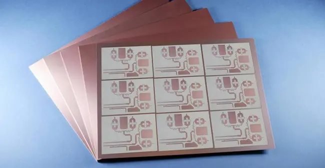
Rogers RO3000 Series are high-performance circuit materials for RF and microwave applications. These ceramic-filled PTFE composites offer low dielectric constants and loss tangents. Detailed specifications are available in the product datasheet. While prices vary based on specific grade and quantity, they’re competitively priced for their performance level. The series includes popular grades like RO3003 and RO3006, each optimized for different frequency ranges and applications.
RO3003 Laminates are high-frequency circuit materials from Rogers Corporation. They offer a low dielectric constant of 3.0, excellent electrical performance, and tight thickness tolerance. These ceramic-filled PTFE composites are ideal for millimeter-wave applications, antennas, and precision stripline circuits.
RO3003G2 Laminates are advanced circuit materials designed for high-frequency applications. With a low dielectric constant of 3.0, they offer excellent electrical performance, low loss, and superior dimensional stability. Ideal for millimeter-wave circuits, antennas, and precision stripline designs.
Next generation laminates for 77/79 GHz auto radar designs
Very low profile ED copper for lower insertion loss
Formulated to minimize Dk variation & enable micro vias
RO3006 Laminates are high-frequency circuit materials engineered for RF and microwave applications. With a dielectric constant of 6.15, they provide low loss, excellent dimensional stability, and consistent electrical properties. Ideal for antennas, filters, and high-speed digital circuits.
RO3010 Laminates are high-performance circuit materials designed for RF and microwave applications. With a dielectric constant of 10.2, they offer excellent electrical stability, low loss, and tight thickness control. Ideal for compact antennas and filters in wireless communication systems.
RO3035 Laminates are high-frequency circuit materials designed for microwave and RF applications. They offer excellent electrical performance, low loss, and consistent dielectric constant. These laminates are ideal for antenna systems, power amplifiers, and other demanding high-frequency circuits.
RO3200 Series Laminates are high-performance circuit materials by Rogers Corporation. These ceramic-filled PTFE composites offer a dielectric constant of 3.0 to 3.5, low loss, and excellent dimensional stability. They’re ideal for high-frequency, low-noise amplifiers and space-saving multilayer boards.
Rogers RO3000 Series Laminates – PSIS are high-frequency circuit materials designed for demanding RF and microwave applications. These ceramic-filled PTFE composites offer excellent electrical and mechanical stability across a wide range of frequencies. With low dielectric constants and loss tangents, they’re ideal for antenna arrays, power amplifiers, and patch antennas. Their consistent performance and ease of fabrication make them popular choices in the telecommunications and aerospace industries.
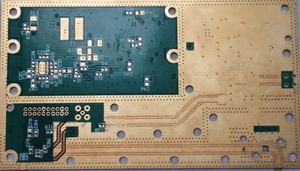
PCB Materials for Handheld Device Antennas are specialized substrates designed to optimize wireless performance in compact electronics. These materials offer low dielectric loss, consistent electrical properties, and thermal stability. They support high-frequency operations, minimize signal interference, and maintain antenna efficiency. Used in smartphones, tablets, and wearables, these materials enable miniaturization of antennas while ensuring reliable connectivity. Their properties contribute to improved signal quality, extended battery life, and enhanced overall device performance in the competitive handheld electronics market.
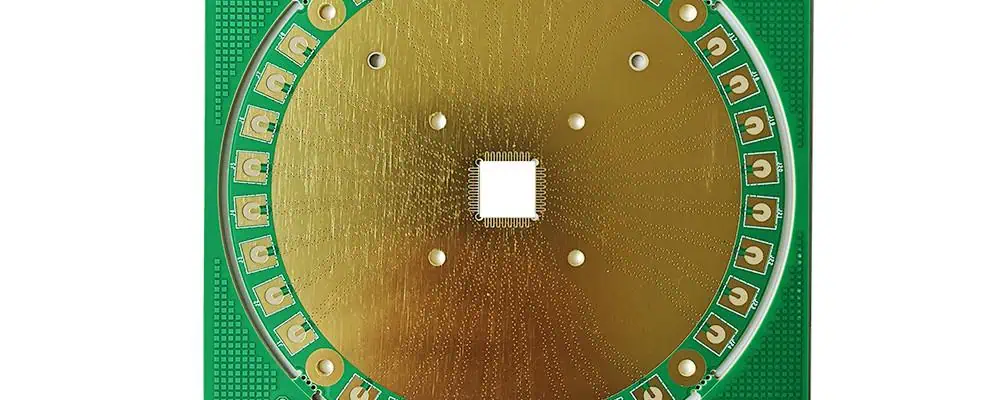
High Performance Automotive Circuit Materials are specialized substrates designed for electronic systems in vehicles. These materials offer superior electrical properties, thermal stability, and reliability under extreme conditions. They support high-speed data transmission, resist electromagnetic interference, and withstand vibrations and temperature fluctuations. Used in advanced driver assistance systems, infotainment, and powertrain control modules, these materials enable lighter, more efficient, and technologically advanced vehicles, meeting the demanding requirements of modern automotive electronics.
Powered By EmbedPress
High Performance Automotive Circuit Materials – Paving the Way
The automotive industry stands at a technological crossroads, where traditional mechanical systems are rapidly giving way to sophisticated electronic architectures. As vehicles evolve from simple transportation devices to complex mobile computing platforms, the demand for high-performance automotive circuit materials has never been more critical. These specialized materials form the backbone of modern automotive electronics, enabling everything from basic engine management to advanced autonomous driving systems.
The Evolution of Automotive Electronics
Modern vehicles contain an astounding array of electronic systems that would have been unimaginable just decades ago. Today’s average car incorporates over 100 electronic control units (ECUs), managing functions ranging from powertrain control and safety systems to infotainment and connectivity features. This electronic proliferation has created unprecedented demands on the circuit materials that support these systems.
The transition toward electric and hybrid vehicles has further intensified these requirements. High-voltage battery management systems, electric motor controllers, and regenerative braking systems all demand circuit materials capable of handling extreme electrical loads while maintaining reliability over extended periods. Additionally, the push toward autonomous driving technologies requires circuit boards that can process vast amounts of sensor data in real-time, necessitating materials with exceptional signal integrity characteristics.
Critical Performance Requirements
Automotive circuit materials must meet stringent performance criteria that far exceed those of consumer electronics. Temperature resilience stands as perhaps the most demanding requirement, as automotive electronics must function reliably across temperature ranges from -40°C to +125°C, with some applications requiring even broader ranges. Under-hood components face particularly harsh conditions, experiencing rapid temperature cycling, vibration, and exposure to automotive fluids.
Electrical performance requirements are equally demanding. High-frequency applications, such as radar systems for collision avoidance and adaptive cruise control, require materials with stable dielectric properties and minimal signal loss. Power electronics applications demand materials capable of handling high current densities while maintaining thermal stability. The increasing prevalence of high-speed digital communications within vehicles necessitates materials with controlled impedance characteristics and minimal electromagnetic interference.
Mechanical durability represents another critical performance dimension. Automotive circuit boards must withstand constant vibration, thermal cycling, and mechanical stress throughout the vehicle’s operational lifetime. This durability requirement extends to the material’s ability to maintain solder joint integrity and resist delamination under stress.
Advanced Material Technologies
The industry has responded to these challenges through the development of specialized high-performance materials. Modern automotive circuit materials typically employ advanced resin systems, such as modified epoxy resins, polyimides, and thermoplastic materials, each offering unique advantages for specific applications.
Thermally conductive materials have gained prominence in power electronics applications. These materials incorporate thermally conductive fillers, such as aluminum oxide or boron nitride, to enhance heat dissipation while maintaining electrical insulation properties. Metal-core printed circuit boards (MCPCBs) represent an extreme example of this approach, featuring metal substrates that provide exceptional thermal management capabilities for high-power LED lighting and power conversion applications.
For high-frequency applications, low-loss dielectric materials have become essential. These materials minimize signal attenuation and maintain stable electrical properties across wide frequency ranges. Advanced ceramic-filled materials and specialized resin systems enable the reliable operation of automotive radar systems, wireless communication modules, and other high-frequency applications.
Flexible and rigid-flexible circuit materials have opened new possibilities for automotive design. These materials enable three-dimensional circuit routing, allowing designers to create more compact and efficient electronic packages while improving reliability by reducing the number of interconnections required.
Emerging Challenges and Solutions
The automotive industry’s rapid evolution continues to present new challenges for circuit material manufacturers. The increasing adoption of wide-bandgap semiconductors, such as silicon carbide and gallium nitride, creates new thermal and electrical stress conditions that traditional materials may not adequately address. These advanced semiconductors operate at higher temperatures and switching frequencies, requiring circuit materials with enhanced thermal conductivity and electrical performance.
The growing emphasis on vehicle electrification has introduced new safety considerations. Circuit materials for high-voltage applications must provide enhanced insulation properties and flame resistance to meet stringent automotive safety standards. Additionally, the need for lightweight materials to improve vehicle efficiency has driven the development of advanced composite materials that maintain performance while reducing weight.
Environmental considerations have become increasingly important in material selection. Automotive manufacturers are demanding materials that comply with environmental regulations while maintaining performance throughout the vehicle’s lifecycle. This has led to the development of halogen-free materials and recyclable substrate options.
Manufacturing and Quality Considerations
The manufacturing of high-performance automotive circuit materials requires sophisticated process control and quality assurance measures. Material suppliers must maintain tight tolerances on electrical, thermal, and mechanical properties while ensuring consistent performance across large production volumes. This consistency is critical for automotive applications, where reliability and predictable performance are paramount.
Quality certification processes for automotive materials are particularly rigorous. Materials must undergo extensive qualification procedures, including accelerated aging tests, thermal cycling evaluations, and vibration testing. These qualification processes can take months or even years to complete, but they are essential for ensuring the long-term reliability of automotive electronics.
Future Directions and Innovations
Looking ahead, several trends are shaping the future of automotive circuit materials. The continued miniaturization of electronic components is driving demand for materials with finer feature capabilities and improved dimensional stability. Advanced packaging technologies, such as embedded component designs and three-dimensional integration, require materials with enhanced processing capabilities.
The integration of artificial intelligence and machine learning capabilities into vehicles is creating new performance requirements. These applications demand circuit materials capable of supporting high-speed data processing while maintaining signal integrity across complex interconnection networks.
Sustainability considerations are becoming increasingly important in material development. Manufacturers are exploring bio-based materials and developing recycling processes for end-of-life circuit boards. These initiatives align with the automotive industry’s broader sustainability goals while maintaining the performance requirements of advanced automotive electronics.
Conclusion
High-performance automotive circuit materials represent a critical enabling technology for the modern automotive industry. As vehicles continue to evolve toward greater electrification, connectivity, and autonomy, the demands placed on these materials will only intensify. The successful development and deployment of advanced circuit materials will be essential for realizing the full potential of next-generation automotive technologies.
The collaboration between material suppliers, circuit board manufacturers, and automotive OEMs will be crucial for addressing the emerging challenges and opportunities in this rapidly evolving field. Through continued innovation and development, high-performance automotive circuit materials will continue to pave the way for the vehicles of tomorrow, enabling safer, more efficient, and more capable transportation solutions for the global community.
Rogers RO3003G2 Laminates Data Sheet provides detailed specifications for Rogers Corporation’s high-frequency circuit material. This laminate is designed for millimeter-wave applications up to 77 GHz. It features a low dielectric constant of 3.00, making it ideal for high-speed digital and RF/microwave applications. The data sheet includes information on electrical properties, thermal characteristics, dimensional stability, and processing guidelines. RO3003G2 is known for its excellent electrical performance, low loss, and consistent dielectric constant across frequencies, making it suitable for demanding applications in 5G infrastructure, automotiveradar, and aerospace systems.
Rogers RO3000 and RO3200 laminates, produced by Rogers Corporation, require specific processing guidelines for optimal performance. These high-frequency materials demand careful handling during drilling, cutting, and lamination. Recommended practices include using sharp drill bits, controlling entry and exit speeds, and maintaining proper lamination temperatures. Copper etching and plating processes should follow manufacturer specifications. Proper storage and handling are crucial to prevent moisture absorption and maintain the laminates’ electrical and mechanical properties.
Rogers RO3000 and RO3200 SeriesHigh Frequency Circuit Materials, developed by Rogers Corporation, are designed for high-frequency, high-speed digital applications. Fabrication guidelines for these materials emphasize careful handling to maintain dimensional stability and electrical performance. Key considerations include using sharp cutting tools, controlling drilling speeds and pressures, and implementing proper copper etching techniques. Temperature management during lamination and drilling is crucial to prevent material degradation. Plated through-hole processes require attention to chemistry and cycle times. These materials offer excellent electrical properties and are compatible with standard PCB fabrication processes when following recommended guidelines, ensuring optimal performance in demanding RF and microwave applications.
The Rogers RO3000 Series Bondply Data Sheet provides essential guidelines for processing high-frequency circuit materials. It emphasizes precise handling, optimal lamination, and controlled drilling to maintain dielectric properties. Proper cleaning, temperature control, and pressure settings are crucial for successful bonding. Adhering to these guidelines ensures consistent performance, reliability, and signal integrity in high-frequency applications like RF and microwave circuits.
The RO3000 series laminates are high-frequency circuit materials designed for demanding RF and microwave applications. This family includes RO3003, RO3006, RO3010, and RO3035, each offering different dielectric constants ranging from 3.0 to 3.5. These materials provide excellent electrical and mechanical stability, low loss, and consistent dielectric constant across a wide frequency range, making them ideal for high-performance RF/microwave circuits.
Powered By EmbedPress
RO3003 – RO3006 – RO3010 – RO3035
The Rogers RO3000 series represents a family of high-performance ceramic-filled PTFE composite laminates specifically engineered for demanding RF and microwave applications. This comprehensive analysis examines the four primary variants in the series: RO3003, RO3006, RO3010, and RO3035, each offering distinct dielectric properties while maintaining consistent mechanical characteristics that make them ideal for commercial microwave and RF circuit designs.
Series Overview and Core Technology
The RO3000 series utilizes ceramic-filled polytetrafluoroethylene (PTFE) composite technology, which provides the foundation for exceptional electrical and mechanical stability across all frequency ranges. This family was specifically designed to deliver outstanding performance at competitive prices, making high-frequency circuit design more accessible for commercial applications. The ceramic filling in the PTFE matrix ensures dimensional stability while maintaining the excellent electrical properties that PTFE is known for.
What sets the RO3000 series apart from other high-frequency laminates is the consistent mechanical properties across all dielectric constant variants. This uniformity allows designers to develop complex multilayer board constructions using different dielectric constant materials for individual layers without encountering warpage or reliability issues that typically plague mixed-material designs.
Individual Material Specifications
RO3003 Laminates
RO3003 represents the lowest dielectric constant option in the series, featuring a dielectric constant (εr) of 3.0 ± 0.04. This material exhibits exceptionally low dielectric loss, with a dissipation factor (tan δ) of only 0.0013 at 10 GHz, making it suitable for applications extending up to 30-40 GHz. The low dielectric constant and minimal loss characteristics make RO3003 particularly valuable for millimeter-wave applications, precision stripline circuits, and high-performance antenna systems where signal integrity is paramount.
The material demonstrates excellent thermal stability with a coefficient of thermal expansion (CTE) in the X and Y directions of 17 ppm/°C, which precisely matches that of copper. This matching ensures exceptional dimensional stability during thermal cycling, with typical etch shrinkage after etching and baking of less than 0.5 mils per inch. The Z-axis CTE of 24 ppm/°C provides outstanding plated through-hole reliability even in severe thermal environments.
RO3006 Laminates
RO3006 features a dielectric constant of 6.15, positioning it as the mid-range option for applications requiring higher capacitance per unit area while maintaining low loss characteristics. Like its RO3003 counterpart, RO3006 exhibits a dissipation factor of 0.0013 at 10 GHz, ensuring minimal signal degradation across the frequency spectrum. The higher dielectric constant makes RO3006 particularly suitable for compact circuit designs where size reduction is critical without compromising electrical performance.
The thermal stability coefficient in the Z-direction reaches an impressive -3 ppm/°C when measured over the temperature range from -50°C to +150°C at 10 GHz. This exceptional temperature stability eliminates the step-change phenomenon in dielectric constant that occurs in traditional PTFE glass materials near room temperature, ensuring consistent performance across varying environmental conditions.
RO3010 Laminates
RO3010 offers a dielectric constant of 10.2, representing the highest value in the series for applications requiring maximum miniaturization and high capacitance density. This material maintains the same excellent loss characteristics as other series members while providing the electrical properties needed for extremely compact antenna designs and high-density filter applications. The higher dielectric constant enables significant size reduction in circuit designs, particularly valuable in space-constrained applications such as automotiveradar systems and portable communication devices.
The material maintains the same mechanical stability characteristics as other RO3000 series members, ensuring that the benefits of higher dielectric constant don’t come at the expense of mechanical reliability or processing difficulties.
RO3035 Laminates
RO3035 features a dielectric constant of 3.5, providing a middle ground between RO3003 and RO3006 for applications requiring specific impedance characteristics. This variant maintains the excellent electrical performance standards of the series while offering designers additional flexibility in circuit design optimization. The material demonstrates the same exceptional temperature stability as RO3003, making it suitable for applications where environmental conditions may vary significantly.
Mechanical and Thermal Properties
All RO3000 series materials share identical mechanical properties, which represents a significant advantage for multilayer circuit design. The coefficient of thermal expansion in the X and Y directions of 17 ppm/°C matches copper exactly, ensuring that the substrate and conductor expand at the same rate during temperature changes. This matching prevents stress-related failures and maintains circuit integrity over extended temperature cycling.
The Z-axis CTE of 24 ppm/°C provides exceptional reliability for plated through-hole connections, even under severe thermal stress conditions. This property is particularly important for applications in automotive, aerospace, and industrial environments where temperature extremes are common.
The dielectric constant versus temperature relationship for all RO3000 materials is remarkably stable, eliminating the performance variations that can plague other high-frequency materials. This stability ensures predictable circuit performance across the entire operating temperature range, reducing the need for temperature compensation in critical applications.
Processing and Manufacturing Considerations
RO3000 series laminates can be processed using standard PTFE circuit board fabrication techniques with minor modifications outlined in Rogers Corporation’s fabrication guidelines. The materials are compatible with conventional drilling, etching, and plating processes, though special handling procedures are required due to the PTFE content.
The ceramic filling in the PTFE matrix provides improved dimensional stability compared to unfilled PTFE materials while maintaining the excellent electrical properties. This enhancement allows for tighter tolerance control during manufacturing and improved yield rates in production environments.
Standard thickness tolerances are maintained across the series, with typical values of ±0.0013 inches (±0.033 mm) for most standard thicknesses. The materials are available in various copper cladding weights, including 0.5 oz, 1 oz, and 2 oz configurations, providing flexibility for different application requirements.
Applications and Performance Advantages
The RO3000 series finds extensive application in automotive collision avoidance systems, GPS satellite antennas, cellular and pager telecommunications systems, patch antennas for wireless communications, direct broadcast satellites, cable system datalinks, remote meter reading systems, and power backplane applications. The consistent mechanical properties across dielectric constants make the series particularly valuable for complex multilayer designs that require different electrical characteristics in different layers.
The series offers significant cost advantages compared to traditional PTFE-based microwave laminates while maintaining comparable electrical performance. This cost-effectiveness makes high-frequency design more accessible for commercial applications where budget constraints are significant factors.
The low dielectric loss characteristics enable the materials to be used effectively in applications up to 30-40 GHz, covering most commercial RF and microwave frequency bands. The stable dielectric constant across temperature and frequency ranges ensures predictable performance in varying environmental conditions.
Conclusion
The RO3000 series represents a mature and well-optimized family of high-frequency circuit materials that successfully balance performance, reliability, and cost-effectiveness. The four variants – RO3003, RO3006, RO3010, and RO3035 – provide designers with a comprehensive range of dielectric constants while maintaining consistent mechanical properties that simplify multilayer design challenges.
The exceptional thermal stability, low loss characteristics, and processing compatibility make the RO3000 series an excellent choice for demanding RF and microwave applications. The materials’ proven track record in commercial applications, combined with their competitive pricing, positions them as industry standards for high-frequency circuit design where reliability and performance are essential requirements.
In the ever-evolving world of electronics, flexible printed circuit boards (PCBs) have become increasingly popular due to their versatility and ability to fit into compact spaces. Among these, 6 layer flexible PCBs stand out as a powerful solution for complex electronic designs. This article delves into the intricacies of 6 layer flexible PCBs, covering their design, manufacturing process, cost considerations, and applications.
What is 6 Layer Flexible PCB?
A 6 layer flexible PCB is an advanced type of flexible circuit board that consists of six conductive layers separated by insulating materials. These boards combine the flexibility of thin, pliable substrates with the complexity and functionality of multi-layer PCBs.
Key Features of 6 Layer Flexible PCBs:
Flexibility: Can bend, fold, or flex without damaging the circuitry
Complexity: Allows for intricate circuit designs with high component density
Thin profile: Despite having six layers, these PCBs maintain a relatively thin profile
Durability: Resistant to vibration and movement, ideal for dynamic applications
Weight reduction: Lighter than traditional rigid PCBs of similar complexity
The versatility of 6 layer flexible PCBs makes them ideal for applications where space is limited, weight is a concern, or dynamic flexing is required. As technology continues to advance and miniaturize, the demand for these sophisticated flexible circuits is likely to grow across various industries.
In conclusion, 6 layer flexible PCBs represent a cutting-edge solution in the world of electronic design. While they present unique challenges in terms of design and manufacturing, their benefits in terms of flexibility, complexity, and space-saving make them an invaluable option for many modern electronic applications. As designers and engineers continue to push the boundaries of what’s possible in electronics, 6 layer flexible PCBs will undoubtedly play a crucial role in shaping the future of technology.