FPGAs (Field Programmable Gate Arrays) are crucial components in advanced high-performance and compute-intensive systems used for AI, networking, data centers, aerospace, defense, and more. Choosing the right FPGA often depends on factors like logic density, performance, power efficiency, features, and cost.
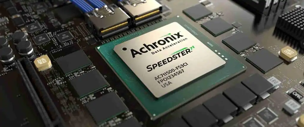
This article compares two popular FPGA families from AchronixSemiconductor – the Speedster7t and the newer Speedster22i HD. We will explore the architecture, capabilities, and applications of these FPGAs to understand how they differ and which works best for your requirements.
Overview of Achronix Speedster FPGAs
Achronix Semiconductor is a pioneering company focused on high-performance FPGAs for advanced computing markets. Their Speedster FPGA family is optimized for data acceleration applications with very high throughput and bandwidth needs.
Some key aspects of Achronix FPGAs:
Utilize a 2D network-on-chip (NoC) architecture
Have high-density and high-speed SerDes interfaces
Include hard PCIe blocks, DDR memory controllers
Feature high-bandwidth GDDR6 memory interfaces
Offer dedicated AI engines and ML processors
Provide leading-edge process nodes down to 7nm
The Speedster7t and Speedster22i HD represent two generations of Achronix FPGAs aimed at high-end applications.
As a 16nm FinFET product, the Speedster7t series focuses on providing a balanced set of features including high density, SerDes interfaces, and built-in AI acceleration at an optimal power envelope.
Achronix Speedster22i HD FPGA
The Speedster22i HD is the latest generation from Achronix built using the advanced 7nm process node. It pushes the performance and density envelope further. Key features:
The Speedster22i HDT leverages the 7nm node to significantly boost logic capacity, bandwidth, AI performance and DSP capabilities for cutting-edge applications. The higher power envelope allows leveraging the density and speeds.
Head-to-Head Comparison
Here is a direct side-by-side comparison of the major specifications and capabilities of the two FPGAs:
Parameter
Speedster7t FPGA
Speedster22i HDT FPGA
Process
16nm FinFET
7nm FinFET
Logic Cells
Up to 1.5 M
Up to 4.5 M
Embedded RAM
Up to 68 Mb
Up to 576 Mb
External Memory
2GB GDDR6
8GB GDDR6
DSP Slices
25,200
132,000
AI Engines
4-16 INT8 cores
Up to 128 INT8 cores
AI Performance
33 TMACs
1 PetaMACs
SerDes
16-36 @ 32Gb/s
64 @ 32Gb/s
Ethernet Ports
36x 400GbE
112x 400GbE
Transceivers
48 – 400GbE
112 – 400GbE
Typical Power
< 75W
Up to 300W
Key Differences
Based on the above comparison, we can summarize the main differences between the two FPGAs:
Density – The Speedster22i HDT offers 3X higher logic capacity and 8X more embedded memory compared to the Speedster7t.
Performance – The 7nm Speedster22i provides over 30X higher AI performance with up to 128 INT8 AIE cores vs just 16 cores in Speedster7t.
Memory – Speedster22i has 8GB of cutting-edge GDDR6 memory compared to 2GB in previous generation.
Interfaces – Speedster22i doubles the number of 32Gb/s SerDes lanes and triples the 400GbE transceiver count.
Bandwidth – With over 3X more DSP slices and higher memory bandwidth, Speedster22i enables much higher overall system bandwidth.
Power – The Speedster22i lacks power efficiency with up to 300W envelope, 4X more than the Speedster7t.
Cost – Being a newer high-end 7nm product, the Speedster22i lineup carries a higher cost over the older 16nm Speedster7t.
Based on their capabilities, here are some ideal use cases for the FPGAs:
Achronix Speedster7t – Mainstream data center accelerators, network cards, industrial automation, defense systems, testing/prototyping of FPGA designs.
Achronix Speedster22i – Advanced AI acceleration, machine learning training, high-frequency trading, genome sequencing, aerospace computing, high-end networking, military systems.
The Speedster22i HDT is better suited for cutting-edge applications needing maximum performance and bandwidth in sectors like AI, cloud computing, networking, and high-end computing. The Speedster7t provides a more optimized solution for cost-sensitive or mid-range applications across defense, automation, 5G systems.
Conclusion
The Achronix Speedster22i HD FPGA offers significantly higher density, performance, bandwidth, and memory compared to the previous generation Speedster7t FPGAs. The 7nm process allows packing in more logic, memory, DSP blocks, and AI engines into the Speedster22i while improving energy efficiency. It represents the bleeding-edge of capabilities for accelerating challenging workloads like AI-inference.
On the other hand, the Speedster7t still powers a wide range of mainstream applications with its proven architecture. For systems with tighter power budgets or lower compute needs, the Speedster7t likely represents the cost-optimized option. Understanding these key differences allows selecting the right Achronix Speedster FPGA for your specific application and performance requirements.
Frequently Asked Questions
What process nodes are used to manufacture these FPGAs?
The Speedster7t uses a 16nm FinFET process while the Speedster22i leverages a more advanced 7nm FinFET node to provide a significant density and performance boost.
How do the embedded RAM and external memory resources compare?
The Speedster22i HD has almost 10X more embedded RAM at 576Mb vs 68Mb in Speedster7t. It also offers 8GB of cutting-edge GDDR6 external memory compared to just 2GB GDDR6 in the previous FPGA.
What machine learning capabilities are included in the FPGAs?
Both FPGAs contain dedicated AI Engines (AIE) for accelerating neural network inferencing workloads. The Speedster22i integrates up to 128 INT8 AIE cores delivering up to 1 PetaMACs of AI performance – over 30X more than the Speedster7t.
How many high-speed SerDes lanes are available in each of the FPGAs?
The Speedster7t offers between 16-36 lanes of 32Gbps SerDes while the Speedster22i doubles this number to 64 lanes of 32Gbps SerDes. This provides much higher aggregate bandwidth.
What is the maximum power consumption for the two FPGAs?
The Speedster7t typically consumes less than 75W making it suitable for mainstream and low power applications. In comparison, the Speedster22i can consume up to 300W to deliver maximum performance, so it is targeted at data center and HPC type workloads.
Measuring the pH value of liquids is important for many applications such as checking water quality, monitoring chemical processes, agriculture, food processing, and more. pH sensors allow you to precisely measure the acidity or alkalinity levels of a solution. These sensors can be easily interfaced with Arduino boards to create DIY pH meters or data loggers. This comprehensive guide will teach you all about pH sensors and how to connect them to Arduino for taking pH measurements.
What is pH and Why Measure it?
pH stands for ‘potential hydrogen’ and is a measure of the hydrogen ion concentration in a solution. It indicates how acidic or basic a liquid is on a scale from 0 to 14. Pure water has a neutral pH of 7. Acidic solutions have a lower pH while bases have a higher pH.
pH sensors work by measuring the electron activity in a solution and generating a voltage proportional to the pH. This voltage signal can then be conditioned, amplified, and converted to a digital value for processing by a microcontroller.
The sensing part of a pH probe consists of a glass electrode and a reference electrode. The glass electrode develops an electrical potential proportional to the hydrogen ion activity as given by the Nernst equation. This potential is measured against the stable potential of the reference electrode.
Common types of pH sensors include:
Glass electrode sensors
ISFET (Ion Selective Field Effect Transistor) based sensors
Antimony electrode sensors
Out of these, glass electrode pH sensors are the most popular and commonly used with Arduino.
Parts Required
To interface a pH sensor with Arduino, you will need the following components:
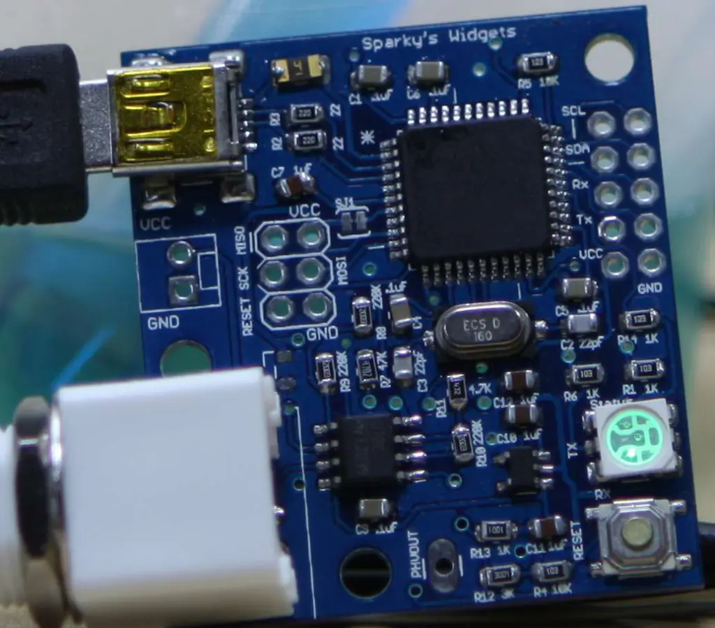
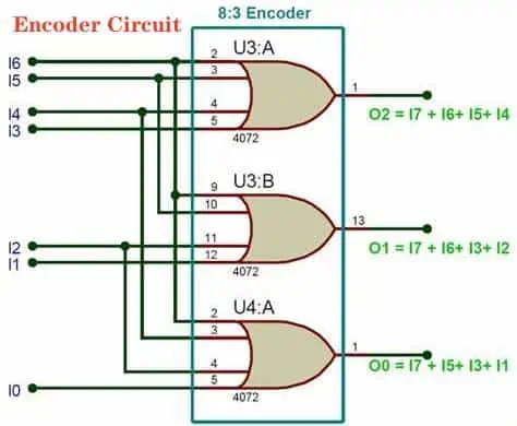
The basic circuit diagram for connecting a pH sensor to Arduino is shown below:
The pH probe generates a very small voltage (in mV range) proportional to the hydrogen ion concentration. This needs to be amplified to scale it to the 0-5V range of the Arduino analog inputs.
An op-amp IC like LM358 can provide the necessary amplification or buffering. The 10k resistor helps set the gain to about 200X to amplify the 0-1000mV sensor range to 0-5V DC range for the Arduino.
The Arduino can then read this amplified pH voltage on one of its analog input pins to measure the pH of the solution.
Connecting the Hardware
Follow these steps to connect the pH sensor hardware with Arduino:
Connect the pH probe to the BNC to Banana plug adapter.
Connect the adapter ground (-) jack to the Arduino GND pin.
Connect the adapter signal (+) jack to the non-inverting input of the op-amp IC.
Install a 10kΩ resistor between the op-amp output and inverting input. This sets the gain for amplification.
Wire the op-amp output to an analog input pin on the Arduino such as A0.
Power the op-amp IC if needed by connecting the power and ground pins to 5V and GND respectively.
Optionally, you can add an LCD display, SD module, etc to the available Arduino pins.
Insert the pH probe in the solution to be tested.
This completes the sensor interfacing circuitry. Make sure all connections are secure before powering up the Arduino board.
Calibrating the Sensor
Before taking pH measurements, the sensor needs to be properly calibrated. Calibration eliminates any inherent offsets in the probe and sets the measurement scale accurately.
Calibration involves immersing the sensor in calibration solutions of known pH like 4.0, 7.0 and 10.0 and adjusting the voltages/readings accordingly.
Here are the steps to calibrate the pH sensor:
Allow the sensor to stabilize in a pH 7.0 solution for 30 minutes.
Take a voltage reading with the sensor immersed in the pH 7.0 buffer and note it down.
Rinse the probe with clean water and place it in the pH 4.0 calibration solution.
Measure and note down the sensor voltage at pH 4 after it stabilizes.
Repeat the same process with the pH 10 calibration solution.
Use these 3 points to create a calibration curve for converting voltage to pH values.
The Arduino sketch can use this function to return accurate pH readings.
Periodically recalibrate the sensor every few weeks for best accuracy.
Arduino Sketch
The Arduino software needs to read the analog voltage, map it to a pH value based on the calibration curve, and display/log the results.
Here is a sample Arduino sketch to do this:
//pH Sensor Arduino Code const int phPin = A0; //pH sensor connected to analog pin A0 float phValue; //to hold pH value void setup() { Serial.begin(9600); //calibrate pH meter function calibrateSensor(); } void loop() { phValue = readpH(); //read pH value Serial.print("pH: "); Serial.println(phValue); delay(1000); } //Function to calibrate sensor void calibrateSensor() { //calibration codes//store calibration points//map voltages to pH values } //Function to read pH float readpH(){ //read analog voltage//map voltage to pH based on calibration return ph; //return pH value }
Modify the calibration logic and reference voltage to pH mapping based on your specific sensor calibration. This will give you accurate real-time pH measurements that can be displayed or datalogged.
Displaying the Output
To display the pH value on an LCD module, simply print the phValue to the LCD in the loop() function:
This will continuously log the pH measurements to the SD card for later analysis.
Applications and Examples
The Arduino based pH sensor setup can be utilized for:
Aquarium or swimming pool pH monitoring
Checking water quality and alkalinity
Hydroponics monitoring
Measuring pH of juices, drinks
Environmental water analysis
Science experiments and projects
By using specialty pH probes, the sensor can also measure pH in non-aqueous solutions like fats, oils, solvents etc.
Conclusion
Measuring pH is important for a wide range of chemical processes and applications. By interfacing a pH electrode probe to an Arduino through a suitable amplification circuit, you can build your own DIY pH meter. With proper calibration, these Arduino pH sensors can provide reasonably accurate pH measurements for your needs. The pH data can also be displayed, charted, or datalogged using Arduino. Overall, Arduino provides a simple yet powerful way to incorporate pH testing ability into your projects.
Frequently Asked Questions
What is the typical output range of a pH sensor?
Most pH sensors have an output voltage range of around -400mV to 400mV or -1500mV to 1500mV corresponding to the 0-14 pH scale. This small mV range voltage needs to be amplified to the 0-5V range for Arduino analog inputs.
Do I need a special pH probe for Arduino?
No, you can use any standard laboratory pH probe with BNC connector. Just get a BNC to banana plug adapter to match its pins to the breadboard. There are also special waterproof Arduino compatible pH probes available.
What solutions are used for calibrating a pH meter?
Calibration is done using standard buffer solutions like ph 4, ph 7 and ph 10. Precision buffer solutions that provide exact ph values for calibration are also available. Choose calibration buffers close to your expected measurement range.
Can I interface other chemical sensors to Arduino?
Yes, Arduino can interface to many types of electrochemical sensors apart from pH, including CO2, dissolved oxygen, nitrogen, and more. Similar circuits with amplifiers and calibration are needed to adapt their signals for Arduino.
How often should the pH meter be calibrated?
pH sensors need to be recalibrated every 1-2 weeks to maintain accuracy. Frequent calibration compensates for ageing effects of the glass electrode membrane over time. Calibrate more often for very precise measurements.
How to build an Arduino PH sensor
We all know PH is an essential thing for drinking water. If you don’t take care of this crucial ingredient, you might ruin your entire meal in a matter of seconds. This article will teach you how to build an Arduino Ph sensor as a beginner project for someone who doesn’t know what they’re doing.
What is an Arduino?
We can regard an Arduino as a ‘microcontroller.’ This means that it is a tiny computer that you can use for electronic projects (and for much more). It can act as the main component in a huge amount of projects. By combining multiple projects, you can make something even greater.
We do this project using the Arduino Uno and the Arduino 1.0.2 IDE (integrated development environment).
These are the components we will be using:
– Arduino Uno ($30)
– Arduino Starter Kit ($80)
– Ph probe ($50)
Before you get started, make sure you set up the Arduino kit by following the instructions that came with it. This takes approximately 1 hour and 30 minutes to do. However, if you’re in a hurry, it’s possible to do this in 20 minutes by following this tutorial.
pH is a measure of the acidity or alkalinity of an aqueous solution.
The pH scale is logarithmic, and it measures the negative base ten logarithms of the activity of hydrogen ions in a solution.
The pH scale is from 0 to 14, with seven being neutral, less than seven acidic, and greater than seven is alkaline.
Every solution has a pH that a simple electrode can measure. For example, lemon juice has a pH of 2-3, and vinegar has a pH range from 4-6. Clean water may have a pH between 6.5 and 8, depending on the area you live.
A downside to this value is that it’s not used for precise recipes when cooking.
A pH level of 7 is considered neutral, any lower and it becomes increasingly acidic, any higher and it becomes progressively alkaline.
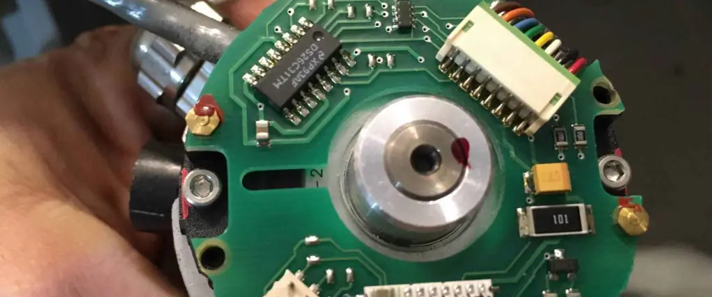
A probe
A probe is an electronic device that allows you to measure the amount of voltage or current flowing through a circuit. For example, we will be using a Ph probe when measuring PH. This sensor lets us know if the water contains acids or bases.
The PH probe has two wires: one red and one black. The blue wire connects to 5V, and the black wire connects to the Ground(GND). The Red wire is what you use to measure the PH. It’s a very sensitive probe that can measure the pH value. You connect it to the Arduino, and in a concise period, it will tell you if the solution has an acidic or basic value.
pH Sensor for Arduino
There are many different models of Ph Sensor for Arduino. Unfortunately, many of them appear similar. But, if you want to do a good job and make sure your sensor will last for a long time, you should go with one from Rayming PCB & Assembly and get this one.
You can connect the sensor to the Arduino board using two wires. Once the connection is complete, you can start testing the sensor. You should do this by using a small piece of bread. The amount of sugar in bread is close to human skin, so it is easy to see how the sensor will react.
One can adjust the Ph probe to any other values as well. You need to tell it which value you want, and it will give it back to you (the value). You can do this by using a simple piece of bread.
Testing the sensor after connecting it to the Arduino is essential before using other solutions. You should always let the sensor rest for around 24 hours to stabilize and work properly. You will have to do this again when you connect it to a new circuit later.
The Ph probe requires between 3.5V and 5V to read the solution’s pH value properly. Therefore, to monitor the pH level of your Arduino project, you will need to use a voltage regulator or a voltage divider.
This project will use two transistors and two resistors to get the proper readings from different circuits or sensors. For example, if you want to measure the temperature on your Arduino board, you can get that information with a thermistor. However, the readings for both temperatures and pH depend on the circuit’s current level and, therefore, on the value used in your soil ph sensor Arduino.
Components and supplies
To build this little project, you will need to gather a few components and supplies. Here is the list:
Before you start building your sensor, make sure to read these instructions carefully. Your project will not be waterproof. Ensure that you place the device on a flat, safe surface.
When moving or storing your Arduino circuit, always unplug the sensor from the Arduino to make sure it doesn’t short-circuit on something.
If you are unsure about this project, don’t hesitate to ask someone about electronics and programming. You will learn more, and your project and knowledge will grow bigger.
Other than that, almost everything is as simple as a ‘Plug and Play’ installation. If anything fails to work correctly, try restarting the Arduino IDE. If it still doesn’t work, check all the connections again to ensure there aren’t any loose wires touching other components or parts of the circuit.
Step 1: Prepare the housing
You can choose to make the Arduino board a stand-alone device so that you don’t need an enclosure. But, we think it’s better to use an enclosure because it gives you a safer way to store your sensor or Arduino board in the future. But, of course, you could also use the box that comes with your Arduino kit.
First, you will have to cut out two holes for the LCD module, the mobile phone camera, and the micro SD card slot.
You should place the LCD on the bottom of the enclosure. Make sure you leave enough room for the mobile phone camera and micro SD card slot.
Supply a hole at the right size for the LCD screen, and make a hole on the back of your enclosure so that you can place a screw to fix it in place.
Place your finished product on top of another piece of acrylic sheet or plexiglass that is slightly larger than your enclosure. Then, cut it to the same size as a saw. Once you finish both pieces, drill two holes for the mobile phone camera and one for the micro SD card slot.
Don’t worry if you mess up while making these holes. You can always take your enclosure apart and fix all these problems. Do this by using a drill bit that is slightly smaller than your cord and then cut all of these holes with a rotary tool, or you can use a saw if you want to make smoother cuts.
Step 2: Install electronics in the housing
Install three components, two transistors, and one resistor for the Arduino pH sensor. Here is a quick explanation of these components:
1) First, we will install the 220-ohm resistor from the LCD module side so that you can use an external power source. You also want to connect this to your Arduino board’s positive (red) side.
2) Next, connect the LCD module’s ground to the Arduino board’s ground.
3) To install the two transistors, you will use a breadboard. First, make sure that you place the transistor in each circuit correctly.
4) You will also have to add an extra ground wire between the transistors and the breadboard since they don’t share a common ground with the Arduino board. Finally, connect the transistor and resistor to GND on the Arduino board.
5) You can now install the Ph probe by using jumper wires.
The Ph probe should be installed like the picture above to connect the wires to your Arduino board. The GND wire should be connected to one of the Arduino’s pins and should go in between both transistors to be grounded.
You can wire the other wire (from the Ph probe) directly with one of the transistors (the transistor without an extra ground wire).
Finally, you can install the LCD module using two wires. You need to connect one pin to the Arduino board and the other to the transistor that shares a ground with the Arduino. You can use a breadboard for this if you want, but it is much easier just by connecting both circuits directly.
Step 3: Wire the electronics together
You have already installed all the components in your housing, and now you have to connect them. For this step, make sure you follow the circuit diagram I created for this project. This diagram will find details about every component’s location and where you should connect it to.
Just connect the parts that are highlighted in green using jumper wires. You can bend the wires to make them fit in between the housing and your Arduino board without causing any harm to them or their circuit.
Now you should be able to plug and play! Feel free to try out all of your sensors’ different settings and see how it works.
Once you have your Arduino pH circuit assembled, you can now place your sensor in a safe environment to see how well it works. However, you don’t want to put it in the water yet because you haven’t installed the software to let your sensor know its pH level.
You can control the water temperature by sliding the potentiometer while controlling the voltage by holding down the “set” button.
Step 5: Load the code Onto Arduino UNO
You can download the Arduino code for the project from here. It’s a sketch that you can use to control your sensor.
You will have to install and run the Arduino IDE on your computer. You will also have it on your mobile phone for setting up, uploading, and testing sensors in the future.
Once you have finished installing everything, open up your Arduino IDE on your computer, select ‘File/Open and select the code you downloaded from our page.
The code contains the description of each sensor on the Arduino board, and you can easily change it to suit your needs.
Now connect your Arduino UNO to your computer with a USB cord and then click on ‘File/Upload’ this will send the code to your sensor so that you can start testing it out.
Click ‘Tools/serial monitor’ This will open up a terminal in which you can test your sensor! Type “M50” in the terminal to heat the water at 50 degrees Celsius.
After that, check out the display, and you will notice that the LCD screen is currently on, and it says: “Temp 1.0” on top of it.
If you type “M10” in your terminal, you will notice that the temperature is now 10 degrees Celsius hotter, and the LCD screen will now say “Temp 2.0”.
Then type “M20” to see that the temperature has risen to 20 degrees Celsius.
Finally, we can test our pH sensor and see how well this sensor works! Type “pH” in the terminal, and the LCD screen will say “2.0”.
That’s how you can use this Arduino pH sensor to monitor the levels of your environment.
Step 6: Calibrate the sensor
You can calibrate this sensor so that it will be able to tell the exact pH level that is in your environment. For this part, you will need two common solutions in a range of 1-14 pH. In this case, we used a solution at five and another at 10.
Our solution at five pH was pink, and our solution at ten pH was purple. So we mixed these two solutions, and our sensor read “7”. Which means you calibrated the sensor at 7.
You can do this step multiple times to see how well your sensor calibrates and reads the pH level in your environment.
Step 7: Use your DIY pH sensor With Arduino!
After calibrating the sensor, you can use it with Arduino electronics. Here is a code snippet that you can use to see how well your sensor works:
This code will turn on (red LED on) the LED connected to your LED strip (VCC) and display “Temp” on the LCD screen. You can change these values in the sketch to suit your needs!
Now again, open up your Arduino IDE and upload this sketch onto your Arduino board.
This will allow your pH sensor to bridge your sensors and Arduino board. With this, you can control many different sensors from one device!
Now take this same code, but change the text and change it so that it says “pH” instead of “Temp.”
Then connect your pH source (a five pH) to your Arduino board. Then download a sketch from here. This will let your Arduino board be able to read your pH sensor!
Notice that when you download and upload the program, the LED light will turn blue and red when it recognizes that the sensor and Arduino need a connection.
Now type “pH” into your terminal, and you should see this screen:
That’s how easy it is to use this DIY pH sensor from Arduino electronics. You can now use it as a simple probe for your other sensors in our project.
Testing Arduino pH Tester
It is essential to test the pH sensor in different environments to ensure that it will perform well. In this part, I will show you how we tested out the pH sensor in a few different environments. This would allow you to know that the sensor is doing what it is supposed to do.
Here’s how we tested it out:
Testing pH sensor in the air
We tested the pH sensor in an open environment. First, we used a clear jar and filled it up with distilled water so that there was no conductivity of the water, and we stirred for about 30 seconds. Next, we put a piece of pH paper on top of the solution and connected an Arduino board using a USB cable.
Then, we took the sensor apart and connected it to our lab equipment. We tested the voltage output from the sensor, compared it to a known value, and found that there was about 0.1 volts difference between both of them. We then compared the results to the pH table online and found that the readings were correct!
Testing pH sensor in hard water
We used distilled water again to have no water conductivity in the jar. Next, we used a hard water solution and poured it into the jar. We then put some pH paper on top of the water and connected the other end to our Arduino board. Then we took our pH sensor apart, stripped off its casing, and put it into the hard water solution. From there, we tested both outputs from the Arduino and lab equipment.
To our surprise, both of them were about 0.02-volt difference which is acceptable for our sensor since it is an analog voltage output device. Unfortunately, we tested one previous version of the pH sensor in hard water, and it didn’t give us a reliable result, so we needed to replace it with this one since it is more precise.
Testing pH sensor in saltwater
We used the same setup again, but we used a saltwater solution, about 0.4 volts difference from our analog output device. Both outputs were still within an acceptable range, and we tested both of them using a previous version of the pH sensor in saltwater, and it also gave us similar results.
There are a few common errors that we can find when building this Arduino pH sensor from scratch. Here are some of them:
java.lang.StackOverflowError
This error happens when the code you are trying to upload doesn’t work properly. This might be because you did not implement some of your library’s functions in your sketch. To fix this problem, comment out unnecessary codes and compile and upload again.
Sketch Too Large for FLASH Memory
If your sketch is too large for the flash memory, you might get this error message, which means your sketch is too big to fit in the flash memory. To fix this problem, comment out unnecessary codes and compile and upload again. If it still doesn’t work, you can use another Arduino IDE instead of using the default one that comes with Arduino boards.
Unsatisfied Link Error
When you compile your code and upload it on your Arduino board, you might get the “Unsatisfied Link Error” message box. This means that there is a library that you need to add to the Arduino IDE before trying to compile and upload again. But, of course, you can always go to this page and download this library into your Arduino IDE to use it in your project.
Sketch Uploads Successfully, but Nothing Happens on Board
This error happens when you try to upload a sketch, but nothing happens on your board. This might be because there is something wrong with the code you are trying to upload. First, try removing all the comments from your file and then re-compile it again. If that doesn’t work, you could use this other Arduino board instead.
Serial Port Already in Use
When you upload sketches onto your Arduino board, you might get a message box telling you that “Serial port is already in use.” This might be because your IDE tried to upload on a serial port and failed because it was not connected. To fix this, try to restart your Arduino IDE by closing it and re-open the IDE.
Launch4j Error
Sometimes, when you compile your code, a Java error comes up and tells you that the Launch4j cannot run. This is because your Arduino board is not detected by your computer since there might be a problem with the serial connection between your computer and the Arduino board. Connect your Arduino board with a new USB cable to fix this problem.
Invalid Device Signature Error
This error happens when you try to connect an Arduino board to your computer, but your Arduino board doesn’t appear in the list of recognized devices. To fix this, remove the IDE, and after you reboot your computer and then re-plug it into the USB port, this should help.
The code doesn’t start on Power Reset
Sometimes, the code you put into your Arduino IDE doesn’t work when you compile it. This might be because you need to put in the PIN before starting. To fix this problem, comment out the “Serial. begin()” line by putting a “#” at the beginning of that line and then upload the program onto your board again.
Board not in sync
Your board may be out of sync with the Arduino IDE. If you can’t upload any sketch onto your board, try resetting and restarting it by disconnecting the power and reconnecting it to a new USB cable. This should sync it up to Arduino IDE to upload sketches onto your board.
Arduino Board not Recognized
This might be because your Arduino board is not compatible with this type of hardware. If you have an Arduino Uno that you cannot use, you might consider finding a different one.
Conclusion
Finally, we have finished our first pH sensor Arduino project. We started by looking at the basic parts that we will need for this project: an Arduino Uno and a pH sensor. After reading about how these sensors work, we decided to use the DS18B20, easy to find and cheap. Fortunately, most of the parts we used were available on Amazon, so there was no need to look everywhere to get what we needed.
After building our pH sensor, we tested both possible scenarios using hard and saltwater. We found that both outputs were still within an acceptable range from the common range of pH values. Both values were around seven and below eight, which means our sensor gave us a correct output.
Finally, we learned about some common errors and how to fix them for your Arduino project.
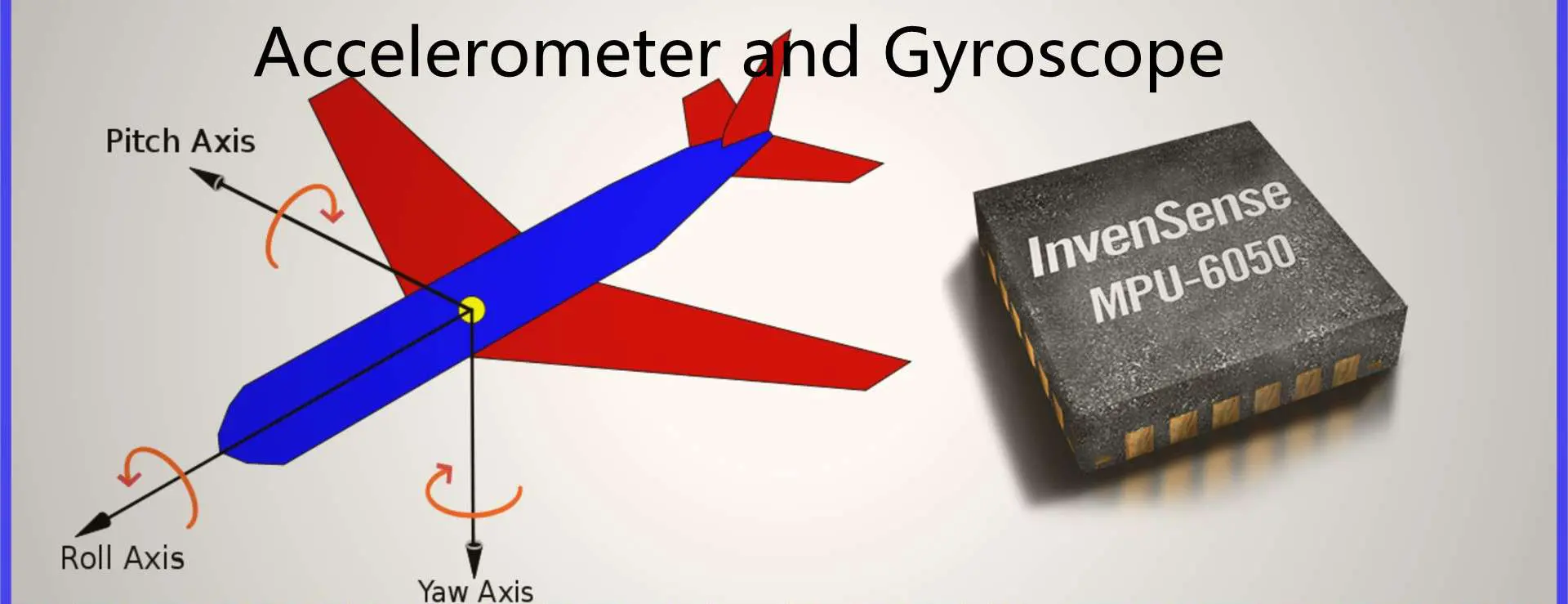
Consumer electronics are growing faster each year. As a result, people have become more aware of how technology can assist them. One popular device that has been on the rise is an accelerometer and gyroscope. Microelectromechanical systems (MEMS) are becoming the critical element of these devices. They give the user a new way to interface with their device. They also detect the device’s motion and interact with it in new ways.
These devices are helpful for the consumer and industrial markets. They include the automotive and aerospace industries. Here, MEMS can sense motion in automobiles, ships, and aircraft. We can also use these sensors to sense speed and directions. It will increase the overall efficiency of these products. MEMS are helpful in airbag control units, side-impact airbags, and seat occupancy detectors. We also use them in smart cruise controllers in the automotive industry. An accelerometer and gyroscope are also beneficial in video game consoles. It is an example of consumer electronics. A microchip processes the information provided by this device before sending it to the console or a gaming platform.
What is an Accelerometer?
An accelerometer is a device used to detect the acceleration of a free-falling object. It consists of a mass, spring, and linkage. They suspended the mass from the linkage that one can replace from its rest position. If the object is accelerating vertically, the suspended mass will move opposite. The displacement of this mass measures how much acceleration the object is undergoing.
The accelerometer functions by detecting the acceleration of an object. We can use an accelerometer in many different applications. It is usually used by nature because some organisms use it to detect gravity or the earth’s gravity. Some scientific institutions use them to measure rotation rates and cosmic acceleration. Some forces cause these devices to work. They include Gyroscopes, Inertial Vector Indicators (IVI), MEMS, and Magnetometers.
An object is free-falling, and it is descending due to gravity. After a certain time, the object will reach a certain speed (this depends on the object’s weight). The acceleration due to gravity will be equal to g. A physical force then acts on the mass, causing it to decelerate. An accelerometer observes the deceleration. It measures the change of momentum caused by this force—this force changes when an accelerating force acts on it.
Piezoelectric effect:
An accelerometer also works with the effect of the piezoelectric effect. A crystal with bound atoms will create an electrical charge when you compress it. If you compress it, it will generate a voltage. The connection of this device will then cause it to work as an accelerometer.
Magneto-resistive effect:
An accelerometer is also composed of a magneto-resistive effect. It senses a small magnetic field. So, it detects the acceleration caused by magnetic forces.
Change in Capacitance:
In specific applications, an accelerometer works by measuring changes in capacitance. Thus experiencing a change in capacitance when it is free-falling. 2 capacitive plates are present. A coil and a capacitor connect them. The device observes the change in capacitance. We can use it to determine that an object is falling.
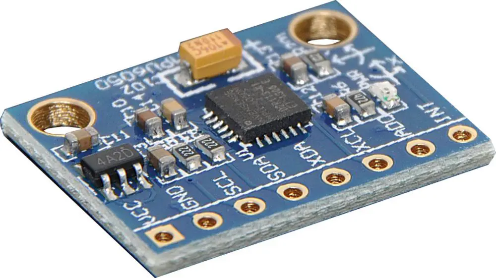
MEMS Accelerometers
Accelerometers depend on other operating principles. We use them in consumer electronics, automotive, and aerospace industries.
The accelerometer is one of the most popular MEMS devices. We can use it to detect vibration, shock, and small changes in the direction of an object. It is also a very efficient device since it requires little power when used. Therefore, you can leave it on for a long without draining the device’s batteries.
Microelectromechanical systems (MEMS) are the key element of accelerometers. They measure acceleration, rotation, and vibration. We measure the acceleration by the change in position of a proof mass. The proof mass is along with a resonant structure.
The most widely used type of accelerometer is the capacitive electromechanical sensor. Therefore, we also refer to it as an accelerometer.
Accelerometers are usually composed of a sensor chip and an integrated circuit. It has capacitors, inductors, and resonators (tuned circuits with resonant frequencies).
The sensor chip can be traditional CMOS, silicon-based CMOS technology, or other processes.
The device uses the effects of the piezoelectric effect to measure acceleration. The device observes the change in capacitance.
Applications of Accelerometers
We use accelerometers in a variety of applications, including:
1. Compass/Map applications:
In GPS navigation systems, Rayming PCB & Assembly use accelerometers to detect if the device is in motion. It will also detect which direction it is moving in. Through axis-based sensing, phones and tablets can determine their orientation and direction.
2. Tilt sensing:
Using a gyroscope, we can use an accelerometer to detect a device’s orientation. For example, iPhone uses an accelerometer and gyroscope. First, it detects when the user rotates the phone from portrait to landscape mode. Then, it changes applications accordingly.
3. Earthquake detection:
We use accelerometers to detect an earthquake. It also determines the magnitude of its movement.
4. Fall sensing:
We use accelerometers in advanced personal protection systems. They detect a fall and trigger life-saving technologies, for example, airbags and seat belts.
5. Medical devices:
We use accelerometers to detect a momentary speed of blood circulation. It also delivers critical information about the status of a patient. Artificial body parts, such as heart valves and hips, also have accelerometers. They help detect movement around the prosthesis.
6. Fitness trackers/wearables:
Accelerometers detect physical activity. This can detect if the user is walking, running, or biking.
7. Games and applications:
We use accelerometers to detect subtle movements during a game—for instance, the response time of a joystick controller.
8. In-car applications:
Accelerometers detect if the driver loses control of the vehicle. It then triggers an appropriate safety response.
What is a Gyroscope?
A gyroscope is a device that uses its natural inertia to measure the rate of rotation of an object. We consider it a mechanical effect. We use gyroscopes in geophysics space research and various electronics applications.
How it works
A gyroscope consists of two main parts:
A pair of weighted rings called gyroscopes
An angular rate sensor (usually called a magnetometer), which we do not use.
It works through the precession effect when a gyroscope rotates around one of its axes. It cannot detect the rotation angle when it is in an equilibrium position. But after its rotation, it will point up to the axis on which you placed it.
In this case, an inertial force acts upon the gyroscope. Since the angular momentum remains constant, extra kinetic energy will go with this motion. This force will make the gyroscope go backward. However, since nothing happens to the gyroscope, we call this the precession. Another precession effect is that a gyroscope will resist any change in its angular momentum until you apply torque.
The rotation rate of an inertial frame can measure the rate at which an object rotates in an accelerating frame. It does this through Einstein’s equivalence principle or Newton’s first law of motion.
Applications
We mainly use gyroscopes for navigation, flight control, and navigation in space exploration. However, they are also helpful for medical devices. An example is heart monitors and other medical equipment. Nuclear magnetic resonance (NMR) spectrometers also use gyroscopes to detect movement.
MEMS Gyroscope
The MEMS Gyroscope is also known as a Microelectronics-Mechanical System (MEMS) gyroscope. We use the MEMS engine in smartphones and cameras.
We use Gyroscopes in smartphones to enable image stabilization. It helps capture clear images while recording videos.
We also use it in drones that use MEMS technology. Even when the drone is not under direct human control, they enable flight control.
MEMS Gyroscopes are small miniaturized sensors. They use silicon chips, MEMS, and advanced processing technologies to achieve high precision. We use them in various applications, including gyroscopes, cameras, and navigation systems.
Applications of Gyroscope
In the past, we used MEMS gyroscopes in missions navigation systems. However, the application is expanding. Some of the notable ones include:
1. Consumer electronics through MEMS gyroscopes:
The demand for MEMS is rising in consumer electronics, particularly smartphones and tablets.
This is because most smartphones and tablets today come with a 3-axis gyroscope.
Gyroscopes can detect if a device is moving too much. For example, it would trigger an airbag system in an accident. If it detects a hard fall on the ground, it will call emergency responders using GPS.
2. Inertial guidance systems
Inertial guidance systems are essential in missiles, rockets, spacecraft, and UAVs.
The inertial guidance system can determine position and orientation in space.
3. Airplanes through MEMS gyroscopes:
A 3-axis MEMS module serves as an essential component. It enables the roll axis of a fly-by-wire (FBW) flight control system. This technology makes flying a jet at supersonic speeds possible for pilots.
4. Stability in vehicles, motorcycles, ships:
MEMS gyroscopes can determine the vehicle’s lateral and longitudinal stability characteristics. We can use it to assess the condition of the vehicle’s chassis. We also use stability in automobiles. For example, it determines if the car loses balance or is unstable while traveling on a curvy road.
5. Space stations:
MEMS gyroscopes and accelerometers help determine the space station’s orientation, speed, and direction.
Accelerometers help in motion capture systems, game controllers, and Kinect. They all can measure changes in motion. We do this by the accelerometer measuring the changes in acceleration caused by forces applied on a device.
Accelerometers can measure acceleration caused by gravity, which we can also use to detect gravity. The accelerometer can also measure static forces like downwards force or upwards force. But it cannot detect dynamic forces like movement and movement over time. So to find a good one, you need to consider the following:
1. Range:
Accelerometers can measure acceleration up to 5000 Gs. So if you want to measure accelerations with high precision, it is better to go with the accelerometer with a high range. They include an accelerometer with a range of 2 Gs or above.
2. Interface:
We can connect accelerometers through digital or analog. But to get the best performance, it is better to go with the accelerometer that uses a digital interface.
3. Sensitivity:
The sensitivity of an accelerometer is the amount of vertical force it can measure per the change in acceleration. Unfortunately, it is also associated with low sensitivity. So you will not measure it accurately if you are accelerating at a constant rate.
4. Axes:
There are two types of accelerometers, namely two or three axes.
The most common type of accelerometer that is in use today is the one that has only one axis. It looks like a mini 3-axis accelerometer. If you want to measure acceleration with high precision, you should go for the miniaturized 3-axis accelerometer. However, this type of accelerometer can be available on only a few devices. They are challenging to manufacture.
5. Power:
The mass of the device and the size of the circuit board will affect its performance sensitivity and power consumption. So before you go for any accelerometer, you must consider these factors.
6. Usage:
It is also essential to understand how to use the accelerometer in the device.
7. Cost:
Before deciding on an accelerometer to use in your project, you must also consider the cost. You should know that you can use Richter or tilt switches instead of accelerometers. This is when you want to measure acceleration on a small budget.
Types of Accelerometer
a. Grove – 3-Axis Digital Accelerometer ±16g Ultra-low Power (BMA400)
This is a product of the BMA400 sensor from Analog Devices. The Grove -3-Axis Accelerometer BMA400 is an ultra-low-powered digital accelerometer. We use it in robotics and medical devices.
b. ADXL 3-Axis Accelerometers series
There are three different series of accelerometers based on BMA200.
The ADXL3-03 is a low-power, high-performance 3-axis analog accelerometer. It is available in 1G and 4G options.
Most people believe the ADXL3 -05 is the most accurate class at ±5 µg. In addition, it provides increment and decrement detections. It has a resolution of ±2 µg per step throughout the full operating range.
How to choose a Gyroscope
Gyroscopes help in devices such as vehicles, cameras, and drones. We use them to help improve a device’s stability and measure speed.
Gyroscopes help reduce rollover accidents and provide more accurate speed readings.
You must choose your gyroscope wisely because not everyone has the same requirements. So there is no one size fits all gyroscope. This makes it even more difficult for you if you have no prior background knowledge about them.
These are the factors to consider when choosing a suitable gyroscope:
Range:
Gyroscopes can measure angular velocity up to 2000 degrees per second. So you need to choose one with a high range, such as a gyroscope with a range of 2000 degrees per second or above.
Range affects the amount of information you can get from the gyroscope. So you should choose one which has the highest range possible for your project.
Digital vs. Analog:
Digital gyroscopes are more expensive than analog ones. But they are easier to interface with and provide more accurate results. So to get good performance, you should choose an analog gyroscope over a digital one.
Conversion Ratio:
The conversion ratio of an analog gyroscope refers to the accuracy of the speed measured in degrees per second. An accurate speed measure is much preferable to an inaccurate one. So choose a gyroscope that has the highest possible conversion ratio. The parameters that govern the accuracy of a gyroscope are range, convert rate and temperature coefficient. So you will have to consider them when choosing one for your project.
Number of Axes:
Two gyroscopes are single and dual axes. A single-axis gyroscope is suitable for measuring angular velocity around a single axis. We can use it for applications such as stabilization. On the other hand, a dual-axis gyroscope is essential in navigation or flight control. So choosing a dual-axis one over the single-axis type is better.
Power:
Gyroscopes consume a lot of power. So you should choose a gyroscope with the lowest possible power consumption if you want to measure angular velocity but don’t have the money to go for a high-end gyroscope. Ten mW is much better than 0.5 mW.
Usage:
We use gyroscopes in many devices. They include drones, satellites, and flight control systems. Before choosing a gyroscope for your project, you must check the device’s requirements.
Cost:
You can save a lot of money by choosing an inexpensive gyroscope. It is not as important as other factors in selecting a good one.
Which Gyroscopes to buy
a. Grove – 6-Axis Accelerometer & Gyroscope:
The BMG160 is a 6-axis gyroscope and accelerometer in a single package. The LIS2MDL3-16000 is a low-power 6-axis accelerometer and gyroscope with 16 bit ADC resolution. It can sense angle rates with an upper limit of ±2,000°/sec
b. ADXL 3-Axis Gyroscopes
There are three different series of analog ADXL gyroscopes based on LS5016AL.
The ADXL3-12 is a low-power general-purpose high-performance 3-axis analog gyroscope. It has a full scale of ±200dps.
The ADXL3 -15 is the most accurate in its class at ±5 µg/DPS (roll) and ±2.5 µg/DPS (pitch and yaw). In addition, resolution remains consistent throughout the entire operating range.
The conversion ratio of the ADXL3-15 is much higher than the other models available in this series. This is why we have mentioned it.
c. DRV2605L 3-Axis Digital Gyroscope
The DRV2605L from Texas Instruments is a digital gyroscope. It uses MEMS sensor technology with an embedded MSP430 controller.
Applications compatible with this gyroscope include automotive, robotics, vision systems, and wearable computing.
The sensor has 3-axes, ±2g/±2g range, 0.01° resolution, and +/-0.1°/s bandwidth. It consumes a little less than one mA per axis, with 0.5V supply voltage.
When analyzing these two sensors, there are many similarities. You will find that they have similar capabilities and applications. So it is quite challenging to determine which one performs better.
This section will help you understand the differences between accelerometers and gyroscopes. Then, it will help you choose the right sensor for your project.
Function:
We use accelerometers to measure acceleration. On the other hand, a gyroscope can measure the angular rate and angular velocity. In short, accelerometers sense changes in speed and direction. Gyroscopes sense rotational speed.
Gyroscopes are also known as rate gyros or rotation sensors. However, this depends on their function.
It is famous for sensing Linear Acceleration, angle, and angular acceleration or rotation. Additionally, we can measure by combining an accelerometer and a gyroscope.
We refer to measuring the angle of rotation of a body using an accelerometer as angular rate sensing. The sensor measures changes in the tilt of a rotating body. This is what we call angular velocity when it senses movement. These movements are due to gravity, acceleration, and rotation. The three-axis accelerometer measures the change in tilt.
Sensing linear velocity is the measure of how fast the spinning body rotates. The gyroscope senses the angular velocity by measuring motion in the yaw axis (pitch and roll).
Gyroscopes measure the rotational speed in inertial navigation and flight control systems.
Robots also use gyroscopes as sensors to determine their orientation and maintain balance.
We can consider accelerometers as mini gyroscopes. This is because they do a similar angular rate measurement.
Signal to noise ratio:
The signal-to-noise ratio is the ratio between the signal level and the noise level observed by the detection device.
The higher the signal-to-noise ratio, the more sensitive it is to variations in the input.
The signal-to-noise ratio is essential when choosing a sensor. This is because it affects its accuracy and precision. For example, working with a sensor with a low SNR will not respond to small changes in output.
The gyroscope is a very sensitive sensor with high SNR to measure the smallest changes. As a result, accelerometer measurements are lower, defeating the purpose of an accelerometer.
We build Inertial Navigation Systems using gyroscopes. This is due to their sensitivity to angular velocity changes rather than accelerometers.
The gyroscope has an advantage over the accelerometer when dealing with drift. This is because of its constant measuring error.
Measurement of angular velocity:
Gyroscopes measure or sense the rotation of a rotating body. To get an accurate measurement, you must mount the gyroscope on a fixed point to control the direction of rotation.
The gyroscope is an electronic device. We use it to sense angular velocity and applied to 3D scanning, sensing, navigation, and position control systems.
Measuring linear velocity is insufficient for inertial guidance systems. This is because the space vehicle can move at high speeds and maintain orientation. However, we can use it in position control systems where the vehicle is stationary to get orientation information.
A gyroscope has several modes, such as horizontal, angular rate, and angular rate drift. Each type of mode is essential for different applications and conditions.
Horizontal Mode:
The basic mode measures rotational movement in an east or west direction, also called yaw. Yaw may also refer to it as pitch or roll, depending on which axis the gyroscope senses rotation in.
Conclusion
Finally, the right sensor to choose depends on the application and environmental conditions.
First, we need to determine what output is more important in the given application.
If it is possible to get raw data from the sensor, you should get an accelerometer over a gyroscope.
You should choose a gyroscope over an accelerometer if you need high accuracy and precision.
Everyone endeavors to secure their property – and you are not any different, especially for your home. It is common to find a security system here, a padlock there, and for the more astute, motion sensors. However, it can get a little murky trying to find the best motion sensor for the latter. So how then can you go about it?
First, motion sensors come in diverse types, though all with the same application of improving your home’s security. Of course, you can always get infra-red motion detectors or photosensors. However, the most straightforward – microwave motion sensor uses microwave or radar technology in detailing an intruder’s location within your house. So what do you need to know about microwave motion sensors before making your motion sensor decision?
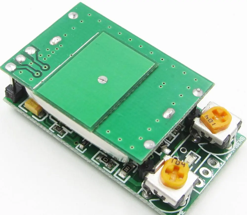
What does a Microwave Motion Sensor Entail?
A microwave motion sensor is a simple gadget instrumental for your home security system. It utilizes electromagnetic radiation and emits waves that get reflected in your receiver. Electromagnetic waves or radiations comprise oscillating magnetic and electric fields that proliferate at very high speeds (comparable to light). The receiver acts as an analyzer of the bounced back waves. For example, a typical object moving across the room will alter the waves. The receiver will then identify such alterations whenever they happen.
For a microwave motion sensor to work, it must have a corresponding motion detector. The detectors become useful in measuring the time the signal takes to reflect onto the sensor. Such a period gets inferred as the echo time. It is instrumental in calculating the in-between distances of all stationary objects located in the detection zone. The echo time acts as the baseline upon which the system functions.
Typically, the microwave motion sensor’s mode of action implies that it can either prove less or more sensitive. Therefore, you can calibrate the MMS to spot tiny changes or more elaborate movements of larger objects to avert false positives.
The properties of electromagnetic radiation or waves imply that their corresponding sensors can get classified into different types. Some important properties include wavelength or frequency, strength or intensity, and polarization. Frequency implies the change rate of the electromagnetic wave’s amplitude. It is also related to the light’s wavelength or speed.
On the other hand, the intensity comes as the measure of the electromagnetic wave or radiation’s amplitude and correlates to the energy that the wave carries. Remember, the magnetic and electric fields in the electromagnetic wave come as vector quantities. As such, they have both a direction and a magnitude.
The electric field’s direction lies perpendicular to the propagation’s direction and often defines the wave’s polarization. It can have either a linear or circular polarization. Because of the vector nature of the radiation, you find an electromagnetic wave proving sensitive to the orientation of the object it scatters from. It thus gives extra details about the morphology of the surface.
Passive Microwave Sensors
All microwave sensors operate within the electromagnetic frequency range of 0.3-40 GHz. In addition, a passive microwave sensor detects natural microwave radiations that a surface produces.
Active Microwave Sensors
It involves microwave motion sensors that emit microwaves before detecting the reflected microwaves from the object of interest under observation.
Classes of Microwave Motion Sensors
best microwave motion sensor
Microwave motion sensors come in diverse types that generally fall under the following classes. It includes the pulsed radar type, frequency-modulated, continuous-wave or FM-CW radars, Doppler-effect radars, and UWB systems. Other classes entail transmitter-receiver systems, resonator sensors, modulated targets, impedance meters, and radiometers.
Most of the microwave motion sensor classes utilize a transmitter or a signal generator and a receiver save for the radiometers. However, the distinguishing factor between the classes arises from the signal modulation type and the system’s design. Additionally, some microwave motion sensors can work when placed at a distance from the object, while others function while mechanically joined with the object.
Features of a Microwave Motion Sensor
Intrinsically Safe: Microwave motion sensors cannot generate sparks, especially from electrostatic discharge or friction.
No Contact: It can operate without establishing any contact with the object. Additionally, the microwave sensor can also successfully penetrate nonmetallic exteriors.
Rugged: Microwave sensors possess no moving components or parts and thus prove reliable. It is especially true in comprehensive military applications.
Long-range: microwave motion sensors can detect objects located from distances spanning 25mm to 45000mm or more. However, this depends on the size, antenna design, and microwave availability.
Environmental reliability: in most cases, you will find microwave sensors operating from a -55A °c to a 125A°c in dirty, dusty, polluted, and gusty poisonous areas.
The microwave sensor’s size: As technology develops, advances in microwave circuits have allowed the ultimate package to become smaller and cost less. The package often contains the transmission source, transceiver or signal processing receiver, and the focusing antenna.
Factors that Determine the Frequency of Microwave Motion Sensors
Your choice of a microwave motion sensor concerning frequency needs to get determined by various factors. It encompasses your intended application, power constraints, platform, and the availability of the desired spectrum at the preferred frequency range. For instance, you will get the following frequency bands within the stipulated wavelengths.
Wavelength Range (CM)
Frequency Band (MHz)
1.13 – 0.75
26,500 – 40,000
1.66 – 1.13
18,000 – 26,500
2.4 – 1.66
12,500 – 18,000
3.75 – 2.4
8,000 – 12,500
7.5 – 3.75
4,000 – 8,000
15 – 7.5
2,000 – 4,000
30 – 15
1,000 – 2,000
100 – 33
300 – 900
What Can a Microwave Motion Sensor Do?
You must think by now that a microwave motion sensor only detects motion through wave disruptions. However, the functional enhancements presently available on it will not only surprise you but convince you of its efficiency in securing not only your property but other advanced operations. For instance, the advanced microwave motion sensors can also sense motion towards a random motion or a motion moving away from it. Such a differentiation of motion becomes helpful in detecting normal movement from that of an intruder. Moreover, it is a feature that makes a microwave motion sensor highly reliable.
Microwave motion sensors also come as a safe product for use. You can use them outside or within your household or property. Further, you can place the sensors across a large area besides configuring them to sense or detect diverse activity types. For example, you can configure the sensor to ignore specific activities in specific areas of your property, like the kids or pet areas.
For newbies, the term doppler radar can prove sophisticated and confusing. However, it has the same meaning as that of a microwave sensor. The Doppler radar is sensitive and reflects microwaves from objects within the detection area but devoid of any temperature disturbance. In most instances, you will find doppler radars as one of three types: the planar microstrip, coaxial, and wave-guide microwave sensors.
Doppler radars bounce microwave signals off the anticipated target and analyze the object motion’s effect in altering the returned signal’s frequency. Therefore, the target’s velocity can also get measured based on the received variation against the radar. In summary, you will find microwave motion sensors using microwave technology. It, in turn, gets classified into motion sensing, velocity sensing, presence sensing, and sensing of the motion direction. Another crucial category includes range sensing.
You will possibly find doppler radars in applications such as meteorology, aviation, healthcare, military, and radar guns. But to make your own Arduino doppler radar, consider the following section.
Making an Arduino Doppler Radar
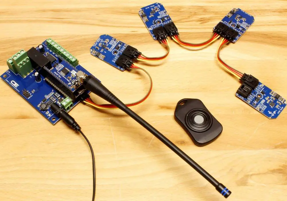
By now, you know that any microwave motion sensor must have a microwave transmitter, a receiver, and most times a related circuit or alarm. However, you must use some crucial components to develop the three. Critical components entailed in building a functional Arduino Doppler Radar entail the Arduino Nano, jumper wires, breadboard, character LCD, LED, character LCD, Buzzer, resistor, etc. It never ends here as the hardware components must get controlled via a software system.
Follow the following steps once you have assembled all the necessary components required to build a functional Arduino Doppler Radar.
Wire the hardware up by connecting the Arduino, the RCWL, character LCD, the Led, and the buzzer in the prescribed sequence. It mostly involves LED and Content with Arduino PINs of 2 and 3, respectively. Arduino analog IO of A5 and A4 with SDA and SCL character LCD. The Arduino Nano encompasses the GND, 5V, and D2, while the RCWL encompasses the GND, VIN, OUT.
It is crucial to note that the Pin 3V3 located on the RCWL comes as the output pin. Additionally, the CDS pin allows you to incorporate an LDR into the breadboard. Such a light-dependent resistor will allow you to operate the system in low-power mode. Consequently, it will (sensor) can solely activate in darkness.
You must double-check all the connections before uploading the software’s source code.
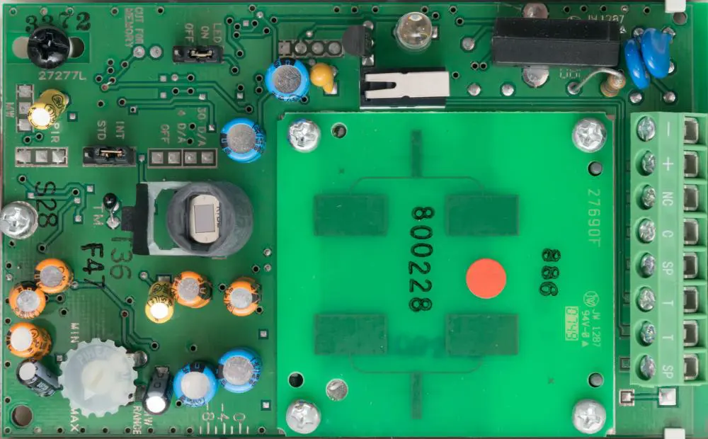
The Working Process of a Microwave Motion Sensor
For a microwave motion sensor to work, it needs all the components necessary for its proper function (transceiver, sensor, etc.) In addition, the sensors need a narrow beam and a high-gain antenna to reflect the energy to the module. However, the amount of energy will depend on the shape and composition of the object of interest.
Operational Principles
The sensor module gets developed through the Doppler radar principle. Further, the sensor module’s role encompasses the transmission of a low-power microwave from the transmitting antenna besides receiving the microwave energy reflected by objects to the receiving antenna.
When the object’s movement is detected, the reflected frequency (microwave) gets shifted from the transmit bandwidth or frequency to the receiving antenna. The shifted and reflected microwave frequency gets mixed with the microwave frequency transmit and results in a low-frequency voltage at the sensor’s output.
Detection Factors
In almost every incidence, six probable factors affect the Pd or the probability of detection in volumetric sensors – though at varying degrees. It includes the pattern and amount of energy emitted, the size of the objects, the object’s distance, speed, the direction of the movement, and the absorption or reflection features of the waves (environment or the intruder)
It is beneficial to have a more defined energy pattern in theoretical terms. Similarly, if the intruder or the moving object proves larger, you also get a higher detection probability. In the same way, the shorter the sensor distance to the object or intruder, the quicker the intruder’s movement, the higher the detection probability. Additionally, a lateral and fast movement typically has a higher detection probability than a straight and slow movement.
Upon returning the reflected energy to the transceiver, your mixer diode combines this energy with the transmitted signal. But remember, the target either moves towards or away from the module, which implies that the phase relationships between the two will change. As a result, the signal emanating from the mixer will prove audio frequency and also proportional to the target’s speed. The phenomenon gets inferred as the Doppler frequency.
Further, microwave motion sensors or detectors must be combined with PIR technology to limit false alarms. In most instances, you will come across the tech combination as a dual technology detection approach.
Prices of Microwave Motion Sensors
If you want to get a quality and efficient microwave motion sensor, you must consider different aspects. Firstly, understand the functionality of the microwave motion sensor, the different types available, and the cons and pros of each system. Additionally, it would help if you considered the available manufacturers and their reputations. Finally, but most importantly, the price vis-à-vis the quality of the Doppler Radar needs to guide your decision-making.
However, the general microwave motion sensor price range of microwave motion sensors begins from $ 0.8 to about $52.5. however, the specific range depends on the minimum order quantity the seller offers besides the type of microwave sensor. Further, wholesale prices will always prove cost-effective though this often needs a large order – otherwise not feasible for most end users.
Factors that Influence the Microwave Motion Sensor Price
microwave motion sensor range
The Brand of the Manufacturing Company
Microwave motion sensors will always come under different brand names and product lines. It implies that each will have distinct features depending on the manufacturer and product line. Such often indicate their differential quality, which then influences the microwave motion sensor price. Other price determinants of microwave motion sensors attributable to the manufacturer include the reputation of the brand or manufacturer (industry experience), size of the manufacturer, location of the manufacturing plant, and the type of microwave motion sensor. For instance, RayMing PCB and Assembly has a demonstrated history of over fifteen years in manufacturing and assembly of printed circuit boards crucial for sensor devices. Its production plant in diverse areas over the globe also makes it suitable for the global clientele.
Further, bigger companies with excellent reputations have established supplier relationships. Such relationships lead to discounts on raw materials and reduce the cost of production. What’s more? The company easily takes advantage of the affordable production costs (quality and affordable labor in China, raw materials, world-class technology and infrastructure, etc.) As such, you will not only trust the world-class products and services offered but enjoy incomparable prices with competitor companies within the industry. The result of all this entails getting high-quality microwave sensors and allied components at relatively affordable prices.
Finally, the type of microwave under a specific brand name will either drive the cost of the sensor up or down. For instance, experimental active microwave sensors will cost higher than passive microwave sensors regardless of the brand.
The proximity of the Manufacturing Company
Once the fabrication of the different components of a microwave motion sensor gets completed, assembly and distribution ensue. The latter part can drive the cost of the final product owing to shipping, especially when they have to get transported for longer distances. It is thus advisable to always go for a manufacturer or decent brand located near you.
Application Areas of a Microwave Motion Sensor
Different microwave motion sensor exists for diverse applications—the diversity in application demands different capabilities of the sensors. For example, a microwave motion sensor for home security will not have the same capacity as one used for geospatial studies. One will rely on passive microwave technology while others will entirely depend on active microwave technology. Size also plays a crucial role here as different applications prefer specific sizes. The smaller the microwave motion sensor, the less material it uses and hence lowers the cost of material in production.
Here are some of the Applications
Medicine and Physical Wellbeing. Microwave motion detectors find application in detecting patients’ breathing rates and heartbeats in hospitals.
Monitoring your Building Lighting System
You can also use a doppler radar for monitoring your light system in the house or office. It is a common feature in elevator shaft-ways besides your property’s security. You will also find it getting used in enforcing traffic rules and regulations.
Microwave motion technology not only applies in the traffic arena but also industry. For instance, you will find microwave technology in measuring the speed in vehicles, automated doors, automation lights, reversing radar, alarm systems, etc.
Another crucial application area for the microwave motion sensor entails securing areas like banks, museums, military installations or warehouses, prisons, transformer substations, etc. however, for such applications, the microwave technology needs to get combined with the PIR motion detectors. Such a combination of technologies for motion sensors enhances reliability and performance.
How Can You Benefit from a Microwave Motion Sensor?
A universal truth about microwave motion sensors entails using them in almost any environment. You can use it in most environments; especially those many can deem unhospitable for sensors. For instance, you can comfortably use it in high-heat environments that can fry photo-electric sensors. The MMS ranks as among the versatile sensor system types available in the market.
A microwave motion detector can also go through holes and walls. Therefore, it implies that you can use it to cover larger areas of your home or property, including your large outdoor area. If you, therefore, have a large area to secure, then this microwave motion sensor can prove the best option for your motion detection.
You can program a microwave motion sensor to limit the volume or number of false alarms devoid of minimizing correct positives. Consequently, you get to enhance your motion sensor’s ease of use and accuracy. Further, you comparatively spend less to buy a microwave motion detector compared to other motion detector types. It is, however, imperative to understand that running them can become more expensive.
A microwave motion sensor also covers a 360 degree-wide scope compared to other systems like the PIR, which only covers a 90 degree-wide scope.
Drawbacks of a Microwave Motion Detector
A major challenge you will most likely experience with a microwave motion detector entails the countless false alarms that may occur from slight object vibrations. It can include swinging signs, curtains, etc. Further, a microwave motion detector operates in intervals and not continuously. Because of this, it increases the probability of any intrusion.
However, the enhanced detector combats this challenge by having every component of a typical sensor besides two mixer/receiver diodes. Additionally, some sensors possess diodes that enable the sensing of the intruder’s direction to the detector.
Microwave beams have special properties that enable them to permeate almost any type of surface (around the detection shield). However, for metallic surfaces, this never proves the case. Therefore, the sensor can detect a motion in undesirable detection areas and fail to detect motion where it proves desirable. Further, metallic objects act as shields that create dead zones or shadows behind them. It is in such areas that the sensor fails to detect any motion.
Microwave motion sensors also have the predictable ability of sensing motion behind walls because of their beam. As such, it will not discriminate the motion even if it proves typical because of the sensitivity of the sensors to motion. It can always become a challenge in a home setup, especially with false alarms.
Final Thoughts?
The specter of microwave motion sensors in terms of their capability and related costs makes it an ideal fit for your domestic or commercial use. You can not only enhance the security of your premises or household with such powerful security tools but use them for other investigative, security, and explorative ventures. However, understanding what a microwave motion sensor entails, how it functions, the different types, and possible application areas will effectively kickstart your journey. Hopefully, at this juncture, you have managed to answer some of the pertinent questions you had about microwave motion sensors. You also understand where and what price range you can secure your microwave motion sensor.
FPGAs play a crucial role in any industry. It does not matter if it is modern designs or complex prototyping. They offer reliable design and manufacturing solutions. They do this by offering the best of both worlds. FPGAs have been instrumental to the success of many big organizations. FPGAs are also gaining more and more critical in the medical industry. The medical sector is a multi-billion dollar market. In addition, a vast amount of information needs analyzing. The process of them in real-time is growing at a tremendous rate. It makes FPGA technology in the medical industry an essential factor.
According to a new report published by Persistence Market Research, the global FPGA market valued USD 28.9 billion in 2016. Furthermore, we expect it to grow with a CAGR of 13% over the forecast period (2017–2022). According to a new report published by Persistence Market Research (PMR), this is according to a new report. The report also indicates that North America, Asia, and Europe will emerge as the fastest-growing markets.
FPGA History
Initially, manufacturers developed programmable logic devices to emulate custom computer chips. Xilinx invented the first PLD in the early 1980s. As a result, we often refer to it as the Xilinx device. With Xilinx’s FPGA, many companies produce FPGA, including Lattice Semiconductor and Altera.
The development of FPGAs began in the early 80s. This is with the advent of gate arrays and reprogrammable logic devices. The first commercially available gate arrays were available from Xilinx in 1984. In 1987, Altera developed the EPLD to provide customers with a lower-cost alternative to gate arrays and decoded PLDs. Today, Altera is the FPGA leader, with a market share of 60% in 2016.
The global FPGA market is around North America, Europe, Asia Pacific, and the Rest of the World. Among these regions, North America was the leading FPGA market in 2016. It accounts for a market share of 40.8% in 2016. We expect the market to grow at a CAGR of 9% from 2017 to 2022 n projected by 2022.
The revenues from the European region were USD 7.8 billion in 2016. We expect it to grow at a CAGR of 13% during the forecast period.
The Asia Pacific FPGA market will show considerable growth with a CAGR of 17% from 2017 to 2022. This is due to the growing demand for mobile devices and other consumer electronics. It uses FPGAs as semiconductors. In addition, the increasing demand for smart wearables will further fuel the growth in this market.
How FPGA influences technology in the world
FPGA technology is also revolutionizing the gaming industry. Several faster and more powerful gaming platforms are being introduced in the market every year. Newer PC games are now demanding more from their processors and graphics cards. It has led to a huge demand for these technologies
In addition to gaming, FPGA technology also has a huge impact on other industries. The development of new improvements in FPGA has changed the way data center servers are performing. FPGA technology is helpful in high-end supercomputers. Such technologies can conduct calculations and simulations that traditional chips cannot perform. The Financial sector has also used FPGA technology to process large amounts of data. It has led to significant improvements in cryptocurrency mining.
One of the lesser-known companies that produce various products is an Australian company called Xilinx Incorporated. This company has a reputation for being one of the more advanced companies in the production of very high-technology.
Xilinx is a manufacturer that produces integrated circuits. Why are integrated circuits essential, you might ask? They are responsible for making everything work better, faster, and using less power. This is ideal because of the rapid development of technology and because we don’t always want to drain our batteries all the time.
One of the most popular integrated circuits that Xilinx produces is an FPGA. This stands for Field Programmable Gate Array. But, again, what does this mean? We can configure this type of integrated circuit in many different ways and areas.
The company Xilinx has been producing FPGAs for several years now. They have managed to produce different FPGA models, all suited to certain uses. This has meant that even though their FPGAs did not dominate the market for long, they are still very popular.
Another thing that makes Xilinx stand out from the crowd of FPGA producers is that they produce the chips and software and hardware integration tools.
2) Altera Corporation
Another FPGA manufacturer that has been around for several years is Altera Corporation. Just like Xilinx, this company is also one of the top FPGA companies in the world.
The company was founded in 1984 and is in California. Since 1984, they have been continually producing high-quality products and are now one of the world’s best-known companies. Altera Corporation manufactures FPGAs for several different uses. These include the fields of industrial automation, microprocessors, and consumer electronics.
The Altera Corporation is the third-largest FPGA manufacturer globally, after Xilinx and chip giant Intel Corporation. The company holds around 35% of the market for FPGAs in total. For this reason, quite a few technology companies are using their products.
Altera Corporation had designed chips for NASA to build their Mars Rover. They have also made chips for the European Space Agency and the US Military. This is because of the high quality that Altera Corporation produces.
Another very influential company in the world of FPGAs is Lattice Semiconductor Corporation. This company was founded back in 1997 and has quickly risen to become one of the top FPGA manufacturers.
Lattice Semiconductor Corporation focuses on making products too complex for individual companies to produce. These include chips made just for the needs of a particular company. However, the lattice has also become very successful at producing adaptable chips to be used in many different applications. This is why they have made such a name for themselves as a top FPGA manufacturer. They make the chips helpful in everything from high-tech medical equipment to workstations and even video cards.
The company has won many awards because of its products used in many different applications. They have won the “Best Products of the Year” award and the “Technology Innovation of the Year” award. This is all because they produce such high-quality products.
Achronix Semiconductor Corporation is an American FPGA manufacturer that has been in the game since 2003. This is not a very long time, but it is certainly sufficient time to become successful.
The company concentrates on producing ultra-small FPGAs used in many different applications. These include use in military and medical systems as well as consumer electronics. As a result, the company has managed to produce some of the smallest FPGAs on the market today, allowing them to compete favorably with other manufacturers.
Achronix Semiconductor Corporation is also one of the few FPGAs manufacturers to produce and sell baseband processors. These are chips used in wireless communication, and they have managed to get themselves an excellent reputation in this industry. It focuses on data center, networking, ML, AI, and 5G, which is why the company has become so successful.
QuickLogic Corporation is another FPGA manufacturer that has achieved good results over the past few years. However, unlike many other companies on this list, QuickLogic does not produce just high-quality FPGAs. Instead, they also produce high-quality ASICs and other components.
The company originally started as a GLOBALFOUNDRIES spinoff and was started in 2006. Since then, they have grown to become a very well-known and successful company indeed. Their products are helpful in many different applications and many different types of industries. They have been involved with some very high-profile companies in the past, including Google, Cisco, and Marvell.
QuickLogic Corporation is often responsible for designing chips for other high-profile companies. Many chips you will see in the devices you use daily, such as cellphones, have been designed by QuickLogic Corporation. This means that they are one of the most successful FPGA manufacturers on the market today.
Another very well-known company in the FPGA industry is Microchip Technology. This company was started back in the 1980s and has become one of the top microcontrollers and other microprocessors.
PJ Rodgers, a very successful businessman, founded the company. They have been able to branch out into many different markets to expand their business. Perhaps their most famous product is the hugely successful PIC microcontroller.
Microchip Technology has also produced a range of FPGAs called Microchip’s Multimedia Module. These are chips used in many different types of devices, including set-top boxes and video cards. These FPGAs are known for being very high quality and have won many awards because of their high performance. They have even been able to win “Best in Class” awards from the Electronic Design Magazine.
Microchip Technology has also designed and produced RFID chips. This has allowed them to carve out a niche in this market, which is why they are one of the biggest FPGA manufacturers.
Another FPGA manufacturer which has seen a lot of success over the years is Microsemi Corporation. This company is one of the largest COTS manufacturers globally, so you will see their products in many applications worldwide.
The company was founded back in 1983, making it one of the oldest companies on this list. This means that the company has had plenty of time to perfect their products, which is why they are now so successful.
Unlike Altera and Xilinx, Microsemi does not produce FPGAs for just any use. Instead, they concentrate more on providing their products to military applications and scientific ones. This is why many of their products are often helpful in government contracts and research endeavors.
Microsemi Corporation has worked with Qualcomm, a very influential communication company. They also have their line of FPGAs, which are called SmartFusion. Microsemi Corporation has recently released a new version of this range called SmartFusion2. This is because the technology within these chips has significantly advanced since the release of the first versions.
Efinix Corporation is another well-known company in the FPGA industry. They were founded way back in 2000 and have since become one of the top FPGA manufacturers on the market today.
Efinix specializes in making very small FPGAs complex enough for customers to use as high-level control chips for other chips and devices. They are known for making incredibly tiny components, which means that they can be helpful in all sorts of different markets. For example, they are essential in the manufacturing industry and consumer electronics.
The company also manages several other subsidiaries, including a chip design company, a design services and research center, and an RFID supply services business. They have also branched out into the Semiconductor Open Source Hardware (OSHW) market. This allows people to build their own FPGA boards legally.
How to select a good FPGA company
Let’s face it. It is not easy to choose a supplier of embedded FPGA solutions. First of all, finding a good FPGA company is a lot like choosing an investment advisor. For example, you can pick one of the top companies above based on price, quality, and reputation. However, this approach has some obvious advantages.
The best advice to selecting the right embedded FPGA solution is to pick a business partner, not a product provider. This means you should know what sort of company you are dealing with and how it operates.
1. SOC-based board or an FPGA?
An integrated SOC-based board. It includes an FPGA that can sometimes provide a higher level of performance than an FPGA on its own. However, the performance difference may be small.
A good FPGA board can sometimes offer better performance in certain applications than a good SOC. For example, an excellent FPGA-based wireless modem might perform better than an off-the-shelf SOC modem. Unfortunately, no company has integrated SOC and FPGA that provide better performance. This is why most FPGA companies are also selling SOCs. It is because many customers want both the SOC and the FPGA.
Some embedded FPGAs provide an integrated processor and SoC in a single chip. Still, they provide a poor level of performance. This is due to high power consumption. Also, it is due to a lack of flexibility in integrating the processor with other components in an SoC design.
2. Interfaces and IOs
The number of interfaces and IOs must be sufficient to support the application. Some FPGA companies provide FPGAs with over 1000 IOs. However, if the application only requires a few IOs, it would be a waste of money to use an FPGA with over 1000 interfaces and IOs. The optimal number of IOs will also depend on the software used.
Some FPGAs provide greater flexibility by supporting interface standards. Examples include PCI, PCIe, or USB 3.0, which are not commonly available in SoCs and SOCs.
3) Ease of use
It is not easy to program an FPGA, whether it is a SOC-based board or just the FPGA on its own. Therefore, some companies provide a software development environment for their product. This removes some of the complexity in programming embedded FPGAs. Others provide a set of libraries that simplify programming embedded FPGAs.
Using an existing software development environment to program an FPGA may be possible. Some FPGA companies provide free development tools or host code. But, these tools and libraries do not always work well with all embedded applications.
The ease of use will also depend on the FPGA company’s software and hardware support.
The most flexible FPGAs depend on a multiple-core approach. It has multiple configurable logic sections. The logic sections include an FPGA fabric. In addition, it provides programmability and an embedded processor core. This approach allows you to program a single chip to perform multiple tasks.
The best FPGAs have an FPGA fabric that supports high-performance logic and embedded processor cores. So, the embedded processor core improves performance. However, we can achieve this through extensions. We can also do it through optimized versions of standard cores that the company sells in standalone FPGAs.
5) Open source or closed source?
Some FPGAs are open source, which means that the code for the FPGA is available on the internet. The most common FPGAs in a SOC-based product is open source. However, some companies also provide closed-source FPGAs. An example is the Synopsys 21Gbit Coherent Accelerator Platform.
Most FPGA companies sell their FPGAs through distributors. In addition to selling the hardware, the distributor will also support the end-user. They may also provide training on how to use the hardware and software. But, this is not always possible due to time and travel constraints.
The best-embedded FPGA suppliers provide end-users sales, technical support, and training. A company’s distributors can provide these services.
6. Buttons, LEDs, and Displays
Some embedded FPGAs provide buttons and LEDs. Others have more advanced user interfaces. If you need more buttons, LEDs, and displays, it is easier to use an FPGA that supports the standard user interfaces already present on a computer. Knock-on effects of supply chain security and reliability
If you are having trouble picking an embedded FPGA company, it may be because of:
• The lack of information that is available to compare these companies. This can make it challenging to choose the right product and company.
7) Memory and Resource Count
The application determines the resources required for embedded FPGA solutions. Some applications need very large amounts of memory, while others do not. It is also possible to find embedded FPGAs. They provide higher performance than standalone FPGAs. They do not need as much memory and limited resources.
An FPGA with a higher memory capacity may be more suitable. However, some embedded FPGAs depend on a very large internal memory and do not need much memory at all. The best-embedded FPGA companies overcome these issues. You can do this by providing access to external memory through an interface.
8) Power Consumption
It is possible to find FPGAs that consume very little power. Examples include Cypress CY8C27x25 and Green Hills GLCM2-6XC57-E). The best suppliers can provide up to 10 W of power consumption. In addition to its power consumption, we can determine the power rating of an FPGA by its technology. Other factors to consider
Most FPGA suppliers provide support for their products. However, if you need help with the development, Rayming PCB & Assembly offers free or paid software development tools and libraries. In addition, some FPGAs provide a variety of interfaces. They include USB, Ethernet, and PCIe.
Via the xPort family of high-performance connectivity FPGAs, Xilinx provides the Xilinx iGate. It enhances the flexibility and performance of existing embedded memory designs. It connects them to the I/O interfaces, an SoC or SOC. The high-performance interface enables easy communication between microprocessors and embedded memories. This enables customers to develop systems with enhanced performance and increased cost savings.
The toolchain will also determine which FPGAs you can use. For example, running the software on a standalone FPGA may be necessary. Especially if a set of libraries from your software development environment is not compatible with an FPGA.
Some embedded FPGAs have a simplified toolchain that works with an existing embedded platform. However, we need other tools, which often cost more than the basic toolchain.
It will also be necessary to choose the correct FPGA for your system. Usually, there is a trade-off between area space and the number of logic elements (LEs) in the FPGA.
The number of LEDs available in an FPGA can vary from 4K LEs to over 1M LEs.
10. Programming Interfaces
The programming interface will determine how easy it is to program your FPGA. The best companies provide programming interfaces compatible with industry-standard tools. The most popular programming languages for embedded development. This allows designers to use the same programming tools and libraries.
Some embedded FPGAs provide an industry-standard programming interface. Others may need to buy a tool or software development kit. Buy a tool that allows access to the internal hardware of the FPGA.
11. Learning Resources and community support
While some embedded FPGA suppliers provide technical support and training, others do not. Some suppliers provide a forum where users can ask questions. However, suppose you do not receive any support from the supplier. In that case, it may be necessary to hire a consultant. One that can help you with your development or troubleshooting issues. For example, Xilinx HW-Acceleration Center.
The best-embedded FPGA companies know that customer support is essential. So they use it to create robust and reliable products.
12. Operating Temperature
The operating temperature of an embedded FPGA will depend on the physical environment. For example, some environments need the use of an embedded FPGA. Therefore, they should have a higher operating temperature.
We can measure this with the help of a thermal camera. This is to determine if the device is working under stressful conditions. If your FPGA is essential in a warm environment, it might be possible to use it in a cooler area by using heat pipes. However, be careful not to overheat your FPGA.
13. Security and cross-platform support
Some embedded FPGAs will have some security features that are not compatible with other platforms. Therefore, it is essential to determine if you can use the same security libraries and tools for other platforms with an embedded FPGA.
Some embedded FPGAs use security features that are not compatible with other platforms. For example, most suppliers provide a TPM or secure boot option enabled by default.
14. Cost
The cost of an embedded FPGA depends on the design and implementation of the product.
Some FPGAs are very expensive, while others are cheaper.
To help reduce the cost of your embedded FPGA, some companies provide a similar product for less.
15. Availability and longevity
The FPGA life expectancy will depend on your application. While some will live for a long time, others may only last for a few days or even weeks. Therefore, you should determine the expected life expectancy from the FPGA supplier.
16. Environmental Factors
Your embedded FPGA will operate in various environmental factors. These factors might affect its performance and operation. The quality of the material used for the FPGA will affect its durability.
Conclusion
The embedded FPGA market is growing. This is because more companies and individuals appreciate the benefits of using FPGAs. So, the number of suppliers should also increase. As a result, the embedded FPGA market is expanding. It will be interesting to see how these markets develop soon.
Suppose you are looking for an embedded FPGA development kit. In that case, you should look for a supplier that supports their products. They should also provide a way to overcome embedded FPGA development challenges.
Altera and Xilinx are already integrating FPGAs into their application development toolchains. This means that we can program FPGAs alongside other processors and microcontrollers. Therefore, if you are working on a new embedded application, you should consider using an embedded FPGA development kit.
The printed circuit board is a flexible element used across various industries. Its acceptance cuts across the technology and the electronic industry due to its unique attributes. Its copper density is a crucial factor in fabricating a standard PCB. The conductivity role played by the copper is essential to the Printed circuit board.
The Printed circuit board depends on electricity to carry out its infinite functions. The nominal circuits in the board are the pathways by which electric currents move from one place to another without hitches. Copper is a standard carrier due to its conductive nature.
The copper performs well as a high conductive component. It is possible due to the valence electron it possesses. Electrons convey electrical signals that form the foundational particles which hold electrical charges. The copper density carries the electrical signals without ditching electricity.
Furthermore, Copper density is also known as copper thickness or copper weight. It is in the sq ft. area of the circuit board. The Coppers’ measurement is in ounces (oz/ft₂). Its thickness determines the current-carrying strength of the whole Printed circuit board.
Making a wrong choice of copper density during the PCB designing process could ruin the performance of the PCB. Thus, understanding the connection between signal conductance and copper weight is crucial. It would help make the right choice of copper density for the PCB.
The thickness includes 0.5 oz copper thickness, 1.0 oz/sq ft copper thickness, and other types of density measurements available. Going through this article will help deepen your knowledge of PCB copper density. It will also supply adequate information on various copper densities.
Copper is one of the essential components of a printed circuit board as a great conductor. Choosing the perfect copper weight type during the fabricating process helps avoid issues that could affect the functionality of the PCB. The copper is a strong basis on which the PCB thrives. It serves as the connector of every component around the circuit.
Electronic designers mostly relegate components such as the PCB copper weight and the board thickness to the background. The copper density adds to the whole thickness of the external layers of the PCB. Its importance is significant to fabricating a standard PCB.
The copper density or weight are of three different specifications. Each classification has its analytical role in the PCB manufacturing process. As a very strong conductor of current, its measurement is in ounces per square foot.
Classification of the Copper Density
Standard Copper Weight
This copper specification ranges from ¼, ½, 0.5.oz per sq ft to 4 ounces per square foot. It has been the measurement in use for a very long time. Using this type of copper density reduces the risk of failure in the printed circuit board.
Heavy Copper Density
The weight for this kind of copper density ranges between 5 to 19 ounces per square foot. The heavy copper surpasses the standard copper in diversifying the PCB design. It offers more room for creativity and experiment.
Extreme Copper Density
This density weighs around 20 to 200 ounces per square foot. To fabricate long-term designs, designers choose an extreme copper density. It involves laying two copper densities on a single PCB layer. Also, it removes the need for several standard copper plates. It also enables designers to place a small quantity of extreme copper on the exterior layer of the board.
The extreme copper density on the PCB allows the carriage of more current. However, there are other copper densities available. They include:
What is 0.5oz PCB Copper?
Several PCB designs require specified copper density to meet the electrical current demands of the circuit. To choose an appropriate copper density to fit the design hinges on the type of PCB. The 0.5 oz copper thickness in mm is also called ½ oz copper thickness. It is the copper measurement type that forms part of a non-standard fabrication. It is obtainable in the inner layer of the design.
The 0.5 oz copper thickness approximates a piece less than 0.0007mm. It is an uncommon option for small products and appliances with less conductivity. The size of this copper type is a unique option among manufacturers. Its thin size exposes the design to overheating in contrast to other copper weights.
It is important to note, designs that require 0.5oz or 1.0oz’s electrical difference are trivial. The copper thickness in the circuit board does not have a standard measurement. Fabricators could choose the perfect fit for their design. It could be at 0.5oz/sq ft or 1.0oz/sq ft thickness.
The main difference between the copper thicknesses and other types is the direct current resistance. PCB with a high copper foil impacts the direct-current resistance on the planes and traces. Therefore, dispersing direct current around a large PCB, there could be a voltage drop.
It is the primary density for the printed circuit board. Having sufficient copper in the design secures a perfect working condition in the PCB. The 1 oz thickness is the standard copper density on the outer layer of the PCB. It is one of the most popular flex PCB copper weights.
2 Oz Copper
A 2 oz copper PCB is a design that has a copper weight per square foot at two ounces. It is the internal copper density of the inner layer in the PCB. It is on a 3oz complete copper selection. The 2 oz copper is perfect for appliances with bigger current demands.
Fabricating a bulletproof PCB with high capacity requires heavy-weight copper. This type of copper density is highly reliable, and it has comparative advantages over the thinner copper types.
Conclusion
By now, you should have gained much knowledge about half oz PCB. Copper is an exceptional conductor, and it plays a crucial role in the fabricating process of the PCB. Therefore, choosing the perfect copper density to suit the application is essential. A wrong choice will deter the performance of the board design.
One of the ways to improve performance is through increasing the operating speed. Taconic now offers a platter-type PTH with a flywheel drive that achieves superior efficiency. It does this by generating energy at twice the normal speed and returning it. We can achieve a small size thanks to PCB technology with this improved performance and design.
The new PCB design produced by RayMing PCB and Assembly goes even further by combining vertical and horizontal power supplies. This results in increased flexibility and easy replacement of individual power supplies without disrupting the flow of electricity throughout the machine. It offers these features combined with the audio and data functions and low power consumption expected of a PTH. IF NECESSARY, the PCB can be easily removed or replaced, making this PTH appropriate for use in critical areas, such as hospitals and hotels.
Another essential feature is the “auto-power on” function. If we do not use this function, there is still no need to connect an AC power source to start up the machine.
The high-performance Taconic TLF-35A also features a lightweight, compact body that we can easily carry and install, a large LCD, and easy operation.
An interesting detail here is that you do not need a power source to start up the machine.
The time from power on to final buffering can be as little as six seconds.
One main objective of the Taconic TLF-35A is to reduce power consumption by as much as 30% compared to conventional PTHs. For example, a platter-type PTH such as the Taconic TLF-35A uses only 10W at maximum, compared to 20W or more in a platter-type PTH. On the other hand, other functions use lower amounts of power. The PCB design is another essential factor in the reduced power consumption. We can easily replace the PCB of the Taconic TLF-35A with another PCB.
Even when we make a replacement PCB, it takes only 60 seconds or less to get the machine up and running.
Another essential feature is the auto-power on the function that starts up the machine immediately at power on. There is no need to connect an AC power source with this function.
The auto-power on the system allows operation in environments where fluctuating power might influence how long it takes to start up. In addition, we can use the machine with a remote-control unit, if necessary.
The PCB allows for a low-cost installation of the tray. Also, we can easily replace and the motors. We install a new PCB in only 60 seconds or less to get the machine up and running.
Size
Compared with other PTHs with platters of 35cm in diameter, there is only about one inch more of playing surface on the Taconic TLF-35A. The PTH weighs only 3.5kg, less than 4kg (certainly lighter than most conventional PTHs).
Many companies build Laser pickup and servo control into the Taconic TLF-35A.
The Taconic TLF-35A is also small compared to PTHs with a bevel-type data system.
This PTH is small enough to transport by hand.
We can remove the top and bottom covers by loosening the thumbscrews on both sides of the platter. Then, we install a new PCB in only 60 seconds or less to get the machine up and running.
The Taconic TLF-35A is so light that one person can easily carry it, making it convenient for carrying and moving.
The LCD (1.6 inches) shows pitch, rpm, and track numbers.
Why you should use the Taconic TLF-35A PCB
The Taconic TLF-35A PCB is a very convenient product. You can easily carry the PTH and install it in the customer’s location. In addition, the time required to start up the machine (after power-up) is less than six seconds.
Suppose there is a problem with one PCB, only that PCB needs replacement, and then we can use the PTH immediately. There is no need to replace all of them, as in other machines.
1. Very high thermal reliability
Because the PTH is small, we can use it on a desktop or a shelf. Consequently, the thermal design is very critical. Also, because the main power supply uses an inverter, there is not much margin for error in heat. Basically, with other PTHs such as conventional ones that use a bevel type data system, this would not be an issue if the signal does not drop off too much, not enough to cause problems.
2. Compact and portable design
The Taconic TLF-35A is so small that we can easily carry it around. It weighs only 3.5kg which is very light compared to most conventional PTHs. Its size is only about one inch larger than a conventional PTH with a platter of 35cm in diameter, although the playing surface is much bigger since it has a platter of eight inches in diameter.
To move around, you can carry the Taconic TLF-35A by hand or place it on the shelf. We do not need any special vehicle. We can easily install it in difficult-to-access locations because of its compact design and lightweight.
3. Low moisture absorption
The highly conductive PCB makes the Taconic TLF-35A suitable for hotels and hospitals where the environment is not very stable.
No matter how long it has been sitting in a customer’s location, if there are problems with the PCB, we can easily replace it and use the PTH again immediately.
4. Exceptionally low DF
Reducing the attraction force is very important for this type of PTH. Also, since the PTH is so light and small that we can move around quickly, it is essential to ensure it does not move unexpectedly. The built-in optical sensor in the platter provides exceptional accuracy.
The Taconic TLF-35A has a DF of less than 2m (1/3N). This is a very low value. DF is a standard measure of the amount of force that pulls a disk in one direction.
5. Low-noise turntable
The Taconic TLF-35A uses laser pickup and servo control, with very little noise and high stability. We must replace the PCB when there are problems with performance since there is no need to replace all of them as in other machines.
6. Excellent peel strength
Peeling a CD is not difficult if the force on the disc is strong enough. However, many paths have problems with this. This problem is that each platter in a conventional PTH has a separate motor for rotation and thrusting. This type of machine makes a great deal of noise during peeling.
The Taconic TLF-35A uses one motor to do both, so there is little noise and excellent stability during peeling.
7. Low cost
The cost of the Taconic TLF-35A PCB is much lower than that of a conventional PTH.
Each cartridge (platter, motor, pickup, and PCB) costs approximately $300. So, if you purchase them in bulk, they cost less than $100 each.
The Taconic TLF-35A is excellent for use in any place where the environment is not too stable. Also, the Taconic TLF-35A provides excellent performance. So, we can also use it to play audio CDs recorded with a PC and not with a CD recorder, as usually is the case.
This is an automated PTH that can play audio CDs and not record them. For example, if you want to playback songs stored on your computer, you can use this machine.
1. Filter, coupler, splitter, combiner, and mixer
We can use the Taconic TLF-35A to route audio signals. The built-in optical sensor makes it easy to align the disc with the sensor, and therefore, it is easier to plug into any system. (The coupler, splitter, and combiner work the same way.)
2. Antenna
The Taconic TLF-35A has a pre-amplifier and a mixer that make it easy to connect to an antenna. We can use this type of PTH for a PC or other device with an antenna such as a TV or VCR.
3. High power Amplifier, TMA, TMB, LNA
The Taconic TLF-35A is significant in high power amplification. We can achieve this by using the TMA. Generally, we need a high-power amplifier when we use an antenna as the input source of the PTH. The TMB is also available if required.
To connect to a PC via a S/PDIF interface, we must connect a digital transmission receiver that uses the USB interface to the “SPDIF Out.” We can achieve this by using the TMB.
4. Power Supply
A power supply is not required since the main power supply is an AC inverter. The DC input is 5V and 100mA and can power a PC with a USB interface if necessary (for example, to connect to the PC via a S/PDIF interface). Also, we can use the USB interface for data transfer from a PC to the PTH.
5. Repeater
The Taconic TLF-35A has a built-in repeater, so it is possible to connect to the Taconic TLF-35A by using an antenna and from an antenna. This is possible because of the flexible design of this PTH. The default settings are connecting the PTH to an antenna, but if you want to use the wireless LAN function, “Wireless Control” is available. This mode uses a wireless connection using the 802.11b standard.
6. Passive components
It is possible to use a 100V switch mode or a standard AC power supply. The power consumption is approximately 4W.
7. Decoupling circuits
Many electronic components contain some static electricity. Some of these components can reduce static discharge when used in sensitive components such as CD players. Using these parts can prevent damage to the sensitive components when used under specific conditions.
8. Medical scanners
We can use these to read the medical data from a patient’s pulse, etc. These medical scanner designs are industrial PTHs. This type of PTH has many functions and can apply RF energy when necessary.
Conclusion
A significant feature of the new Taconic TLF-35A is increasing performance through PCB technology. The Taconic TLF-35A is ideal for use in hospitals and hotels. We must always connect an AC power source because it can be easily handled and transported, and we can remove the AC power cable when not in use. The new Taconic TLF-35A comes with a three-year warranty period.
The PIMD, not unlike the predecessor TLF-35A, will produce some of the best-sounding music you’ve ever heard in your vehicle. The Taconic has only four channels and has a PLL design susceptible to radio interference. We can nullify this radio interference by using a soft muting feature in which the unit mutes for about two seconds to clear out noise in the radio frequency area.
The fast pace in technology development has brought innovations in Bioengineering. These innovations have also given rise to many software-based devices. The devices can help control the current patterns of human activity. The medical field is by far the leading consumer of these devices. The demand for such equipment is so high. The high demand it has prompted several companies to develop new designs. They are also developing designs for their products in the reaction. Companies such as Rayming PCB & Assembly have developed a modernized product line design to meet their consumers’ demands. Their new device is a lightweight EMG monitoring system. They have unique designs that we can explicitly use in hospitals or other medical facilities. Medical professionals continuously monitor a patient’s heart rate and blood pressure levels. It is easy to know what jobs using EMG sensor, you can do.
What is an EMG sensor?
An EMG sensor is a small device used to monitor the electrical activity of muscles. Medical professionals use this device to help diagnose patients suffering from muscular pains. The frequency of electrical impulses generated by the muscle can tell the physician a lot about how injured the patient’s muscles are. This will inform what type of therapy they may need to accelerate their recovery process.
Historically, physicians have been monitoring muscle activity through direct contact. They use electrodes placed on the patient’s skin. Such methods have provided accurate readings during the monitoring process. But they are highly invasive and time-consuming. This made such methods unsuitable for long-term monitoring and treatment.
For this reason, medical professionals decided to use ultrasound to help track muscle activity. Medical professionals can see a live ultrasound feed on the track. This allows them to directly assess the muscle movements of their patients from a safe distance. This made monitoring patients’ muscle activities much easier. It also significantly improved their recovery process in most cases.
EMG sensors use one of two methods to monitor muscle activity. You may design them to pick up ambient signals from the patient’s muscles or have electrodes embedded into them. We usually pick up the ambient signals using a combination of the surface. Additionally, we apply fine-wire-based electrodes directly onto the patient’s skin. Then, The EMG sensor picks up the signal, which the medical professional may hold. They may also attach it to a wearable device such as a holster-like strap.
1. sEMG sensors
We can also refer to it as the surface EMG sensor. These sensors can pick up the electrical activity from muscles and tendons within an entire body. We do this type of monitoring by covering a patient’s entire body with electrodes while placed in a prone position. The result is that we can covertly monitor the entire patient’s movement when fully clothed. The advantages of using the sEMG sensor are lightweight and very portable. They are also easy to use by medical professionals. Several professionals are conducting numerous research on this type of EMG sensor. They are much easier to troubleshoot when problems arise. The main drawbacks of sEMG sensors are that they have limited life cycles. This is in comparison to other types. If ripped off the patient’s skin, they are easily damaged and rendered useless.
2. Intramuscular EMG
Physicians usually place these are EMG sensors directly into a patient’s muscle. They monitor the muscle movements on such a close level. It helps them tell when there is an increase or decrease in blood flow to certain areas of the patient’s muscle. They use this type in patients with acute or chronic wounds and injuries. They also use it for other related conditions for which long-term monitoring of the patient is necessary. This type of monitoring allows medical professionals to assess the condition accurately. It also helps them track and progress of the patient’s healing process.
3. Deep Tendon EMG
We often refer to this type of EMG sensor as muscle biopsy. It is similar to the sEMG in many ways. The only major difference is that this type monitors mainly tendons. The deep tendon EMG has been around for longer than the sEMG. It is more reliable in terms of quality and accuracy when compared to other types of EMG sensors. The main drawback of this type of EMG is that it needs a very highly trained medical professional to apply and monitor it. This makes the monitoring process of patients in an acute state extremely difficult.
4. Intracortical EMG
This type monitors signals from the cortical neurons within a patient’s brain. These sensors are usually applied to the brain’s motor cortex using a craniotomy. We can also apply their other surgical procedures. It allows doctors access to the area underneath where they can apply the sensor directly onto the part of the cortex. We use this sensor mainly to monitor and detect changes in a patient’s motor skills. It primarily applies to patients whose injuries may be too extensive for sEMG sensors to detect accurately.
How EMG sensor work
If you was to learn how to make EMG sensor, you first need to understand how it works. An EMG sensor is a small, lightweight (usually less than 1.6 ounces) piece of medical equipment placed on the patient’s skin. We typically connect the EMG sensor monitor to the patient. We use a cable that connects to the patient’s computer or a specialized package that connects directly to the patient’s computer. This format enables the monitoring of usable data from multiple patients at once. It also offers an easy way for users to exchange data from one set of monitors to another.
The EMG sensor works by getting close to the patient. Since it is small and light, we can easily place it on the patient’s skin. Once connected to the patient’s computer, any change in the electrical activity of muscles triggers an alert signal. So, we can send it via email or through a wireless application at home. The EMG monitor then provides medical professionals with crucial information. The information can help them make critical medical decisions in their patients’ best interests.
We can make an EMG monitor using different components. It can consist of a kit that allows users to monitor a few muscles in the patient at once. We may also design other monitors to monitor many muscles simultaneously. Usually, the larger the area we monitor, the more complex and expensive the design.
These devices generally consist of medical-grade plastic that is lightweight and durable.
Software Interface of Arduino-based EMG sensor
A software interface is a computer code that facilitates various hardware devices. An example of this would be the interface between a computer and an internet security system. With many commercially available products such as Arduino, we must make the interface case-by-case.
For example, one may want to connect to an EMG (electromyogram) sensor. They may also not connect it to other bio-telemetry sensors that do not offer standard protocols. These are protocols required for easy integration with standard programs on the market today.
We can sample the Arduino analog input using the analogRead function of Arduino. We can use the Arduino to read the signals from the EMG sensor and send them to a PC for processing and analysis. The apparatus used in this project is a simple EMG amplifier circuit that they built and amplified for use with an Arduino (Arduino). The amplifier amplifies the received signals 100 times. This easily transforms them into a digital format that software can record and process. The ADC (Analog to Digital Converter) is the device that converts an analog signal into a digital format. The ADC uses a series of switches to measure the voltage coming from the sensors. Then flip it into binary values displayed on a PC screen. We need to install the driver for our Arduino board to have a functional connection with the computer.
The Interface Circuitry
One can make the interface circuitry for the Arduino of 16 pins, as shown in the figure. We use the first eight pins to connect the Arduino to the PC.
We use a voltage divider circuit to measure voltage. This is the voltage coming from two previously connected sensors and amplified multiple times (100 ×). In our case, we will be using two sensors to reproduce a signal that can track whether a person is in pain. We will use the first sensor to track the rotation of the thumb, and the second sensor will monitor the movement of the index finger. We use the voltage divider circuit to ensure that we can measure any change in output value that is coming from our amplified sensors. This circuit is a very simple but effective way that helps us capture a signal that we can easily process by using Arduino software.
We can connect the Arduino to the PC using a USB cable. The board has a built-in power supply that uses the 5V pin to power the circuit and charge the battery. We will also have to connect a small motor to create real-time results. Then we can use it to simulate a finger movement and track if it has caused any movement in our thumb’s joints and muscles. The Arduino provides us with processing information from the sensors to send it to our computer.
We must handle all electrical equipment, including medical devices, with care and caution. When dealing with high voltage electronics, there is always a risk of electric shock that any exposed part of the device can cause.
We should always turn off the electrical connections when not using them. In this situation, we connect the Arduino board to the computer via a USB cable to transmit and receive data over a computer network. When we don’t need this data, we can disconnect it.
When working with any electrical devices, be sure to use protective equipment such as rubber boots and rubber gloves. This ensures that the user remains safe from any possible electric shock while handling the equipment. You should always keep any exposed wires on the device from the user’s body during operation to avoid possible electric shocks. The general rule for working with any electrical device is to avoid touching the exposed wires with the body. Ensure that you use protective equipment whenever needed.
Safety is essential when working with high-power devices such as an EMG sensor. This device delivers a large amount of electrical current. So we must handle it carefully. It helps us avoid possible contact burns or any other harmful effects from improperly handling this equipment. It is essential that the user read all safety warnings before using this equipment. They should always follow all of the manufacturer’s safety precautions.
Essential components
Connecting Wires & Jumper wires: If a servo motor is in use, you should also power the Arduino. The Arduino cannot power the motors directly but only send power through a power supply circuit. Similarly, if you use a small motor, you should power it using a separate power supply.
9V batteries: Using 9V batteries to power the Arduino is not efficient. It is inefficient, especially when powering it with a battery charger and a DC source from an external source such as a wall socket.
A 3-lead connecting cable: We use this for connecting the circuit to a PC. You will need 13 cm of cable for each connection.
52mm electrode pads: These are electrodes attached to the skin. They consist of conductive gel and offer a reliable connection to external electrical equipment.
AD8226-based EMG sensor: It is one of the most common EMG amplifiers used in EMG sensor projects. This device can amplify and convert the EMG signals from the electrodes.
Arduino UNO: This is an Arduino board that we can use in various projects. It is one of the most popular and easiest boards in building projects based on hardware.
Arduino IDE: This program file allows the programming of Arduino to use a graphical user interface. The IDE’s code editor also provides syntax highlighting and auto-commenting tools for any code written by the user.
Arduino code: We then upload this code onto an Arduino board.
Interfacing EMG Muscular Signal Sensor with Arduino
We use EMG sensors to monitor muscular activity in humans and animals. Data is continuously acquired from the sensors by a computer. You can then process it and interpret it into helpful information.
This process involves processing signals from the electrodes. Then, you amplify them before translating them into a form that another system or machine can understand. This form of data is also called an EMG signal, muscle signal, or muscle event.
1. Electrode Connection
We apply the electrode pads to the skin of a subject. Then, we must connect these electrodes to the EMG sensor through a connecting wire. We frequently do this by placing one of the electrodes between two metal contacts placed on the EMG sensor circuit itself. The connecting wire is then attached to these metal contacts. This completes the circuit. It allows for the reading of EMG signals by the sensor.
Yellow electrode:
This reference electrode allows the Arduino to determine which electrodes we are using. We place this electrode on the skin between two other electrodes and act as a reference point. You must also connect it to the sensor’s power supply to get a stable reading.
Red electrode:
We use this electrode to measure the activity of the muscle. You must place it over a muscle and connect it to an amplifier via a wire. The amplifier amplifies the signal and sends it to the sensor.
Green electrode:
This is another reference electrode that acts as a reference point for the Arduino. You do not need to apply it over any muscle since it does not record muscular activity. Also, you do not need to connect it to the power supply since this will not affect its performance.
2. Power Supply Connection
We also connect the power supply for the electrodes and the amplifier to the Arduino board. This allows for signals generated by the Arduino board and sent to the sensor via the connecting wires.
3. Motor Connection
We connect the motor to a power supply to provide a steady flow of electrical current. We can adjust the current speed by adjusting the power supply’s voltage or by adjusting the resistance between its two terminals. To prevent the wrong movement while sending electricity through it, you need to adjust the resistance.
How to code a EMG sensor
“The Arduino UNO” is an Arduino board that we can use to build a prototype of an EMG sensor. The Arduino board has a built-in circuit that can read the values coming from the sensors and then process them using the software.
Reading the data straight from the sensors allows for quick evaluation of processed information. This removes all kinds of delays. To do so, we need to connect our circuit to our computer via USB cable and upload a program onto the Arduino. Programmers usually write this program specifically to adapt to any other purpose easily. We can find the provided code under the tab “Code.”
A significant challenge of using EMG sensor Arduino is that it requires a large amount of knowledge. You also need a lot of experience with the program and its environment to get the most out of it. Compared to other ready-made hardware, Arduino offers us a lot more control over its internal components. They are completely open-source. Another advantage of using Arduino is building complex projects. We use it primarily for more advanced projects and applications.
“Muscle activity” controls one or more muscles to produce the desired effect. For example, speaking, lifting, or kicking. We measure it by recording the electrical activity generated by a muscle. One can do this by tracking the resulting change in electrical potential present in a muscle.
1. Muscle activation and electrical potential change
Muscle activation refers to the movement, or contraction, of a muscle. Several factors including: can cause this movement
Muscle force is the amount of force applied to a muscle. You must increase muscle force by making the muscle work harder or decreasing its resistance. One can reduce the resistance through relaxation of the muscle or by lengthening its antagonistic muscles.
Some muscles have an inherent property that causes them to contract when stretched. We refer to this as a reflex action, and it is a common phenomenon present in human beings and animals.
A muscle can exert force to overcome the external resistance exposed to while contracting. This resulting force has an inverse relation with the square of the muscle tension.
Muscle contraction and relaxation are both affected by signals sent from other parts of the body, such as:
2. Muscle action potentials
When a muscle contraction occurs, the muscle activates and then relaxes. The body sends electrical signals from the muscle to the nerves surrounding it during this time. These signals contain information about muscle contraction and pass it on to other body parts. The atrial and ventricular nerves are responsible for sending these signals. However, not all muscles have a direct nerve connection to them. For example, many nerves that connect directly to other body parts, such as the spinal cord or brain, supply many muscles in the body.
3. Recording EMG signals
We can use several methods to measure the electrical activity of a muscle. These methods range in price, complexity, and precision. The most basic way of measuring muscle activity is by placing electrodes on it or around it. We connect these electrodes to an amplifier. Then, a computer reads the resulting signal. This method is common in hospitals and laboratories due to its relatively low cost, ease of use, and accuracy.
4. Processing EMG signals
We can measure and record muscle activation in real-time. The EMG muscle sensor ensures that we do it with a relatively high level of precision. However, these measurements cannot accurately evaluate the muscle actions themselves. This is where the processing of these signals comes into play. We can process the data in several ways depending on the type of activity that we are recording.
The above techniques use numerical methods to evaluate each signal. So they tend to be more complicated and less effective than other techniques.
Conclusion
EMG sensor is a potential solution for human movement and speech recognition. The main advantage of this system is the accuracy of the measurement. Human movement and we can measure speech with a high level of precision. Also, this system is relatively inexpensive. It makes it an attractive choice compared to other available systems and methods. Wearable EMG sensors are also a cost-effective solution for monitoring respiratory function. We use these sensors throughout the respiratory system. They can provide valuable information to the user on respiratory status.
The EMG sensor proves to be a valuable tool for researchers. It helps collect knowledge. It also provides new insight into improving human movement and optimizing speech recognition.
Rotary encoders, also known as shaft encoders, are electromechanical devices used to convert the angular position or motion of a shaft into digital signals. They are used in a wide range of applications that require precise shaft unlimited rotation including industrial controls, robotics, consumer electronics, automotive, aviation, and medical equipment.
How rotary encoders work?
The working principle of rotary encoders is relatively simple. They consist of a rotating disk coupled with a shaft. The disk has patterns of opaque and transparent sections etched into it. There is an LED light source on one side of the disk and a light sensor on the other.
As the shaft and disk rotate, the patterns interrupt the light beam. The sensor detects these interruptions and converts them into digital pulses. The rate at which the pulses are generated corresponds to the speed of rotation. And the total number of pulses indicates the angular position.
Optical rotary encoders
Optical rotary encoders can be further divided into incremental and absolute types.
Incremental encoders:
These produce digital pulses to indicate motion and direction of rotation. But they cannot provide any information about the absolute angular position.
They use optical sensors to detect rotation andconvert movement into digital pulses. Common sensor arrangements are:
Transmissive sensors – Have LED source on one side and phototransistor on the other. Interruption in light beam causes change in transistor output.
Reflective sensors – Have LED source and phototransistor on same side. Light is reflected off a coded pattern on the disk.Interruption in reflected light triggers phototransistor.
Quadrature encoders – Use two optical sensors with outputs offset by 90°. This enables incremental counting as well as detecting direction of rotation.
Absolute encoders:
These encoders provide a unique digital code for each angular position over a single revolution. This allows determining the absolute position of shaft at any given point.
Some common types of absolute encoders are:
Gray Code encoders – Use gray code pattern on disk. Each position has a unique binary code.
Multi-turn absolute encoders – Use gears to track number of revolutions. Codes position over multiple revolutions.
Magnetic rotary encoders
Instead of optical sensors, these encoders use Hall Effect sensors to detect magnetic pole positions on a diametrically magnetized rotating magnet. Rotation of magnet generates a digital pulse.
Some key specifications and parameters to consider while selecting a rotary encoder are:
Resolution – Pulses generated per revolution of shaft. Higher resolution provides more precision.
Accuracy – Deviation from specified resolution. Depends on manufacturing quality.
Direction sensing – Ability to detect rotational direction. Requires quadrature encoder.
Voltage output – Voltage levels of the digital output signals. Common levels are 5V, 12V, 24V.
Output interface – Digital interfaces like TTL, CMOS, RS422, Open collector.
Index pulse – Additional pulse to indicate complete revolution. Used for synchronization.
Operating temperature – Temperature range over which encoder can operate.
Ingress protection – IP rating for dust and water resistance.
Shock and vibration – Ability to withstand vibration, shock and impacts.
Main applications and uses of rotary encoders
Some of the most common applications that use rotary encoders are:
1. Motors and motion control
Rotary encoders are extensively used in various types of electric motors and motion control systems that need to track motor shaft position and speed. Some examples:
Industrial motors – Encoder provides speed control feedback and position data for accurate motor control.
Factors to consider when selecting an appropriate rotary encoder for an application:
1. Operating environment
Consider temperature, humidity, vibration, shocks, water exposure the encoder will experience. Get suitable IP rating and ruggedized encoders if required.
2. Resolution and accuracy
Determine the smallest rotational increment that needs to be detected and the precision required. This decides the resolution.
3. Electrical outputs
Select suitable voltage levels, interface types (TTL, CMOS etc.) and connector styles as required by the interfacing circuits.
4. Power requirements
Consider the supply voltage, current rating, output loading and power dissipation while matching with other system components.
5. Size constraints
Evaluate physical size limitations. Get miniature encoders for space constrained applications.
6. Shaft loading
Factor in axial and radial loads on encoder shaft from gears, pulleys or couplings to determine suitability.
7. Cost requirements
Weigh costs vs performance. Striking the right balance for the particular application.
8. Incremental vs absolute
Assess whether absolute position sensing needed or incremental feedback sufficient for the task.
By carefully considering these factors, the most appropriate rotary encoder type can be selected for the specific application requirements.
Typical output waveforms of rotary encoders
Rotary encoders generate digital output waveforms that correspond to the shaft angle and speed. Below are some typical output signals:
1. Simple square wave
A single channel digital square wave with rising and falling edges indicating incremental motion. Provides position change data.
2. Quadrature square waves
Two square waves (Channel A and B) offset by 90°. Enables incremental counting and direction sensing.
3. Pulse + Direction
Additional Direction signal indicates rotational direction. Used when direction needs to be determined externally.
4. Sinusoidal wave
Approximates a sine wave pattern. Can provide higher resolution than square waves.
5. Absolute position binary code
Each angle corresponds to a unique binary code value in absolute encoders.
Interfacing rotary encoders with microcontrollers
Rotary encoders provide digital output signals that can be easily interfaced with microcontrollers like Arduino. Here are some basic techniques:
1. Connecting outputs to digital I/O pins
The encoder outputs can be connected directly to digital input pins. The encoder signals can trigger pin state changes to generate interrupts.
2. Using external pull-up/pull-down resistors
Add pull-up or pull-down resistors between encoder outputs and supply to convert bidirectional signals to unidirectional logic levels for microcontroller.
3. Connecting to external interrupt pins
Many microcontrollers have pins that can trigger interrupts on any change in logic state. Useful for encoders.
4. Using dedicated encoder counter ICs
Encoder signals can be fed into counter chips like LS7366 that convert pulses into binary counter values for microcontrollers.
5. AddingSchmitt trigger circuit
Schmitt trigger buffers clean up and reshape noisy encoder waveforms before sending signals to microcontroller.
Programming techniques for rotary encoders
Here are some common techniques used for programming microcontrollers to interface with rotary encoders:
1. Interrupt service routines (ISR)
Encoders can trigger ISR on signal edges. ISR increments/decrements counter variables to track position.
2. Timer capture mode
Capture timer values on encoder signal edges. Timer values correspond to position.
3. State machine coding
Define states in code for each encoder signal combination. State transitions determine direction and increments.
4. Encoder counter ICs
Use external encoder counter chips and simply poll their counter register from microcontroller.
5. Quadrature decoding
Use both encoder channels to decode direction and enable x4 counting resolution.
6. Error handling routines
Handle encoder faults like missing pulses or noisy signals to improve reliability.
Common problems with rotary encoders
Some typical problems encountered with rotary encoders include:
1. Noisy output
Causes: Bad connection, loose contacts, defective optical sensors
Solutions: Check wiring, replace encoder, use Schmitt trigger circuit
Air pressure sensors are devices used to measure and monitor air or gas pressure in a wide range of applications. They utilize different sensing principles to quantify pressure and convert it into an electrical signal that can be measured.
Types of air pressure sensors
There are various types of sensors used for measuring air and gas pressures. The common ones are:
Piezoresistive pressure sensors
Uses piezoresistive material that changes resistance when deformed
Very high precision, fast response, range up to 10 bar
How piezoresistive pressure sensors work?
Piezoresistive pressure sensors are one of the most commonly used types for measuring air and gas pressures. Below is an explanation of their working principle and construction:
Construction
Uses a diaphragm made of silicon substrate with piezoresistive elements diffused into it.
The diaphragm is etched to a required thickness to give desired sensitivity.
Piezoresistors connected as a Wheatstone bridge to sense resistance change.
Sealed reference vacuum chamber below diaphragm.
Working principle
Applied pressure deflects the diaphragm and introduces stress in piezoresistors
The stress causes change in resistivity of the piezoresistive material based on the piezoresistive effect.
This resistance change unbalances the Wheatstone bridge circuit.
The output voltage from the bridge provides a measure of the applied pressure.
Silicon provides excellent sensitivity, linearity and hysteresis characteristics.
Can detect pressure variations in the range of a few mbar up to 300 bars.
Signal conditioning
The output from the Wheatstone bridge is small and requires amplification.
Temperature compensation is added to cancel temperature induced resistance changes.
Additional linearization can improve measurement accuracy.
Provides standard voltage or current output proportional to pressure.
How capacitive pressure sensors work?
Capacitive pressure sensors use capacitance change to measure applied pressure. Their working principle is:
Construction
Contains two parallel conducting plates with air/dielectric between them.
Flexible diaphragm plate moves with applied pressure.
Fixed reference plate remains stationary.
Plates separated by small distance to allow movement.
Working principle
Pressure deforms diaphragm changing distance between plates.
This changes the capacitance between the plates based on formula:C = (εA)/d
Where,
Copy code
C = Capacitance ε = Dielectric constant A = Overlapping area d = Distance between plates
C is inversely proportional to d. So increase in pressure reduces d, increasing capacitance.
The change in capacitance is converted to equivalent voltage output.
Provides very high resolution and sensitivity. Range up to 100 bar pressure.
Temperature compensation required to account for thermal expansion effects.
How strain gauge pressure sensors work?
Strain gauge pressure sensors use the piezoresistive effect to measure pressure induced strain on the diaphragm.
Construction
Contains a pressure sensitive diaphragm with strain gauges in a Wheatstone bridge configuration.
Strain gauges attached to the diaphragm experience deformation proportional to applied pressure.
Change in strain gauge resistance unbalances the Wheatstone bridge.
Working principle
Applied pressure deforms the sensing diaphragm.
The deformation causes the attached strain gauges to elongate.
Elongation changes the resistance of the strain gauge proportional to the pressure induced strain.
This resistance change produces an unbalanced output from the Wheatstone bridge.
The output voltage is amplified and calibrated to indicate the pressure.
Provides very good accuracy and stability. Measures up to 500 bar pressure range.
Temperature compensation required as strain gauges are sensitive to temperature.
How piezoelectric pressure sensors work?
Piezoelectric pressure sensors utilize the piezoelectric effect to produce a voltage output proportional to applied pressure.
Construction
Sensor contains a piezoelectric sensing element sandwiched between two electrodes.
The element is usually made of quartz crystals structured to enhance the piezoelectric effect.
When mechanical stress applied to the element, the molecular structure generates charge.
Working principle
Applied pressure deforms/stresses the piezoelectric sensing element.
The mechanical deformation of the crystalline structure generates electrical charge proportional to the applied force.
The charge accumulation produces a voltage difference across the electrodes.
This voltage signal is conditioned and calibrated to provide the pressure measurement.
Provides very fast dynamic response to pressure changes.
Measures up to 300 bar pressure range.
Sensitive to temperature changes which affects output.
How optical pressure sensors work?
Optical pressure sensors use light intensity changes to measure pressure variations. Some common techniques used are:
Optical interferometry sensors
Uses a pressure sensitive diaphragm forming one mirror of a Fabry-Perot interferometer.
Applied pressure deforms the diaphragm changing the optical cavity length.
This alters the interferometry pattern of reflected light.
Photodetector measures the intensity changes which corresponds to pressure variation.
Fiber Bragg grating sensors
Uses fiber Bragg grating (FBG) sensitive to strain induced by pressure on diaphragm.
Pressure deforms diaphragm changing the grating period of FBG.
This shifts the reflected optical wavelength detected by an interrogator.
Wavelength shift indicates the applied pressure.
Provides very high resolution, fast response and electrical isolation.
Limited to lower pressure range up to 10 bar.
Key performance parameters
Some important specifications and parameters to consider for an air pressure sensor:
Pressure range – Minimum and maximum pressures that can be measured.
Accuracy – Maximum deviation between measured and actual pressure.
Repeatability – Ability to consistently return the same output for same pressure.
Resolution – Smallest change in pressure that can be detected.
Response time – Time required to reach a certain percentage of fullscale output.
Operating temperature – Temperature range over which sensor can function.
Thermal effects – Degree of output drift with changes in temperature.
Sensitivity – Ratio of output signal change to the input pressure change.
Nonlinearity – Maximum deviation from output linearity over full scale.
Hysteresis – Maximum difference between output readings for same pressure approached with increasing and decreasing pressure.
Overload capacity – Maximum pressure beyond full scale that can be applied without permanent damage.
Common applications of air pressure sensors
Some major application areas utilizing air/gas pressure sensors include:
Weather monitoring
Barometers for air pressure measurement
Altimeters for altitude based on air pressure changes
Weather stations forecasting system
Process industry
Measuring pressure in pipelines, vessels, reactors
Level, flow measurements using differential pressure