Building a new circuit design can be fun and exciting. However, one of the most daunting tasks of the process is choosing the right board.
With many available options in the market, the decision-making process can be a little difficult, especially if you are a newbie. In this case, knowing about the Xilinx XA3S100E-4VQG100I can be helpful. It’s one of the top board options today, and it might just be what you are looking for.
What is AN FPGA Used For?
Before discussing the specifications and attributes of the Xilinx XA3S100E-4VQG100I, you first need to understand what a Field Programmable Gate Array or FPGA is. So, what exactly is it?
It’s an integrated circuit that is programmable by its users after its manufacturing. These contain logic elements and adaptive logic modules connected using programmable interconnects. These then create a physical array of logic gates customizable to perform computing tasks.
FPGAs are different from Central Processing Units (CPU) or other types of microcontrollers. This is because CPUs and microcontrollers have set configurations that manufacturers seal. In short, you will be unable to modify them.
Here’s a closer look at the attributes and features of the Xilinx XA3S100E-4VQG100I:
Physical Attribute
Thin Quad Flat Package
The Xilinx XA3S100E-4VQG100I is a Thin Quad Flat Package (TQFP).
This is similar to Quad Flat Package (QFP) in a way that it has a “gull-wing” extending on all its sides. The socketing for this type of package is a bit rare. At the same time, you can use through-hole mounting with it.
TQFP packages, in particular, have the same benefits as QFT. The only difference is that it is way thinner. Compared to regular QFP, which are between 2.0 to 3.88 mm thick, TQFP package thickness can range between 1 mm to 1.4 mm thick.
In addition, since it’s a TQFP package, it can address issues such as die shrink programs, increasing board density, and portability.
Surface Mount
This device can be placed or mounted directly onto the PCB surface. These are preferred because they are more compact compared to wired elements.
This device can withstand temperatures up to 100 degrees celsius. This is a fairly decent maximum operating temperature for a device like this.
However, it does not mean that if you use it in a setting beyond the maximum temperature, then it will be destroyed. It’s just that its performance can be significantly affected, and there’s also a high chance that it can sustain damage. Nevertheless, this max operating system is okay for moderate users.
On the other hand, its minimum operating temperature is -40 degrees celsius. This means that it can operate in a cold environment without any problem. So, if you live in colder areas, this can still be a reliable board which is why it’s worth considering.
9 kB RAM Size
The Xilinx XA3S100E-4VQG100I has a 9 kB RAM size. The RAM size you need depends on what your application requires. This means you may or may not need a bigger or smaller RAM size.
4 Speed Grade
FPGA speed grade refers to the maximum frequency that its flop can run. Usually, the speed grade of an FPGA can be revealed using a magnifying glass. But, this one says that its speed grade is 4 based on what’s indicated by the manufacturer.
240 Logic Blocks
Logic Blocks, also known as Configurable Logic Blocks are fundamental components of an FPGA. Engineers can configure it to provide reconfigurable logical gates. The Xilinx XA3S100E-4VQG100I, in particular, has 240 logic blocks.
2160 Cells
There are several cells in an FPGA. Every cell is configurable to implement a particular set of functions. Every cell has a set number of output and input. For the Xilinx XA3S100E-4VQG100I, the number of configurable cells it contains is 2160.
FPGA devices are usually used to transfer input voltage. These are mostly from a DC bus supplied by an SMPS that ranges between 5V to 12.
Compliance
This device is ROHS Compliant. This means that the difficult to dispose substances or hazardous material used in making the device is below the set maximum.
Although RoHS compliance is not a federal requirement, knowing that the device you are using follows its standard can give you peace of mind. At the same time, these products are also much better for the environment since they contain little to no hazardous materials.
Who Will Benefit This Product?
Devices such as Xilinx XA3S100E-4VQG100I are used in various industries. This include:
Military equipment such as electronic warfare systems, radars, and sensors utilize FPGA devices such as Xilinx XA3S100E-4VQG100I.
Infractures-as-a-Service
The IaaS industry has also been using FPGA devices to keep up with the growing demand for cloud services. Many cloud service providers are deploying FPGA to increase the productivity of their memory caching, network encryption, deep learning, and many more.
The automotive industry can benefit from an FPGA device like Xilinx XA3S100E-4VQG100I. Many designers like using these types of devices for vision processing applications that need high-level processing.
Xilinx has multiple brands worldwide. Because of this, some distributors might use alternate names for the brand, which can be confusing.
With this in mind, here are some of its notable alternate names in case you want to buy from this brand:
XIL
XILI
XILIN
XILINX
XINLINX
XILNX
XILX
XILL
EXILNX
XIL/97(B)
Xilinx Incorporate
Final Words
There you have it; those are everything that you need to know about the Xilinx XA3S100E-4VQG100I.
Choosing the right FPGA is vital in a circuit build. This is why it’s important to choose the one that you will be using carefully. Based on the information mentioned above, the Xilinx XA3S100E-4VQG100I can be a decent choice.
However, by the end of the day, you need to consider what type of application you are working on when it comes to choosing an FPGA. This way, you won’t find it difficult to find the right fit for your needs.
If you’re looking for a new product to design your next application-specific integrated circuits, then look no further! Whether you’re a tired electronics engineering student, an actual professional in the field, or just someone who has a hobby related to programming looking for new FPGA solutions, then XilinxXA7A25T-1CPG238Q is just the right fit for you.
Xilinx XA7A25T-1CPG238Q Overview
The Xilinx XA7A25T-1CPG238Q is another product in the Xilinx FPGA lineup. Xilinx FPGAs are digital logic devices that are generally useful because of their programmable trait, which means it’s able to satisfy the unique computing needs of each customer.
Additionally, they help reduce the complexities of an integrated circuit design while at the same time minimizing its risk. They are used widely all over the world because of their extreme usefulness as being the critical ingredient for AI applications especially, like self-driving cars, robots, and other related applications.
Xilinx XA7A25T-1CPG238Q is an Artix-7 device that is optimized to perform high-volume and high-quality automotive applications with only the lowest cost and power required, and with small form-factor packaging. It uses the same resources as Kintex-7 but is scaled a lot smaller in size while still sharing similar advantages that the Kintex-7 has. These Artix-7 devices typically operate at 1.0V core voltage.
This cost-optimized FPGA features the MicroBlaze soft processor and 1,066Mb/s DDR3 support, making it incredibly valuable for various cost and power-sensitive applications like software-defined radio, low-end wireless backhauls, and machine vision cameras to name a few.
It’s also worth mentioning that the Xilinx XA7A25T-1CPG238Q was built on state-of-the-art HPL 28 nm high-k metal gate process technology, which assures the quality performance it provides. The Xilinx XA7A25T-1CPG238Q also sees an unparalleled and unrivaled increase in performance with its capacity of 100,000 logic cells, a bandwidth of 52 Gb/s I/O, 264 GMAC/s DPS, and a flexible built-in DDR3 memory interface.
Furthermore, the Xilinx XA7A25T-1CPG238Q offers exceptional performance-per-watt fabric. Not to mention. It has the highest quality transceiver line rates, DPS processing, and Analog Mixed Signal (AMS) technology integration.
With the intention of addressing the small form factor and lesser power performance that are required by battery-powered portable ultrasound equipment, communications equipment, military avionics, and commercial digital camera lens control, Xilinx developed the Artix family and by extension, the Xilinx XA7A25T-1CPG238Q.
The Xilinx XA7A25T-1CPG238Q is able to deliver fifty percent lower power and thirty-five percent lower cost. Each slice from this programmable logic device contains four LUTs and eight flip-flops, with their LUTs having memory capabilities and real 6-input look-up tables.
Its packaging is of the low-cost wire-bond variety, which allows for easy migration between the different Artix-7 devices in the same package.
The Xilinx XA7A25T-1CPG238Q also has a wide variety of configuration options. This includes a 256-bit AES encryption. The device also supports commodity memories with HMAC/SHA-256 authentication and a built-in SEU detection and correction. It has a maximum block RAM of 13Mb, with a maximum transceiver count going up to 16.
Its transceiver speed can also go up to 6.6Gbps at most and its peak DPS performance at 930 GMACS. It also has a peak serial bandwidth of 211Gbps, and its maximum memory interface at 1,066Mbps.
In addition to that, it’s designed for high-quality performance at the lowest power with 28 nm HKMG, HPL process, and a 1.0V core voltage process technology.
It also has an analog interface that can be configured by the user and incorporates dual 12-bit 1MSPS analog-to-digital converters with on-chip thermal and supply sensors.
The Xilinx XA7A25T-1CPG238Q also includes a clock management architecture that has high-speed buffers and routing to contribute to a lower skew clock distribution. Its features also include frequency synthesis and phase shifting, low jitter clock generation, and jitter filtering.
This programmable XA Artix-7 FPGA chip has 3 to 6 Clock Management Tiles or CMT. Each tile then consists of one mixed-mode clock manager and one phase-locked loop, containing a voltage-controlled oscillator found in the center of both components that is responsible for frequency synthesizing, depending on the input voltage it receives from the Phase Frequency Detector (PFD).
This device is definitely an ideal fit for creating custom, reconfigurable systems. Its onboard processing allows for solving complex controls and measuring challenges at a lower overall cost. It is the right combination of performance and power savings.
It also accelerates design productivity with its scalable optimized architecture, along with comprehensive tools. Not to mention its strong network of automotive-specific third-party ecosystems with IP, development boards, and design services.
Its seamless implementation of independent dual 12-bit, 1 MSPS, and 17-channel analog-to-digital converters allow for a reduction in its BOM cost.
In addition to that, the Xilinx XA7A25T-1CPG238Q is RoHs-compliant, which means it has its green credential and you won’t have to worry about contributing to the slow destruction of the environment when you use it.
Its programmable FPGA integration also allows for multimedia activities like video frame capture and video processing, along with 3D graphics and overlay abilities.
Other applications of the Xilinx XA7A25T-1CPG238Q include portable/handheld ultrasound, 3D cameras and camcorder, D-SLR still cameras, 3D TV, portable eReaders, automotive infotainment, multifunction printers, and video surveillance.
Conclusion
FPGAs contribute greatly to the simplification of what would have been otherwise complex integrated circuit applications. Although it can be used in various industries, it’s more common in the field of electronics as its speed and efficiency surpass that of microprocessors, making them incredibly useful to electronic engineers or anyone doing signal processing.
The programmable Xilinx XA7A25T-1CPG238Q chip, especially, makes for an ideal FPGA solution. It offers you a variety of signal processing options, making it incredibly useful. It may come in smaller size packages, but it still offers the same advantages you would get from other FPGA resources such as Kintex-7.
The solution of optimizing the Xilinx XA7A25T-1CPG238Q to perform at high quality even with a lower cost allows one to achieve high-performance designs without sacrificing too much excessive power consumption. Besides, these programmable chips are user-friendly, which means it’s easier to implement your own custom-designed chip.
Xilinx has been known to produce high-quality and high-performing FPGAs for quite some time and now they’ve introduced a new series to their lineup. So, if you’re on the hunt for a new programmable chip for your circuit design, or simply have a hobby in programming and an interest in digital signal processing, then the Xilinx XC18V04VQ44C will definitely be worth checking out.
Xilinx XC18V04VQ44C Overview
The new XC18V00 series that Xilinx has introduced shows to be composed of in-system programmable configuration PROMS. This 3.3V family has devices that include a 4-megabit, a 2-megabit, a 1-megabit, and a 512-kilobit PROM. In addition to that, these PROMs provide a method that’s fairly easy to use and cost-effective for reprogramming and storing Xilinx FPGA configuration bitstreams.
This FPGA has two modes: Master Serial and Master SelectMAP. Each mode has its own sub-mode: the Slave Serial Mode and the Slave Parallel or Slave SelectMAP Mode.
The Master Serial mode allows it to generate a configuration clock. This clock is what drives the PROM. After CE and OE are enabled, data from the PROM DATA (D0) pin connected to the FPGA DIN pin is available for a short period of time. Each rising clock edge signals new data being made available for a short period of time. In the Slave Serial mode, an external cock will be what clocks the PROM and FPGA.
The Master SelectMAP mode also results in a configuration clock driving the PROM to be generated. New data also becomes available on the PROM’s DATA (D0-D7) pins for a short access time after CE and OE are enabled. After the rising edge of the CCLK, the data is then clocked into the FPGA. In Slave Parallel or Slave SelectMAP mode, an external oscillator will bear the responsibility of generating a configuration clock that drives the PROM and FPGA. In this mode, a free-running oscillator can be used.
The xilinx XC18V04VQ44C also allows multiple devices to be cascaded by driving the CE input of the device using the CEO output. The inputs clocked in and the output of DATA from all PROMs found in the chain are all interconnected.
Features of xilinx XC18V04VQ44C
The xilinx XC18V04VQ44C has a lot of key features that make it stand out from the rest. First off, it has an in-system programmable 3.3V PROMs that can configure Xilinx FPGAs. Not to mention, it has an endurance of 20,000 program/erase cycles and a temperature range of -40 degrees Celsius to +85 degrees Celsius. Its interface to the FPGA is simple and easy to navigate.
The in-system programmable PROMs of the device can also be programmed individually. Alternatively, you can chain together two or more and program them in-system using the standard 4-pin JTAG protocol. This feature is useful because it allows for quick and efficient design iterations while at the same time eliminating any unnecessary package handling or socketing of devices.
Additionally, the Xilinx development system provides the programming data sequence to its users using either of the following: Xilinx iMPACT software and a download cable, a third-party JTAG development system, a JTAG-compatible board tester, or a simple microprocessor interface that emulates the JTAG instruction sequence.
Additionally, the Xilinx XC18V04VQ44C has dual configuration modes. Its serial configuration can go up to 33 MHz while its parallel configuration mode can reach 264 Mb/s at 33 MHz.
The I/OS on each reprogrammable PROM found in the Xilinx XC18V04VQ44C are also fully 5V tolerant, despite the core power supply being only 3.3V. This then eliminates any risk or damage that could be caused by connecting the 5V CMOS signals directly to the PROM inputs.
The device itself has a density of 4 Mbit with an operating supply voltage and an output capability of 3.3V. But it’s also worth noting that the Xilinx XC18V04VQ44C has no radiation hardening so you should take extra precautions from potentially exposing it to radiation.
The good thing about Xilinx XC18V04VQ44C is that it is RoHS compliant, meaning that it has been tested and approved to not contain any banned and harmful substances above the threshold prescribed. This also means that the device has earned its green credential. They are then ideal for any environmentally conscious product.
The Xilinx XC18V04VQ44C also comes in lead-free packaging and its design support uses the Xilinx ISE™ Foundation™ software packages.
One of the benefits you can gain from the Xilinx XC18V04VQ44C is that it’s extremely reliable. With its high endurance, it has a guaranteed level of 20,000 in-system program/erase cycles. Additionally, it has a memory size of 512 kB and a data retention ability of a minimum of 20 years. It’s extremely functional and performs at such high quality.
The Xilinx XC18V04VQ44C also has advanced data security features. The user is able to set the read security bit to fully protect the programming data and prevent the internal programming pattern from any unauthorized reading or copying using JTAG. Setting this allows device erase, which is the only way to reset the read security bit.
You can also control and observe the state of the device pins of your Xilinx XC18V04VQ44C during the EXTEST, SAMPLE/PRELOAD, and CLAMP instructions by using the Boundary-Scan Register.
The Xilinx XC18V04VQ44C is definitely a useful device to have. Its programmable logic solutions can help minimize any possible risks from developing new products. The fact that it’s easy to use and navigate and reduces cost while still being able to produce high-quality performance makes it a worthy investment.
The various applications it has also make it flexible and something that a wide range of users can actually benefit from. With the Xilinx XC18V04VQ44C, you can implement your own custom-designed chip or design your next integrated circuit pretty easily.
Are you on the hunt for a good addition to your new circuit design? If yes, Xilinx XA2S150E-6FT256Q might just be what you are looking for. To know if this is the case, continue reading this comprehensive article that has everything you need to know about the Xilinx XA2S150E-6FT256Q.
What is a Xilinx XA2S150E-6FT256Q?
Xilinx XA2S150E-6FT256Q is an example of a Field Programmable Gate Array, also known as FPGA. This is a semiconductor device based on a set of Configurable Logic Blocks (CLB) which are connected using programmable interconnection.
FPGAs are reprogrammable to your desired functionality or application requirement after their manufacturing, differentiating it from Application Specific Integrated Circuits which manufacturers specifically designed to do certain tasks.
An FPGA is primarily used in designing Application Specific Integrated Circuits or ASICs. There should first be an architectural design of a circuit then the FPGA device is used to build and validate its prototype.
By doing this, errors can be determined before moving forward to the polishing phases. The end results of the prototype will then be the basis for the final design that manufacturers will mass produce.
How is It Programmed?
FPGA programming involves creating hardware architecture that will process the programmed algorithm and provide a hardware description language output. This will also consist of low-level elements such as adders, registers, multiplexers, and adders.
The Benefits
The main benefit of FPGA devices such as Xilinx XA2S150E-6FT256Q is that it helps save time. This is mostly because building an integrated circuit can be both time-consuming and complex.
Aside from saving time, another major benefit offered by these devices is that it allows you to save money. These are fairly cost-effective compared to alternatives, and since these are used to build prototypes, it helps avoid permanent mistakes that are expensive to fix down the road.
In addition, FPGAs utilize real-time systems. This is crucial in settings where response time is important. The response time of standard CPUs is not set, and it’s difficult to pinpoint whether you will immediately receive a response once the initial signal appears. This is why real-time operating systems are used to prevent this from happening.
Xilinx XA2S150E-6FT256Q Features and Specifications
These are the main features of the Xilinx XA2S150E-6FT256Q:
Surface Mounting Type
This device features Surface Mount Technology, which allows it to be directly mounted into the printed circuit board surface.
This assures lesser resistance at the connection while reducing unwanted effects of FF signals. At the same time, it also offers better and more predictable performance.
-40 to 125 Degrees Celsius Operating Temperature
Its minimum operating temperature is -40 degrees celsius. This means that it can work well even if it’s placed in an extremely cold environment.
On the other hand, its maximum operating temperature is 125 degrees celsius. This is quite impressive for an FPGA already.
Devices like these can operate beyond their upper and lower operating temperature limits. The only problem is that the device’s performance might be significantly affected if it’s used in an environment with a temperature outside its suggested operating temperature setting. There can also be cases where it gets damaged, so make sure that this is one of your main considerations buying the Xilinx XA2S150E-6FT256Q.
1.71V to 1.89V Voltage Supply
The Xilinx XA2S150E-6FT256Q is compatible with voltage supplies between 1.71V to 1.l89 V. The core voltage in FPGA supplies the internal logic configuration of blocks. These are also where most of the internal digital path processes happen.
ISO Compliant
The Xilinx XA2S150E-6FT256Q is ISO compliant. This certification gives you an assurance that the device is comprehensive, accurate, and follows the requirement of ISO standards.
If you are not familiar with the ISO, this is an international, independent organization that creates standards to ensure efficiency, quality, and safety of products, systems, and services. Products that are ISO certified means that they have been thoroughly evaluated to ensure that their quality follows the industry standard.
Xilinx XA2S150E-6FT256Q has several automotive applications, such as creating IP solutions for driver and gateway assistance and in-vehicle infotainment.
Aerospace & Defense
Radiation-tolerant FPGAs are often used in the aerospace and defense industries for waveform generation, SDRs partial reconfiguration, and image processing.
FPGAs such as the Xilinx XA2S150E-6FT256Q enable faster and more accurate ASIC prototyping and verification of embedded software.
Broadcast & Pro AV
There’s a need to adapt to the quick-changing requirements of broadcast targeted design platforms. With this, devices such as Xilinx XA2S150E-6FT256Q can be of help to provide solutions for higher quality professional broadcast systems.
Data Centers
Using FPGA can help improve the efficiency of data centers. This is mostly because these are designed for low-latency servers, high-bandwidth storage applications, and networking for cloud deployments.
Enabling modern and full-featured consumer applications is one of the biggest benefits of FPGAs in consumer electronics. It can be used for home networking, digital flat panel displays, information appliances, and many others.
Medicine
FPGA can help improve multiple medical processes such as therapy applications, monitoring, and diagnostics.
Industrial
Xilinx FPGAs like the Xilinx XA2S150E-6FT256Q allow higher flexibility, lower overall non-recurring engineering cost, and faster time-to-market rate for various industrial surveillance and imaging applications.
Connectivity, baseband, and networking solutions are some of the FPGA applications in wireless communication. It can also be used to address standards such as WiMAX, WCDMA, HSDPA, and many more.
Wired Communication
FPGAs such as the Xilinx XA2S150E-6FT256Q can be used for end-to-end solutions for serial backplanes, Framer, and Reprogrammable Networking Line Card Packet Processing.
Final Words
With all the information mentioned above, you must now be more familiar with the Xilinx XA2S150E-6FT256Q. This will help make your decision-making process easier because you can evaluate whether it’s the right fit for your needs or not. If it is not, don’t worry because Xilinx has other options for you.
If you are looking for a circuit board for your next electronics manufacturing job, we have got one for you. The Xilinx XA3S1000-4FGG456I is reliable, tested and usable across different electronics manufacturing niches.
Xilinx XA3S1000-4FGG456I: FPGA for Automotive Needs
Worthy of mentioning is that not all Field Programmable Gate Arrays (FPGAs) can be used with different applications. Most of the time, these FPGAs are tied to a specific use case. Such is the case with the Xilinx XA3S1000-4FGG456I, which is primarily used for automotive electronic designs. What this means is that any electronic design or application that requires automation would most likely need the integration of the Xilinx XA3S1000-4FGG456I.
We like to point out some of the electronics products or applicable cases where the Xilinx XA3S1000-4FGG456I is greatly needed. These categories include:
1. Electronics
This is the primary use case/application. It has to do with the design and remodeling of electronics with this Integrated Circuit Board.
2. LED Lighting Components
Light Emitting Diode (LED) is also one of the applicable cases of the Xilinx XA3S1000-4FGG456I. However, this circuit board is not used for the production of the LED itself. Rather, it is used for the design and production of the components of these LED.
3. Sensors
Sensors play a critical role in any electronic product. Thus, it is impressive to see that the Xilinx XA3S1000-4FGG456I can be applied here to improve the sensitivity of the sensors.
Optoelectronic devices are also manufactured with the integration of the Xilinx XA3S1000-4FGG456I. It is imperative to note that optoelectronics have to do with the study of and application of light-detecting and light-emitting devices. They are also the devices or instruments used in the conversion of optical-to-electrical transducers and vice-versa.
There are different types of optoelectronic devices that can be manufactured with the Xilinx XA3S1000-4FGG456I. They include:
The components of the aforementioned optoelectronic devices can be manufactured with the Xilinx XA3S1000-4FGG456I.
Wires and Cables
Wires and cables used during the electronic manufacturing processes can also be manufactured with the Xilinx XA3S1000-4FGG456I Integrated Circuit (IC).
Semiconductors
This is another application of the Xilinx XA3S1000-4FGG456I IC. In this case, it is used for designing the semiconductors required for manufacturing the electronics.
For clarity, semiconductors are materials that enforce conductivity between insulators/nonconductors and conductors. The most common type of semiconductors is:
Silicon
Gallium arsenide
Germanium
Circuit Protection
There are chances that electricity will be disconnected from an electronic device. This normally happens when a “weak link” is broken in an electrical circuit. When this happens, the electronic product will be subject to the cutting of excessive current from flowing through the electrical wires.
This can be resolved with the Xilinx XA3S1000-4FGG456I. It is an Integrated Circuit (IC) that helps regulate excessive current in an electrical device, while protecting the electrical circuit from damage.
Features of the Xilinx XA3S1000-4FGG456I Integrated Circuit
Some features or properties make the Xilinx XA3S1000-4FGG456I Integrated Circuit (IC) more outstanding than its competitors.
Here are some of these unique features:
AEC-Q100 Qualification
The qualification of an Integrated Circuit (IC) goes a long way to bolster the efficiency in the Field Programmable Gate Array (FPGA). This is the case with the Xilinx XA3S1000-4FGG456I following its AEC-Q100 certification.
The AEC-Q100 is an industry-standard qualification and certification test passed on Integrated Circuits (ICs). These tests are often based on the temperature range of the ICs, which could be anywhere between Grades 0, 1, 2, and 3.
Asides from certifying the reliability and quality of the Integrated Circuit (IC), the AEC-Q100 certification is also used to recommend new changes in an Integrated Circuit (IC).
Most of the ICs certified under the AEC-Q1000 are used to manufacture products for automotive applications, which is what the Xilinx XA3S1000-4FGG456I is also used for.
Logic Elements
Xilinx XA3S1000-4FGG456I has several logic elements, which is the major reason why the components of the electronic device function optimally.
From the datasheet, it has 17280 logic elements. These elements are semiconductor devices that are responsible for implementing specific logical operations. The elements perform multiple digital input signals, which are thereafter used to produce digital output signals.
The following are some of the logic families included in the Xilinx XA3S1000-4FGG456I:
Noise Immunity
The Integrated Circuit (IC) tends to make noise, especially when it is working at its optimal state. You don’t want the IC to be so noisy, as this could be distracting.
One of the elements in the Xilinx XA3S1000-4FGG456I controls the noise, thereby, enabling noise-free functionality for the IC.
Speed
The speed of the Integrated Circuit (IC) correlates to the optimum functionality of the FPGA. The logic element in the Xilinx XA3S1000-4FGG456I also ensures that the speed of the IC works as expected.
Configurable Logic Blocks (CLBs)
Configurable Logic Blocks (CLBs) or Logic Block Arrays (LABs) are one of the configuration hierarchies in a Field Programmable Gate Array (FPGA). The function of the CLBs or LABs is to facilitate the hierarchy in the interconnection of elements in an FPGA.
This interconnection does not only reduce the delays that might be encountered during the interconnection of elements on the FPGA. It also aids in the faster connection of the elements.
The Xilinx XA3S1000-4FGG456I has a total of1920 CLBs/LABs.
Logic Gates in a Field Programmable Gate Array (FPGA) are the “building blocks” or set of logic blocks that can be configured to perform combinational functions.
For these functions to be successfully executed, the different logic gates must perform three functions:
Intake of the digital inputs
Performance of the logical or combination functions.
Bringing forth a digital value as the output.
The most popular logic gates are:
OR
AND: This type of logic gate makes two inputs and brings out only an input. This is common if both the first and second inputs are the number one (1).
XOR: This logic gate makes an output of the number one (1), only when the inputs are of different numbers.
NOT: It has only one input and gives the opposite of the input as the output.
The total number of logic gates on the Xilinx XA3S1000-4FGG456I is 1000000.
Conclusion
Looking to get a functional Xilinx XA3S1000-4FGG456I Integrated Circuit (IC) for your automotive electronics needs? Contact RayPCB today!
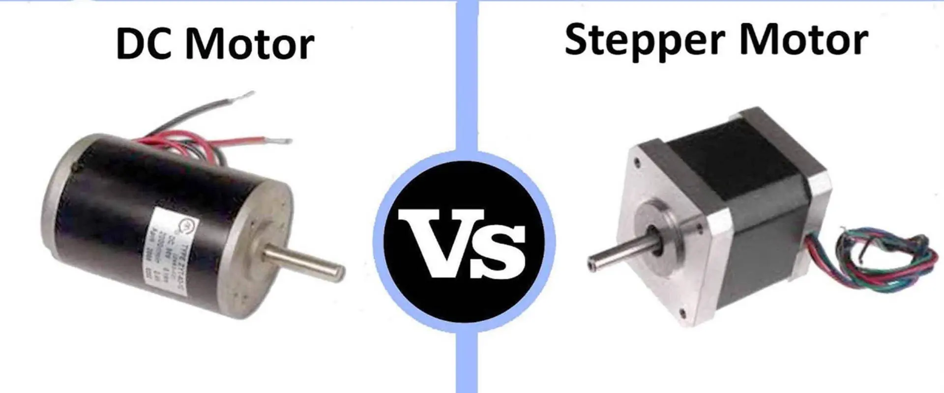
Motors are electro-mechanical devices that convert electrical energy into mechanical energy. They come in a variety of types depending on their construction, working principle, and applications. The two most common types of motors used in industrial and automation applications are servo motors and stepper motors.
Both servo and stepper motors provide precise motion control, but they have some key differences in their design and operation. This article will compare servo and stepper motors in detail in terms of their construction, working principle, performance characteristics, applications, advantages and disadvantages.
Overview of Servo Motors
A servo motor is a rotary or linear actuator that allows for precise control of angular or linear position, velocity and acceleration. It consists of a motor coupled to a sensor for position feedback. It also requires a relatively sophisticated controller, often a dedicated module designed specifically for use with servo motors.
Servo Motor
The key components of a servo motor are:
Motor – Provides the motive force for the actuator. Common motor types used in servo systems include DC brushed, brushless DC, AC induction, and AC synchronous motors.
Gearbox – Used to increase the torque output from the motor. Often equipped with high ratio gears to allow slower motor speeds but higher torque.
Encoder – Sensor that provides position and speed feedback to the controller. Resolvers and optical encoders are commonly used.
Controller – Compares the actual position to the desired position and calculates the required drive signals for the motor. Uses PID control algorithms.
Potentiometer – Measures position of output shaft and provides position feedback to controller.
The controller commands the motor to rotate to the desired position as fast as possible. Once the motor reaches the desired position, it stops. If an external force pushes against the motor, it will hold the position due to the servo control system.
Servo motors provide closed-loop control with high accuracy and fast response times. As a result, they are ideal for applications requiring precise position control such as robotics, CNC machines, pick-and-place equipment, and other factory automation machinery.
A stepper motor is a type of brushless DC electric motor that divides a full rotation into a number of equal steps. Unlike servo motors which rotate continuously, stepper motors move in discrete increments or steps.
Stepper Motor
The key components of a stepper motor are:
Stator – The stationary part consisting of stacked steel laminations with winding coils around the poles.
Rotor – The output shaft along with a magnetized part that interacts with the magnetic field from the stator coils.
Driver – The driver energizes the motor coils in the proper sequence to cause rotation. Open-loop control.
Stepper motors operate on the principle of electromagnetism. The motor coils are energized in a specific sequence, creating magnetic poles that attract and repel the permanent magnets on the rotor. This causes the rotor to turn a precise angle or “step” each time a coil set is energized.
By controlling the sequence and coils energized, the motor can be turned in precise increments. No closed loop feedback is required, though often an encoder can provide position verification.
Stepper motors provide excellent low speed torque and position control without requiring encoders or servo control. They are commonly used in 3D printers, CNC machines, plotters, and other applications requiring high precision motion.
Construction and Design
Both servo and stepper motors have unique construction characteristics optimized for their particular applications and operating principles.
Servo Motor Construction
The construction and design of a servo motor can vary greatly depending on the motor power, torque, speed, and accuracy requirements. But in general servo motors consist of the following components:
Stator – Usually made up of laminated steel with winding coils around the stator poles. The number of pole pairs determines the number of magnetic poles.
Rotor – Made of permanent magnets alternating in polarity around a rotor shaft or core. Often high energy rare earth magnets are used.
Shaft – Heavy duty output shaft with high stiffness for minimal deflection under load. Supported by precision ball bearings.
Housing – Cast iron or steel housing provides structural support and protects internal components. Often thermally conductive to aid cooling.
Feedback device – Resolvers, encoders or potentiometers are attached to monitor rotor position.
Gearbox – High ratio gearboxes are often integrated to increase torque capacity. Spur, planetary, and harmonic gears are commonly used.
The stator, rotor, bearings, and housing make up the actual motor section. The feedback device and gearbox augment the motor capabilities for high performance servo applications.
Stepper Motor Construction
Stepper motors have a relatively simple electromechanical construction optimized for open-loop positioning control. The basic components include:
Stator – Made up of stacked steel laminations with winding coils around the poles. The number of phases determines the number of coil sets.
Rotor – A permanent magnet with alternating north and south poles arranged radially around a central shaft.
Shaft – Usually an integrated shaft machined as part of the rotor. Supported by bushings or ball bearings.
Housing – Lightweight aluminum or thermoplastic housings enclose the stator and rotor. Air or liquid cooling may be integrated.
Bearings – High speed sleeve bearings, bushings or ball bearings support the rotor shaft.
Stepper motors do not require an encoder or gearbox for most applications. The simple stator and rotor design allows rapid manufacturing at low cost.
Comparison of Construction
Comparison
Servo Motor
Stepper Motor
Stator design
Laminated steel with concentrated windings
Stacked laminations with distributed windings
Rotor design
Salient pole or permanent magnet
Permanent magnet
Housing
Heavy cast iron or steel
Light aluminum or plastic
Bearings
High precision ball bearings
Bushings, sleeve or basic ball bearings
Feedback device
Encoder, resolver or potentiometer
Often none, sometimes encoder
Gearbox
Often integral high-ratio gearbox
Rarely used
In summary, servo motors have a robust stator, rotor and housing designed for high torque, speed and continuous duty operation. Stepper motors use lightweight materials and simple construction aimed at low cost and open-loop control.
While both servo and stepper motors produce rotational motion, their internal operating principle and control methods differ significantly.
Servo Motor Working Principle
Servo motors operate on the basis of a closed-loop control system. A controller provides a drive signal to the servo that is proportional to the difference between the commanded position and actual position.
Servo Motor Working Principle
The working principle involves:
An input command to the controller indicating the desired position. This is compared to the position feedback.
Error between actual and desired position is calculated. The controller sends a proportional drive signal to the servo amplifier.
Motor is driven proportionally faster or slower to minimize position error.
Encoder or resolver provides continuous position feedback to complete the control loop.
This closed loop control allows a servo motor to quickly and precisely rotate to a commanded angular position. Servo motors use PID control algorithms to optimize the dynamic response.
Stepper Motor Working Principle
Stepper motors operate on the principle of electromagnetism and discrete stepping of the rotor. Rotation is achieved by energizing coil windings in a specific sequence.
The stepper motor working principle:
Applying current to a motor coil creates an electromagnetic pole. Opposite poles attract, similar poles repel.
Alternating current to the motor coils moves the rotor. As the rotor teeth align with the energized stator pole, they lock in position.
The driver sequentially energizes the motor coils to rotate the rotor in increments or steps. No closed loop control is used.
Step angle is determined by rotor construction. Number of steps per revolution depends on step angle.
The open loop stepping operation allows the motor to move in controlled discrete increments without requiring a position sensor.
Comparison of Working Principles
Comparison
Servo Motor
Stepper Motor
Control method
Closed loop PID control
Open loop stepping
Feedback device
Encoder or resolver
Not required
Accuracy
Very high with closed loop control
Limited by step resolution
Speed
Wide speed range with rapid acceleration
Typically lower speed operation
Torque
High and continuous torque capability
High holding torque, lower power torque
In summary, servo motors use closed loop control for high accuracy while stepper motors operate open loop in discrete steps. Servo systems are more complex but offer better dynamic performance.
Performance Characteristics
The design and operating principles of servo and stepper motors impart distinct performance characteristics.
Servo Motor Performance Metrics
Key performance characteristics of servo motors include:
Speed – Servo motors can operate over a wide speed range, often exceeding 6000 rpm for brushless servo motors. Rapid acceleration and deceleration is possible.
Torque – Servo motors produce high torque, especially at lower speeds. Peak torque ranges from 10 Nm to over 1000 Nm depending on motor size.
Power – Motor output power ranges from under 100 Watts to over 15 kW for large industrial servos. Power density is high.
Accuracy – Position accuracy is very high, reaching 0.01 degree or better with high resolution encoders. Helped by tuned PID control gains.
Repeatability – Positional repeatability is excellent, with consistent positioning under 0.01 degree. Benefits from closed loop control.
High torque density, acceleration, accuracy and repeatability make servo motors well suited for demanding automation applications. Advanced control algorithms allow optimized motion.
Stepper Motor Performance Metrics
The performance characteristics of a stepper motor include:
Speed – Maximum speed ranges from 100 to 2000 RPM. Higher speeds require reduced torque and incremental microstepping.
Torque – Stepper motors have very high holding torque but weaker power torque at higher speeds. Holding torque can exceed 3 Nm for small motors.
Power – Typical motor power output ranges from below 100 Watts up to around 750 Watts. High speed operation results in lower power.
Accuracy – Positioning accuracy depends on stepper resolution. Full step resolution is typically 1.8 degrees. Microstepping divides steps further.
Repeatability – Excellent repeatability thanks to inherent step resolution. Positional error is limited to less than one step.
Stepper motors excel at slow speed, high precision positioning applications. Their relatively simple construction provides robustness at low cost.
Comparison of Performance Metrics
Comparison
Servo Motor
Stepper Motor
Speed range
Very wide, thousands of RPM
Narrow, typically below 2000 RPM
Torque density
Very high
High holding torque, lower running torque
Power output
Up to 15 kW+
Typically below 750 Watts
Accuracy
0.01 degree or better
1.8 degrees full step, higher with microstepping
Repeatability
Excellent, less than 0.01 degree
Very good, limited to step resolution
In summary, servo motors are designed for high speed and power operation with very high accuracy. Steppers trade off speed and power for high precision motion in an open loop control system.
Applications and Uses
The performance characteristics and capabilities of servo and stepper motors make them suitable for different applications.
Servo Motor Applications
Servo motors are designed for high power, high precision motion control applications including:
Industrial robotics – Multi-axis articulated robot arms require high torque servo motors to handle dynamic payloads.
CNC machines – High precision machining relies on fast, accurate servo motor control of linear and rotary axes.
Medical equipment – MRI scanners, CT scanners, and lab automation use servo positioning.
Robotics – Used in cost-sensitive robots requiring modest position control performance.
Stepper motors may not match servos in speed and power, but they provide excellent control in open loop positioning machines.
Comparison of Applications
Comparison
Servo Motor
Stepper Motor
Performance reqs
High speed, power, torque
Modest speed with high precision
Control principle
Closed loop feedback
Open loop stepping
Example apps
CNC machines, robotics, packaging
3D printers, telescopes, medical dispensing
Industries
Manufacturing, robotics, industrial
Manufacturing, medical, aerospace
In summary, servo motors meet the demands of high power, high speed automation applications while steppers excel at slower speed open-loop positioning tasks.
Both servo and stepper motors provide excellent motion control capabilities. But they each have certain advantages and disadvantages to consider.
Servo Motor Pros and Cons
Servo motor advantages include:
Extremely accurate position, speed and acceleration control
High power density and torque-to-inertia ratio
Fast dynamic response and tuning through PID gains
Advanced control capabilities and flexibility
Wide speed range operation
High efficiency
Disadvantages of servo motors:
More complex requiring closed loop control
Higher costs than stepper motors
Requires maintenance of brushes and contacts (for brushed DC servos)
Encoder or resolver feedback device adds cost
Control electronics are complex and expensive
In summary, servo motors provide high performance and flexibility but at higher complexity and costs than alternatives like stepper motors.
Stepper Motor Pros and Cons
Stepper motor advantages:
Excellent position control and repeatability without feedback device
Low cost and simple construction
Open loop control eliminates tuning complexity
Extremely reliable with long service life
High holding torque prevents loss of steps
Available in a wide range of sizes and torque levels
Stepper motor disadvantages:
Lower power and torque during running operation
Limited high speed capability compared to servo motors
Open loop nature limits control accuracy
Can lose steps at high speeds or accelerations
Torque ripple can cause vibrations in some cases
Audible noise during operation
In summary, stepper motors are simple, inexpensive, and reliable, but lack the speed, power, and accuracy of closed loop servo systems.
Comparison of Advantages and Disadvantages
Comparison
Servo Motor
Stepper Motor
Accuracy
Extremely high with encoder feedback
Limited by open loop control
Complexity
High due to closed loop control
Very simple open loop operation
Cost
Expensive; electronics, encoder
Low component cost
Reliability
Brush and contact wear over time
Very reliable and long service life
Speed/power
High speed, power and acceleration
Lower speed and power capabilities
In summary, servo motors provide unmatched performance while stepper motors excel at simple, low-cost, open-loop positioning tasks.
Servo Motors vs. Stepper Motors
Servo Motors
Stepper Motors
Construction
Robust mechanical design, precision gears and bearings, encoders for feedback
Simple lightweight construction, open-loop control
Principle
Closed loop PID control with encoder feedback
Open loop stepping operation without feedback
Performance
High speed and power output, very high accuracy and repeatability
High precision but lower speed and power, modest accuracy
Applications
High performance tasks like CNC machines and robotics
Simpler positioning tasks like 3D printers or telescopes
Advantages
Extreme precision control, fast dynamics, advanced control capabilities
Low cost, simple operation, excellent repeatability, high reliability
Disadvantages
Complexity, high cost, maintenance
Lower power and speed, limited accuracy
Frequently Asked Questions
1. What is the main difference between a servo motor and a stepper motor?
The main difference is that servo motors use closed loop control with position feedback while stepper motors operate open loop without requiring position sensors. This allows servo motors to achieve very precise, high speed control while steppers offer simpler operation at lower speeds and accuracy.
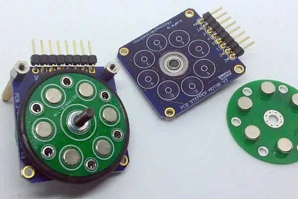
Manufacturing of printed circuit boards makes use of different materials. However, the PCB laminates are known as the main raw materials that are useful in the fabrication of printed circuit boards
Here’s another focus on the Arlon PCB Material. This time, we will be focusing on the Arlon 51N PCB Material. In this article, we will be discussing why this material has high reliability and why it is very useful in rigid-flex complex fabrication.
If you wish to gain much knowledge concerning the Arlon 51N PCB Material, please continue reading as we take you through different aspects of the topic.
The Arlon 51N PCB Material is a multifunctional non-DICY epoxy prepreg system which came to be to offer high reliability via solder operations that are lead free.
The thermal stability and high decomposition of the Arlon 51N PCB Material is great for use in rigid-flex complex fabrication, as well as assembly operations whereby there is a need for minimum resin flow.
Furthermore, this material possesses great mechanical and electrical properties that meet the IPC-4101/126 prepreg requirements.
What are the Features of the Arlon 51N PCB Material?
The Arlon 51N PCB Material has a decomposition temperature that is higher than 350 degrees Celsius and it is great for solder processing that is lead free. It also provides great improvement over the traditional Epoxy FR-4 systems.
This resin system is multifunctional. Also, it has a temperature for glass transition of 170 degrees Celsius for optimal PTH reliability. Also, the bond adhesion is improved over many thermal excursions. This leads to better reliability via rework and reflow operations.
Furthermore, it is RoHS/WEEE compliant and it is compatible with any solder processing that is free of lead. In addition, the mechanical and electrical properties meets the IPC-4101/126 prepreg requirements, which is modified to become “low-flow”
In addition, for any epoxy system, this material has the best thermal performance. At T260, it os greater than 60 minutes, at T280, it is greater than 30 minutes, and at T300, it is 15 minutes.
Typical Applications of the Arlon 51N PCB Material
These are areas where you can apply the Arlon 51N PCB Material
Dielectric insulators
The Arlon 51N PCB Material is useful in dielectric insulators, because they can serve as insulators. It makes it possible for these dielectric insulators to refuse the flow of electric current.
Completed PCB assemblies that requires great thermal stability
As mentioned earlier, the Arlon 51N PCB Material has great thermal stability. This is why it is very useful in PCB assembly because they offer excellent thermal stability to the finished PCB.
Applications requiring uniform or minimal resin flow
The Arlon 51N PCB Material is also very useful in any application that requires a uniform or minimal resin flow.
What are the Properties of the Arlon 51N PCB Material?
The Arlon 51N PCB Material has some reliable properties that ensure its high reliability and performance. Let’s consider them.
Physical Properties
The Arlon 51N PCB Material has the following physical properties. It has a flammability rating of V0 as well as a thermal conductivity of 0.25 W/mk. Furthermore, it has a density of about 1.65 g/cm3, as well as a water absorption value of 0.15%
Thermal Properties
The Arlon 51N PCB Material has the following thermal properties. Its temperature for glass transition is 170 degrees Celsius.
Also, its decomposition temperature is 354 degrees Celsius at the initial. Then at a weight loss of 5%, the value becomes 368 degrees Celsius. At 50 – 260 degrees Celsius, the Arlon 51N PCB Material’s expansion along the Z-axis is 2.6%.
For the X, Y axis it has a coefficient of thermal expansion (CTE) of 15 ppm/C. At T260, it is higher than 60 minutes, while for T288, it takes more than 30 minutes. Then for T300, the value is 15 minutes.
Electrical Properties
The Arlon 51N PCB Material has the following electrical properties. Its dielectric constant is 4.2 at 1 MHz, while at 1 GHz, the dielectric constant is 4.1.
Also, it has a volume resistivity of 2.6 × 10⁷ MΩ-cm for C96/35/90, while at E24/125, it has a volume resistivity of 3.3 × 10⁷ MΩ-cm. Also, at 1 MHz, it has a dissipation factor of 0.02.
Furthermore, this PCB material has an electrical strength of 39.4 kV/mm and an arc resistance that is greater than 124 seconds. Its surface resistivity at E24/125 and C96/35/90 is 4.0 × 10⁶ MΩ and 2.9 × 10⁷ MΩ respectively
Mechanical Properties
The Arlon 51N PCB Material has the following mechanical properties. Its Poisson’s Ratio is 6.5 and its young’s modulus for CD/MD is 2.6 Mpsi or 18 GPa.
In addition, its peel strength with respect to copper is 1.2 N/mm after thermal stress. Then at elevated temperatures, it stands at 1.2 N/mm, while after process solutions, the value is 1.1 N/mm. Also, the tensile strength is 578 Mpa or 84 kpsi.
What are the Recommended Conditions for Processing the Arlon 51N PCB Material?
First make sure that the inner-layers are processed through strip, etch, and develop making use of the normal industry practices. Furthermore, bake the inner layers using a rack at a temperature falling within 225 degrees Fahrenheit and 250 degrees Fahrenheit.
This should be done before lay-up. Also, make sure that you vacuum desiccate your prepreg for about 8 to 12 hours before you laminate.
Lamination Cycle of the Arlon 51N PCB Material
The lamination cycle of this material is as follows
Pre-vacuum for about 30 to 45 minutes
The rise in heat has to be controlled to about 8 degrees Fahrenheit to 12 degrees Fahrenheit every minutes
Lamination pressure has to be between 150 to 300 PSI. Note that thus depends on complexity
Also, the temperature of the product at the beginning of the cure should be 360 degrees Fahrenheit.
Cure time at the temperature is 90 minutes
Conclusion
This article has explained everything you need to know about Arlon 51N. This PCB material offers a lot of benefits and features.
You no longer must worry about the complexity of electronics circuit boards. With the Taconic RF-35TC PCB, installations become a breeze, and you can focus on the things that matter. This board’s design can handle high-voltage and high-frequency output requirements at a low noise level. It is also compatible with any standard or custom application, making it simple to connect to whatever else you need in your project.
The Taconic RF-35TC PCB delivers all you need for an installation. Its high-quality, robust design is ideal for use in various applications. The manufacturers such as RayMing PCB and Assembly design it specifically for outdoor use and under extreme conditions. The Taconic RF-35TC PCB can withstand temperatures as high as 70 degrees Celsius. Moreover, it has a unique, tempered glass fiber insulation that is resistant to moisture and corrosion. The result is always better performance and with minimal maintenance.
In addition to this, the Taconic RF-35TC PCB uses a copper ground plane. Therefore, it has an excellent optimization for electricity. With its ability to improve overall performance, this is an ideal replacement for other boards in your system.
The Taconic RF-35TC PCB consists of high-quality materials and can endure a wide range of temperatures. It is suitable for outdoor or indoor use and its design is suitable for tough conditions. It makes it an ideal part of your projects. Its primary material is epoxy glass with high thermal shock resistance and great flexibility. Thanks to this, the Taconic RF-35TC PCB can withstand excessive heat and cold at the same time. It will still maintain excellent performance over time.
The second material used in the Taconic RF-35TC PCB is copper foil. It is a highly conductive material that can withstand high voltages and frequencies. Beyond this, the copper foil also has excellent electrical conductivity. As a result, it makes this board an ideal replacement for other boards in your system.
Specifications:
The Taconic RF-35TC PCB has a variety of specifications depending on how you want to use it. Its high-quality brass connection blocks make it suitable for use in a wide range of applications. At the same time, its copper ground plane can help improve the overall performance of your installation.
Compatibility:
The Taconic RF-35TC PCB is compatible with any standard or custom application. We can use it with most other components you might have in your system. This means that it is easy to use with many other components simultaneously. It also has a low noise level, which we can connect to many other components without causing interference.
Operating Temperature:
The Taconic RF-35TC PCB can withstand a wide range of temperatures, including temperatures as high as 70 degrees Celsius. Without problems, it can handle conditions that maintain high-voltage and high-frequency output simultaneously. Moreover, this makes the board suitable for use in any situation.
Terminations:
The Taconic RF-35TC PCB uses various types of terminations depending on your needs. Its high-quality connections are weatherproof, and we can use them in a wide range of conditions without problems. From its ground block connectors to its phone port, the Taconic RF-35TC PCB is ideal for any other board you might have.
The Taconic RF-35TC PCB is a two-layer board. This means it is very simple to use, especially as you do not need to make extensive modifications to work with the Taconic RF-35TC PCB. This makes the board very easy to install and enables smooth connections between various components.
The first layer of the Taconic RF-35TC PCB contains all of the components on the board, including resistors, capacitors, relays, and more. Each of these components has a connection to the next layer through copper tracks. The second layer contains all the board’s connections, such as its ports and phone connectors.
3. Connectors
The Taconic RF-35TC PCB features various connectors to make it compatible with almost any type of application. Its high-quality brass connection blocks are suitable for use in any situation and are very easy to work with. In addition, each connector has a low-key connection that can withstand the use of high-voltage and high-frequency signals. This ensures good performance through your system.
The Taconic RF-35TC PCB uses various types of connectors depending on your needs. Its phone connector is weatherproof and is suitable for use in any situation. So, we can use its ports for any other applications you might have in mind.
4. Thickness
The Taconic RF-35TC PCB has a thickness of 0.8 millimeters, making it an ideal component for use in any project. Furthermore, as it is so thin, the board takes up little space. Therefore, we can easily connect it to other components without taking up much room. This also makes the Taconic RF-35TC PCB suitable for use in tight areas.
5. Size
The Taconic RF-35TC PCB measures 2.2 by 2.2 by 3.2 inches and weighs 1 pound, making it an ideal component for use in any of your projects. It is also very easy to install and install in areas with a wide range of sizes and shapes. Its thin design means we can install it in tight spaces without problems.
6. PCB Usage
The Taconic RF-35TC PCB is compatible with most applications thanks to its versatile and ergonomic design. We can use it with a wide range of projects. It includes component upgrades and network designs. Its excellent performance makes it ideal for use in any installation.
7. Surface finish
The Taconic RF-35TC PCB has a matte blue finish that makes it suitable for use in any installation. This finish helps prevent oxidation and other damage to the board. At the same time, it will still providing excellent performance in your system.
8. Soldering pads and holes
The Taconic RF-35TC PCB has a range of different soldering pads to make it compatible with most applications. It is suitable for use in any installation and can withstand a wide range of temperatures. At the same time, its soldering pads are very free from oxidation and other problems, making it an ideal component for use in your projects.
The Taconic RF-35TC PCB has an excellent design for many applications, so it is good for most projects. Here are some benefits that you can get from using the Taconic RF-35TC PCB.
1. Quality design:
The Taconic RF-35TC PCB has a good design that makes it user-friendly and straightforward as possible. This makes ii maintain high performance. This means it is easy to use and install while still providing excellent performance in your system over time.
2. Connectivity:
The Taconic RF-35TC PCB is easy to use and install while maintaining high performance throughout your installation. Due to this, the Taconic RF-35TC PCB is a good choice for almost any type of project. It also has a low noise level. This means we can connect it to other components without causing interference.
3. Excellent adhesion to Very Low Profile Copper:
The Taconic RF-35TC PCB has a low profile that can work with very low hole patterns. This means it is compatible with almost all applications while still maintaining high performance.
4. Enhanced antenna gains/efficiencies:
The Taconic RF-35TC PCB has a wide range of high-quality terminations designed to be weatherproof. This means we an use them in any environment. Furthermore, it makes them an ideal component for use in any installation.
5. DK Stability across a broad temperature range:
Thanks to its low noise levels and excellent performance, we can use the Taconic RF-35TC PCB in almost any application. This also ensures that you will get the best performance out of the board without experiencing any problems with your system.
6. Exceptional thermal management:
The Taconic RF-35TC PCB is compatible with a wide range of applications. This means it is suitable for use in any situation while still maintaining high-performance thanks to its excellent thermal management abilities.
7. “Best in Class” loss tangent:
The Taconic RF-35TC PCB can maintain a low noise level at low frequencies. This helps it maintain excellent performance in any installation, while its loss tangent is one of the best in the industry.
Taconic RF-35TC PCB is suitable for use in many applications, including network and system upgrades. Here are some common applications that you can use the component with.
1. Encryption/Decryption:
The Taconic RF-35TC PCB designed can provide excellent performance in any system. Moreover, it does not cause problems for any other components. This means it is a good choice for use in any situation, such as installing new telecommunications equipment.
2. Wireless LAN:
The Taconic RF-35TC PCB has an excellent design that we can use in any wireless LAN system. It has a low noise level. As a result, we can easily connect it to other components without causing interference. This offers a wide range of benefits for your installation.
3. Computer peripherals:
The Taconic RF-35TC PCB is a good choice for use in almost any system, making it an ideal component for use in your computer accessories. In addition, its design is compatible with a wide range of applications, making it suitable for most projects.
4. Radiofrequency equipment:
The Taconic RF-35TC PCB is an excellent choice for use in many types of radiofrequency equipment. It includes microwave equipment and other similar devices. Its design can maintain a low noise level while still providing excellent performance over time.
Conclusion
If you have a keen interest in the Taconic RF-35TC PCB, we strongly recommend buying it from Amazon. It is a high-quality board that has everything you need for your project in one place. Moreover, the board is compatible with many other components, and we can use it with almost any application.
The next time you have an idea for a project in mind, look at the Taconic RF35TC PCB to get started on your next project. It is a high-quality component that has everything you need in one convenient package. It makes it an ideal component for use in almost any situation.
Arlon has continued to deliver high-performance laminates for various PCB applications. Laminate and prepreg are core materials for PCB fabrication. However, it is crucial to use high-quality materials for PCB fabrication. Therefore, the Arlon 44N was specially formulated to deliver great quality and performance. In this article, we will look into one of Arlon’s best quality materials, Arlon 44N.
What is Arlon 44N PCB Material?
Arlon 44N PCB material is a multifunctional micro dispersed epoxy prepreg system. This material is filled with epoxy fiberglass. Also, this PCB material features high resin content. Arlon 44N PCB material was specially designed for filling up clearance holes in thin metal PCBs. For example, it can fill clearance holes in 0.006 inches Copper-invar-Copper. Also, it is ideal for via holes in sequentially laminated multilayer board designs.
This prepreg system is very compatible with conventional epoxy fabrication. Arlon 44N PCB material reduces cracking and resin shrinkage in filled clearance holes. Also, the prepreg format removes any need for messy paste fill material. This material features a high Tg value that is very compatible with multifunctional epoxy processing.
Furthermore, Arlon 44N PCB material is available in high resin content prepreg. This material meets the specifications and requirements for IPC 4101/98. Therefore, it is a very reliable prepreg system. Also, Arlon 44N features great mechanical, electrical, and thermal properties.
The glass transition temperature of Arlon 44N is 175 degrees Celsius. This is a high Tg value. Therefore, this material offers thermal stability. The Tg value is the same at DSC and TMA.
The Z-axis CTE value of Arlon 44N is 55 ppmo/C before glass transition temperature. After Tg, the CTE is 200 ppmo/C. However, the CTE at X and Y-axis is within the range of 14 – 16 ppmo/C. These values are ideal for PCB materials.
Mechanical properties
The peel strength is 8 Ib/in (N/mm) at elevated temperature and after thermal stress. Also, this value is the same after process solutions.
The water absorption rate of Arlon 44N is very low. This material features a 0.1% water absorption rate. Therefore, this material is ideal for use in a very humid environment.
The young’s modulus is 2.8 Mpsi (GPa). Also, this mechanical property determines the functionality of this material. Therefore, it is very important.
The dissipation factor of Arlon 44N is 0.025 at 1 MHz. Also, this is a very low dissipation factor. This indicates that it has a good insulator system.
The volume resistivity of Arlon 44N at C96/35/90 is 2.6 x 10⁷ ohm-cm. This value of this property becomes 3.3 x10⁷ ohm-cm at E24/125.
Arlon 44N is a PCB material that features no lead components. Therefore, this material is ideal for use in lead-free applications.
Multifunctional epoxy processing compatibility
This material is very compatible with the processing of conventional multifunctional epoxy. This is due to its high Tg value.
Industry approvals
Arlon 44N PCB material is recognized and approved by some standards. For instance, this material complies with RoHS/WEEE standards. Also it meets the requirements and specifications of UL 94 V-0. In addition, it meets the specifications of IPC 4101/98.
Reduction of resin shrinkage
Arlon 44N is filled with micro-disperse ceramic. This helps to reduce cracking in filled clearance holes. Also, it reduces resin shrinkage.
Processing Conditions for Arlon 44N PCB Material
Experts recommend using vacuum assist lamination or vacuum for processing this material. Time, pressure, and temperature will depend on the panel size and other factors. Regulating the rate of heat-up is very important. The temperature of the multilayer package should be about 4-7 degrees per Celsius.
You should use a 90 minute cure temperature of 185 degrees Celsius to achieve a glass transition temperature below 170 degrees Celsius. You may need to extend the cure time to offset the metal’s heat lagging effects.
Use 1 hour for the first lamination in a sequential lamination. Then, you can now use 90 minutes for the final lamination. The cool down under pressure should be less than 5.5 degrees Celsius per minute. You can increase reliability cracking resistance by cooling down at less than 3 degrees Celsius per minute.
You should drill at 350 square feet meters. Experts recommend an undercut bit for vias that are 0.45cm and smaller. Utilize alkaline permanganate to desmear. Also, you can use plasma desmear with settings ideal for FR-4. For HASL or solder reflow, bake PCB for 1-2 hours at 121 degrees Celsius.
Arlon 44N PCB material is ideal for use in some applications. This PCB material features some properties that make it suitable for these applications.
Filling thick metal copper ground planes
Arlon 44N PCB material is specifically designed to fill up clearance holes. This prepreg system is ideal for filling up thick metal copper ground planes.
This PCB material is widely used for BGA packaging. BGA packages help to mount devices like microprocessors. Also, these packages can offer more interconnection pins than you can put on a flat package.
Arlon 44N is a core material in automotive under-hoods. Also, this material meets the increasing need for fuel efficiency and high performance. Wire toughs and battery boxes are examples of under-hood applications.
This is another application that relies on Arlon 44N PCB material. Also, this material meets the requirements of high layer count multilayer boards. It is thermally stable and reliable.
Backplanes and mother boards
Arlon 44N plays a crucial role in designing backplanes and motherboards. Backplanes function almost the same way as motherboards. Backplanes and motherboards are printed circuit board that feature connection slots for boards’ expansion. Also, this PCB enables communication between connected boards.
Conclusion
Arlon 44N PCB material is a core material for fabricating PCBs. Also, this material meets PCB industry standards. Therefore, it is highly reliable and safe for PCB fabrication.
Nelcote V-376C Cyanate Ester Epoxy Prepregs and 7781E + AS4A E-Glass reinforcement are prepregs or fabrics. As a result, we use them with a BPO/BMS resin system. So, these composites help demand airframe applications. So, they require good heat resistance and high performance.
Nelcote V-376C Cyanate Ester Epoxy Prepregs offer an epoxy-based adhesive bond strength of approximately 50 MPa. Additionally, they also offer a unidirectional tensile strength of approximately 38 MPa. Combined with the resin system’s heat resistance and good mechanical properties, these materials are ideal for applications where we need a high-temperature cure.
Nelcote V-376C Cyanate Ester Epoxy Base Resins are thermosetting resins. They cure at elevated temperatures and show broad temperature resistance. Nelcote V-376C Cyanate Ester Epoxy Base Resins are highly resistant to moisture, water vapor, alcohols, acids, and most organic solvents. Additionally, they have good chemical resistance. This includes aromatic solvents, oils, greases, and many food products.
1). A solvent dissolving resin system that provides good adhesion to and bonding with various materials. They include low-temperature plastic and rubber,
2). An epoxy resin/hardener combination provides excellent tensile and impact strength.
Additionally, the 7781 EB resin system is also compatible with other polyester-based polycarbonate resins such as 3 M’s Rocol and Eskimo. In addition, the 7781 + AS4A E-Glass reinforcement system can also be helpful in the fabrication of composite parts where the heat of repair requirement is high.
3). A high wet out of fabric with no need for “backing” with a release agent and
4). An excellent dielectric strength of 2500 V/mil.
The Nelcote V-376C Cyanate Ester Epoxy Prepregs is suitable for use with the 7781 EB resin system. The 7781 EB resin system is a modified butyl rubber-based epoxy binder. As a result, it allows general-purpose resins to fabric fiberglass-reinforced prepregs and composite parts. In addition, the 7781 EB resin system utilizes chlorinated butamides to lower the viscosity. Therefore, it enables the impregnating of more epoxy and more resin into the fiberglass fabric.
The Nelcote V-376C Cyanate Ester Epoxy Prepregs are suitable for use with the 7781 EB resin system. Additionally, other composite materials, such as ABS and polycarbonate, may also be helpful with the Nelcote V-376C Cyanate Ester Epoxy Prepregs.
V-376C Cyanate Ester Epoxy Prepregs come in widths up to 122 inches (3.15 m) and lengths up to 200 inches (5.08 m).
Physical Properties:
1). Thickness, nominal, 0.020″ to 0.250″; Specific Gravity, 1.89 ± 0.05;
2). Water Absorption, 24 hours at 23°C (73°F), by weight, ASTM D570
3). Ultimate Tensile Strength at Break and Elongation at Break of Fabric in 8” (20 cm) wide specimens as Tensile Strength, 35%, ±5%;
4). Compressive Stress-at Break, 40% of Specimen width, ±3%; and
5). Apparent Density (Air = 1), g/cm3 at 25°C (77°F), 915 to 945; and a Specific Gravity of 1.895 to 1.915.
Adhesive Properties:
The resin-epoxy adhesive on Nelcote V-376C Cyanate Ester Epoxy Prepregs provides a bond strength of approximately 50 MPa. They also offer a unidirectional tensile strength of approximately 38 MPa.
Tensile Testing:
Tensile testing (ASTM D638B Method A) happened on 2”× 2” samples of the fabric in tension at room temperature (23°C ±2°C).
Stripping:
We test the stripping characteristics of the V-376C Cyanate Ester Epoxy Prepregs by placing a 20 gm sample of prepreg in a glass jar. Then, we added distilled water and measured weight after 24 hours at 23°C ±2°C. We do not add any solvent to the water.
Adhesion Testing:
We test the adhesion strength of the V-376C Cyanate Ester Epoxy Prepregs by applying ten gms/sq. The prepreg-inch to a steel plate and heat curing at 160°C in an oven for 30 minutes.
Functionality Testing:
Then we conduct functionality testing on the V-376C Cyanate Ester Epoxy Prepregs. We measure dielectric strength, tensile strength, and compression test results.
The variable thicknesses and composition of the fibers in the high-performance BPO/BSS system added flexibility to design alternatives that they could now incorporate into airframe designs.
Then they evaluate three different BPO/BSS resin systems in airframe applications. Additionally, Rayming PCB & Assembly test the first system in a simple, one-piece foam sandwich structure and a two-piece foam sandwich structure.
Secondly, they test the second BPO/BSS system in a one-piece carbon-fiber sandwich structure that incorporated some Nelcote V-376C Cyanate Ester Epoxy Prepregs. Finally, they compare this sandwich
The third BPO/BSS system helped test Nelcote V-376C Cyanate Ester Epoxy Prepregs in an airframe prototype deployed as a “drone.” As a result, we build this prototype with a carbon fiber/epoxy sandwich. They use a Nelcote V-376C Cyanate Ester Epoxy Prepregs in the airframe and the fuselage.
The final prototype, built with BPO/BSS resin systems, had more than 350 pounds (160 kg) and a wingspan of 41.5 feet (12 m). This airframe was also the first to incorporate a one-piece integral air intake duct and an integral, heavily modified Pratt & Whitney JT8D engine.
As with the previous BPO/BSS applications, a five-layer laminate was helpful. The first four layers were fiberglass/epoxy and comprised the pre-engineered structure. We applied the final layer over the engine in a glass/epoxy matrix to dissipate heat from the engine.
The prototype was subject to various testing and evaluation procedures. It includes static and dynamic tests, oil/gas/vapor diffusion testing, LCA studies, and thermal fatigue testing. This testing revealed that the structural integrity of the BPO/BSS airframe design was excellent, with no unexpected failures.
Advantages of BPO/BSS Systems
Using the BPO/BSS system significantly decreased the cost of manufacturing these resulting aircraft. The cost of labor was also considerably reduced. In addition, BPO/BSS did not generate any hazardous waste and could safely work using standard shop tools and skills.
Disadvantages of BPO/BSS Systems:
BPO/BSS systems also had structural limitations, such as poor resistance to crush and vibration. In addition, this application-specific batch design influences the mechanical properties of the resin and fiber. For example, it creates a thermal mismatch between the epoxy and fiberglass layers. However, it presented problems with heat dissipation during flight.
They constructed the simple sandwich design from a 3” “T” shaped fiberglass backplate attached to a 4” × 2” × .125” (10 × five × 3 mm) layer of 1.25 lb/ft2 (86 g/m) BPO-31 epoxy. The laminate was then bonded (I-beam style tooling) onto a backplate. Finally, they bonded the upper portion of the sandwich to a 1” round fiberglass nosecone. They used this BPO/BSS system as a prototype for a mid-size aircraft.
Nelcote V-376 Cyanate Ester Epoxy Prepregs, 7781 E-Glass Reinforced Epoxy Resins, and the BPO/BSS System have met or exceeded all testing and performance requirements aircraft, aerospace, defense, and industrial applications.
The durability of the V-376C Cyanate Ester Epoxy Prepreg remained intact. After exposure to an oil/gas/vapor test, it has no significant degradation. A fuel surrogate was helpful in this test because its results are like those of jet fuel.
The Nelcote 7781 E-Glass Reinforced Epoxy Resins performed as expected in all LCA studies. In addition, it did not produce any negative effects.
The end-user was extremely satisfied with the performance of Nelcote V-376C and the BPO/BSS system. This airframe prototype incorporated a one-piece carbon-fiber sandwich. It was a unique construction in aircraft design at that time, and it performed flawlessly.