Schweizer PCB is a company managed by a family and based in the Black Forest region of Germany – Schramberg. Also, you will find it listed in your Frankfurt and Stuttgart stock exchanges. If you are searching for a PCB custom manufacturer to meet the requirements in majority of different markets and sectors, then Schweizer PCB must be included.
Their PCB technologies are useful in some demanding applications such as the industrial, aviation, automotive, computing, communication and medical sectors. The leading companies in these sectors globally relies on Schweizer PCB’s vast experience, innovative force, as well as excellent service and product quality for embedding and PCB solutions. Also, the technologies of Schweizer PCB also have great environmental properties and an impressive energy.
A big thanks to their ultra-modern sites for PCB production in the Schramberg, as well as Jintan in China, coupled with their close partnerships as well as other strong technological innovators, Schweizer PCB will be able to provide you with global access to their high-quality PCB. This ranges from the customer-specific designs to the standard solutions. Regarding the size, as well as other needs, Schweizer PCB has got you covered. They also offer high cost effectiveness.
As we already explained, Schweizer is known as one of the top PCB manufacturers in our automotive sector. However, there is more to this. The company has also made a great name in other sectors globally as a result of their high-end embedding solutions and PCBs.
Automotive
Schweizer PCBs are useful in numerous applications of the top automotive manufacturers. They provide the technological basis to ensure autonomous and safe driving. Also, you can find them in gearboxes, steering systems, fans, electric motors, as well as heating systems. Furthermore, they are useful in the system for driver assistance like distance control systems as well as lane and braking control systems.
The end devices include radar applications (LiDAR, parking and distance assistants), steering systems, starter generators, inverters used for different 48V applications, camera systems, LED lighting, wall boxes, and battery management.
The challenges here include the support for different projects from prototype and to the series production. Another is the close cooperation with the Tier 1 departments for development. Understanding the present mega-trends (autonomous driving, CO2 reduction, and electrification). Others include reliability, quality, and application understanding
Aviation
The solutions of Schweizer PCB ensure safety and switching functions for the primary as well as secondary systems like SSPCs (solid state power modules) as well as RPDUs (remote power distribution units). Furthermore, these are useful in the future technologies like drones and air taxis.
All thanks to the quality management and Nadcap accreditation, you can be sure of top quality, safety, and reliability.
The end devices include safety and switching functions for secondary and primary systems, the SSPCs (solid state power modules), RPDUs (remote power distribution units), infotainment/multimedia systems, interior lighting, cabin control and communication systems.
The challenges here include the EN9001 certification and Nadcap required, the high quality levels as well as the necessary process reliability. Others include application understanding, reliability, and quality.
Increasingly, the technologies of Schweizer PCB are also useful in the industry 4.0 and industrial applications. Furthermore, from the position sensors present in the sector of wind power to the battery switches as well as the track monitoring systems, point level sensors, and the automated door opening mechanism, you can be sure that anything can happen.
Currently, in the technology and medical sector, the Schweizer PCBs are very useful in the intensive and emergency care devices, monitoring displays, diagnostic units, and mobile appliances. The end devices include machine tools, point level sensor, robotics, electric razors, angle and distance sensors, electro-medical mobile devices, as well as warehouse handling.
The challenges here include industry 4.0, the product portfolio that ranges from the two sided boards to more complex HDI circuit boards.
Computing and Communication
Excluding the powerful and strong HF technologies, you cannot imagine different concepts like industrial 5G, mobile communication 5G, autonomous driving, augmented reality, as well as Industry 4.0, talk more of it even happening.
Regarding the automotive sector’s extensive expertise, Schweizer PCB provides PCB solutions for the networked and automated control, as well as monitoring vehicles, plants, machines, as well as other complex systems.
The end devices here include logic controllers, server applications, 5G, and camera monitoring systems. The challenges here include base materials like Teflon, which helps in creating the fine structures of the conductor, as well as high reliability and high temperatures.
Why Choose Schweizer PCB for Your PCB Technologies Solutions
The following are the reasons why you should choose Schweizer PCB.
They serve as a solution space
Schweizer PCB provides a wide range of solutions and technologies, which meets very high requirements. These services include complex high current, 2-layer circuits, radar lay-ups, etc. This is possible through their standard processes, which has given them the opportunity to react to client’s inquiries, as well as integrate their requirements flexibly and quickly.
In addition, for the complex issues, they have an expert team which offers competent advice, as well as develop some solutions. They are there with you all through the process, from the initial stages and idea to the high-volume production. They are also there for each technical requirement and high cost-effectiveness.
The Schweizer Technology is Reliable
Whether you need complex or simple multilayerHDI PCBs, heavy copper designs specially for your power electronics, Inlay Boards, hybrid as well as fine structure lay-ups of your radar applications, as well as embedding solutions having power semiconductors, you’ll get it from Schweizer. This is because they offer custom developments in order to help in solving your problems as well as meet all the necessary and specific requirements.
Shapes the future actively
The global success of Schweizer PCB is based on their extensive research as well as development. They have an innovation center located at Schramberg. Here, they develop PCB technologies, which derives their top system solutions for issues from mega-trends. Also, Schweizer PCB teams up with top research institutes, industrial partners, and universities.
Conclusion
Schweizer PCB is surely one of the top PCB manufacturers globally due to their innovative technologies and research.
With the dynamic changes in electric circuit fabrication, the application of more developed electronic components is essential. For example, fabricating such complex switches as appliance printed circuit boards (PCBs) may involve expensive components. It is, therefore, necessary to take great care of these components by protecting them from damage at all costs. The presence of a fuse in the circuit solves the equation. However, going for quality and reliable fuses might be necessary when incorporating fuses into our setups. SMD fuses are one of the world’s most reliable types of fuses. However, you must get the best SMD fuses for application in your design work. Therefore, it would be best if you went for fuses from the best manufacturers. The following are the top 8 best SMD manufacturers in the world.
Founded in 1927, Littelfuse is one of the most popular manufacturers and distributors of SMD fuses. The company aims to achieve an empowered, sustainable and connected world. Littelfuse is headquartered in Illinois, Chicago, United States of America. In addition, the company has established other operation points in more than 15 countries worldwide. Moreover, Littelfuse has established good partnerships with more than 17,000 global associates.
Additionally, the company serves more than 100,000 end clients worldwide. In addition, the company has more than 20 operational research labs worldwide. With its large-scale production of SMD fuses, the company produces effective circuit protection solutions for its end customers. To ensure the durability of their products, Littelfuse offers prior electronic testing services to their customers before the shipment of the product.
Products
Other than SMD fuses, Littelfuse is a famous dealer in other electronic products such as:
The company’s products are applied in such fields as:
Automotive Connection
Building automation
EV charging
General port protection
Medical technology
LED lamps protection
Consumer computing designs
Certification
Littelfuse can boast such certifications as ISO9001 Quality management system, ISO14001 Environmental management system, and ABS PGR-8800.
Market
The company has many end customers and a solid global market in all its operation points. In 2021, Littelfuse recorded net annual sales of approximately 2.08 billion US dollars.
Founded in 1996, CYG Wayon, also known as Wayon Electronics, is a famous SMD fuse manufacturing company headquartered in Shanghai, China. Additionally, the company has well-established operation points in other regions such as South Asia and Europe. In addition, the company hosts over 490 employees worldwide. Moreover, the company has an additional over 100 talented FAE, R&D, and technical support staff. On top of that, Wayon electronics owns over 200 Intellectual Properties and Patents.
Products
Other than SMD fuses, the company deals with other electronic components such as:
Wayon electronics holds the following certifications:
ISO9001 Quality Management System
ISO14001 Environmental Management System
IATF16949 Product certification
Moreover, the company’s SMD fuses are approved by such quality bodies as TUV, UL, and AEC-Q.
Market
The company is a global provider of circuit protection solutions and has a solid international market. Its certifications and approvals aid in boosting both the domestic and global product market.
Founded in 1947, Bourns is an electronics manufacturing company that, in its work, fabricates SMD fuses. The company is headquartered in Riverside, California, USA. Additionally, Bourns is a privately owned company. It is named after Marlan and Rosemary Bourns, who are its founders. Moreover, Bourns company hosts over 9000 talented employees. Since its establishment, the company has established over 15 research labs and over 500 operation points worldwide. In addition, the company has a well-set satellite office in Santa Clara, California, USA.
Products
Apart from SMD fuses, the company also has a specialty in the manufacture of the following electronic components:
The company’s facilities are certified to ISO/TS16949:2002 and ISO9001:2000. Additionally, Bourns is seeking the TL9000 certification for telecommunications industry-related products.
Market
Owing to a large number of operation points, Bourns has a solid global market. Moreover, the various research labs facilitate continuous research, equipping the researchers with up-to-date skills. Consequently, their products are of high quality, granting them a competitive advantage over other similar companies.
Hollyland group was founded in 1975. With 47 years of experience, the company has become one of the leading circuitry protection manufacturers worldwide. The company is a famous manufacturer and distributor of SMD fuses in China, the Middle East, and the world. Hollyland’s headquarters are in Asia-Pacific (APAC) region, in Beijing, China. Hollyland group is well known throughout its operation period for its high-quality SMD fuses. The company hosts approximately 1000 talented employees.
Products
Besides SMD fuses, the company also deals in other electronic components such as:
Axial lead fuses
Radial lead fuses
Low voltage fuses
New energy special fuse
Surface mount fuse etc.
Application of Products
Hollyland’s SMD fuses have a wide range of applications in fields such as:
In 1998, the company was accorded the ISO9001 quality system certification by BSI. Additionally, in 2001, the Hollyland group was awarded the automotive quality system certification, ISO/TS16949:2009. Moreover, the company’s products are RoHS accredited and lead-free compliant.
Market
Hollyland company has a stable domestic market in the Asia-Pacific (APAC). In addition, the company has a solid online marketing platform that allows for a global market network. Moreover, the company serves over 100,000 end customers in China and Asia.
Founded on June 17th, 1993, KOA electronics is a popular SMD fuses worldwide manufacturer. Additionally, the company undertakes the distributing task of its components across the globe. KOA Electronics is headquartered in Metropolis Drive, Hunghom, Kowloon, Hong Kong. In addition, KOA electronics company is a large-scale manufacturer with a working capital estimated at 1,500,000 US dollars. Moreover, the company hosts over 1000 employees, with over 100 staff members.
Products
Other than SMD fuses, the company has a specialty in the manufacture and distribution of the following products:
SMD resistors
Varistors
Inductors
Thermal sensors
Thermistors
Leaded resistors
Current shunt resistors
Hybrid ICS
Check terminals
Charge controllers etc.
Application of Products
KOA electronics’ products are applied in the following fields:
In the course of its operation, the company has the following certifications:
ISO9001:2015 quality management system
IATF16949:2016 product certification
ISO14001 Environmental Management System
Market
Since KOA Electronics (HK) Limited is a wholesale distributor of SMD fuses, it has a well-established domestic market in the Asia-Pacific (APAC). Additionally, the company can brag about a solid global market resulting from many end customers in over 70 countries. Consequently, the company distributes its products globally via air and water shipment. Moreover, the company has an online marketing platform, making its products easily accessible from all corners of the world.
Founded in 1933, Schurter group is a Swiss family-owned electronic company. In addition, the company deals in the fabrication and distribution of SMD fuses, besides other electronic components. Moreover, one of the company’s strong points is ensuring a clean and safe power supply. Consequently, their products facilitate sophisticated and easy-to-use circuit solutions. Additionally, the company is headquartered in Lucerne, Switzerland. Moreover, Schurter electronics has established other operation points in such countries as:
Netherlands
United Kingdom
China
Germany
Czech Republic
Furthermore, each operation point has core competencies in producing high-quality SMD fuses and other components.
Products
Being a leading innovator, the company deals with the manufacture and distribution of circuit components such as switches, connectors, as well as:
SMD diodes
Varactors
Thermistors
Leaded fuses
Thyristors
Ceramic capacitors etc.
Moreover, the company also has a specialty in PCB assembly and fabrication.
Application of Products
Schurter’s SMD fuses and other products are applicable in such fields as:
Equally important is that the company’s products hold such major country approvals as ENEC, METI, KTL, CCC, CSA, UL, and VDE. Furthermore, the company holds other certifications such as:
ISO9001 quality management system
ISO14001 environment management system
IATF16949 product certification
ISO45001
ISO13484
As well as the EFQM and SI Sigma Lean Methodology.
Market
Schurter electronics has clients in the following fields:
Founded in 1999, Vicfuse is a famous worldwide SMD fuse manufacturer and distributor. The company is headquartered in Shenzhen, China. In addition, the company mainly deals in high-quality overvoltage and overcurrent products. Moreover, the company can boast 22 years of production and distribution experience. Consequently, its SMD fuses and other products are of incomparably high quality. Additionally, Vicfuse has established over 45 operation points worldwide, with over 15 functional research labs globally. Furthermore, the company has an employee population of over 250, with a staff population of approximately 20.
Products
Besides SMD fuses, the company deals with the fabrication and distribution of overcurrent fuses such as:
Miniature fuses
Fuse clips and holders
Power fuses
Auto fuses
Equally important is that the company manufactures overvoltage fuses such as:
Again, the company also fabricates overheating prevention circuit elements like:
Thermostats
Thermal Cutoffs
Application of Products
The products of the company are applied in various fields such as:
PCB assembly
Automotive electronics
Consumer circuits protection
Medical electronics
Certification
The company’s products bear the following accreditations:
IATF16949 product certification
ISO9001 Quality Management System
ISO14001 Environment Management System
Market
Due to its high-quality products, the company has secured a large client population in the global market. In addition, the company has a solid domestic market in the Asia-Pacific (APAC) region. Moreover, the company has established an easily accessible online marketing platform that boosts the entire market. Consequently, the company has become one of the largest manufacturers and distributors of SMD fuses and other circuitry protection components.
Founded in 1949, Bel designs are popular manufacturers of SMD fuses and other circuit protection components. In addition, the company supplies its products globally. With 73 years of experience, the company manufactures high-quality products. Being a famous and reliable manufacturer, the company works towards maintaining its good reputation. Hence, the company’s employees highly uphold trust, accountability, and integrity at all levels.
Moreover, Bel aims to become the supplier of the best quality circuitry protection components. Therefore, the company is out on a mission to provide intelligent service and high-quality technologies. Equally important is that the company’s headquarters are at 206 Van Vorst Street, New Jersey City.
Products
Besides SMD fuses, Bel also deals with the manufacture and distribution of the following products:
Bel’s products have a wide range of applications. For instance, SMD fuses are primarily incorporated in automotive electronics, Consumer electronics protection, etc. Furthermore, components such as surface mount products such as transformers and inductors are applied in PCB assembly. Again, discrete electronics are good for manufacturing network receivers, boosters, etc. Bels products’ applications range from consumer electronics simulations to industrial electronic systems.
Certification
Firstly, Bel company can boast the IATF16949 Automotive power supplies certification. Secondly, the company holds the ISO9001 quality management system. Finally, the company bears the ISO14001 environment management system. Also, the company’s products are recognized by RoHS, TUV, and other national quality assurers.
The company has assembled a vast customer population due to its good reputation. Consequently, the sales have improved to approximately 349.2 million US dollars. The global market constitutes the primary market, with the domestic market occupying the second position. The ready product markets allow lower product prices, granting the company a competitive advantage over similar firms.
Conclusion
Lack of circuitry protection fuses makes an entire electronic circuit prone to destruction. It is therefore dangerous for the appliances and their users. Incorporating fuses in the circuit ensures the safety of the components. SMD fuses are the best in circuit protection. The above information outlines the best SMD fuses manufacturers worldwide. Acquiring SMD fuses from these companies offers a solid solution to your electronic systems. The choice of which one to purchase from will depend on their accessibility or the clients’ preferences.
PCA and PCB are used interchangeably in the PCB industry. Electronic devices serve multiple functions and as such, need circuit boards. It is crucial to understand the difference between PCB and PCA. This article seeks to provide more knowledge about PCA PCB
What Does PCA Mean?
A PCA refers to printed circuit assembly. Furthermore, a PCA is a printed circuit board populated with electronic components. What makes up a PCA is the presence of electronic components. Without these components installed, this board is a mere printed circuit board. PCA PCB is widely used across several applications.
Generally PCBs offer two functions. The first is to enable the installment of electronic components on designated locations on the external layers. The second function is to offer reliable electrical connections between the terminals of the components. PCAs are primarily distinguished by the absence or presence of attachments on the circuit board.
These components allow your PCB to function well. Also, the assembly of components on your circuit board is what results in PCA. PCA also refers to printed circuit board assembly (PCBA). Printed circuit assemblies involve the whole process of passing a bare board through SMT or PTH processes. With these processes, the electronic components are carefully installed and soldered on the bare circuit board.
PCB is a bare circuit board while PCA is a finished board. PCA comprises several electronic components like diodes, transistors, capacitors, and more. Also, these components are critical for the functioning of a circuit board. A PCB is a bare circuit board before electronic components assembly. Once a bare board has an electronic component soldered on it, it becomes a printed circuit assembly (PCA).
It is crucial to understand that PCB manufacturing is different from printed circuit assembly. While PCB manufacturing involves various processes like PCB design and PCB prototyping, the PCB assembly involves installing components on a board.
Once a PCB is fabricated, there is a need for the placement of electronic components. In addition, PCA can be through hole or surface mount. However, these two processes involve the mounting of electronic components on the circuit board.
PCBs and PCAs are the outcomes of two various steps of the same process. Also, a printed circuit board isn’t functional until it features electronic components. The manufacturing of bare circuit is simpler than producing a PCA.
Why you Should Clean a PCA
Electronic assemblies manufacturing involves several series of chemical processes. Also, the steps involved in these processes can leave toxic materials on the PCA. These toxic materials can compromise the reliability of the assembly. To remove these harmful residues, cleaning is often required. This helps to enhance reliability. Also, cleaning aids inspection.
Customers usually request for the cleaning of the PCA to ensure cleanliness and proper testing. Furthermore, PCBA processes are in two categories. These include those that integrate a cleaning process and those that don’t integrate a cleaning process.
Cleaning the parts is important after and before soldering. Improper cleanliness can result in solderability problems. Furthermore, proper cleaning can enhance good adhesions, prevent corrosion, and avoid leakage paths.
A PCA PCB is a circuit board that already has electronic components installed on it. Bare PCBs don’t offer any function in electronic applications. Also, it is the presence of electronic components that make a PCA PCB functional. PCA PCB comprises electronic components like diodes, resistors, transistors, and more. Also, a PCA PCB is widely used in several applications like:
Medical
A PCA PCB plays a significant role in the designing and manufacturing of medical devices. These boards are available in devices like heart monitoring machines, X-ray machines, etc. Also, they are available in advanced machines used in the medical industry.
This is one of the common applications of a PCA PCB. You will find printed circuit assemblies in consumer electronics like televisions, smartphones, smartwatches, and radios. PCAs serve as the foundation for these electronic devices.
The automotive industry relies on PCA PCB. Some parts of vehicles feature a wide range of electrical and electronic parts which offer more functionality. Printed circuit assemblies have several uses in this sector. You will find PCAs in the navigation system and control systems. Some modern cars feature built-in sensors which help proximity monitors to judge distances and monitor blind spots.
Industrial applications
PCAs are widely integrated in manufacturing facilities and production lines. Also, PCAs are available in assembly machines, power inverters, ramps, and power supplies. The industrial sector require printed circuit assemblies designed to their needs. Also, high power and durable PCAs are commonly used in this industry.
The outcome of the assembly process is the printed circuit assemblies. Also, the assembly of electronic components on a bare circuit board is a process. However, there are different types of assembly process. This process includes surface mount assembly, through hole assembly, and mixed technology.
This assembly process involves mounting surface mount devices directly on the surface of a bare PCB. Also, surface mount technology involves the use of pick and place machine to mount components on PCB surface. Also, SMT features an automatic mounting process from solder paste printing to reflow soldering.
Furthermore, SMT is commonly used for modern devices. This is because it helps in designing smaller and more compact electronic devices.
Through hole technology
THT is an assembly process that involves the mounting of components using plated through holes. These holes are drilled to allow components pass through them. This assembly process existed before the advent of surface mount technology. Also, THT created strong bonds between the board and THT components. Therefore, it is an ideal choice for assembling boards that will undergo environmental and mechanical stress.
Mixed technology
Some PCB assemblers integrate both surface mount and through hole technologies. This type of assembly process combines the strength of both SMT and THT. Therefore, it offers the benefits of both mounting technologies.
Conclusion
PCA PCBs are widely used across several industries. Also, printed circuit assemblies serve as the building block of most electronic devices. There is a huge difference between PCA and PCB. Some people use these terms interchangeably. This article has explained the differences between these two terms.
The Ajinomoto Group does not only offer a component of computers, it is the heart of most personal computers in the world. ABF stands for Ajinomoto Build-up Film. Also, this film comprises a series of film dielectrics. This thin film of dielectrics offers electrical insulation of circuit substrate for high-performance CPUs.
ABF PCB is a major component in chip manufacturing. Since the advent of ABF PCB, it has been popularly used in chip manufacturing. Substrates that comprise ABF film are usually found in base stations, personal computers, and routers.
ABF has a long standing history which starts in the 1970s. Also, ABF was first integrated in personal computers in the1990s. It has continued to evolve since then. The ABF substrate is a major component in chip manufacturing.
ABF simply refers to Ajinomoto Buildup Film. Moving forward, the ABF PCB market will keep growing with increase in revenue as a result of strong demand for 5G and servers. Also, the strong demand for high-performance computing (HPC) and graphic processing units (GPU) from the automotive industry contributed to this increasing revenue.
Goldman Sachs claimed that the aggregate demand for the ABF market should be a CAGR of 28 percent. Furthermore, there is a short supply of ABF substrates. The increasing demand and supply chain issues contribute to the shortage of ABF PCBs. Also, increasing number of layers and larger package sizes for these high-tech products contribute to this shortage.
In the long run, these bigger packaging sizes lead to fewer packages for each ABF substrate. Also, ABF PCB manufacturing involves build-up layer. Therefore, any defect in a layer can jeopardize the final outcome of the whole substrate. With these factors, this makes yield control more crucial.
Yield control is an important project that must account for all the steps involved in the ABF process. Also, ABF PCB suppliers have depended on the ability to repair RDL defects to improve yield. However, high-performance chips that result in smaller sizes of RDL will make repairing RDL defects a challenge.
Intel revealed that an added challenge of ABF PCB manufacturing is that the films are decentralized. For instance, capacitors, a major element of the ABF substrate, are widely used for decoupling.
What does an ABF PCB Offer?
The Ajinomoto build-up film (ABF) substrate is one of the most crucial components in manufacturing processing units. In today’s world, semiconductor-based processing units are now more highly integrated to get to nanometer processes. This integration has complicated the information of interconnection.
Furthermore, interconnecting electronics to system level and board is more popular on the millimeter scale. Therefore, to achieve these interconnections, most major semiconductor manufacturers must integrate an ABF. Furthermore, ABF functions as a bed within the device package. Also, it comprises several layers of microcircuits that interface between the nanoscale CPU and PCB.
The Ajinomoto Group designs the thermosetting film that offers insulation to the processing unit. Also, this film features crucial properties like low thermal expansion and high durability.
Impact of ABF PCBs on Semiconductors Manufacturing
Semiconductors are the basis of ICT infrastructure. Also, downsizing semiconductor and high-level multifunctional performance will allow smarter cell phones and some related devices. Furthermore, it will enable functions for safety, communication, and control of several devices in home and automobiles.
In addition, the Ajinomoto Group keeps improving its ABF technology. Also, it specialization will help to drive further downsizing and as well as spread of semiconductors. ABF is crucial in several sectors. Therefore, its evolution will improve the society.
ABF substrate is a crucial component for chip making. Also, it is the most recent bottleneck for electronic companies experiencing semiconductor shortages. The ABF substrate is part of the packaging that shields some chips that need to power your car or computer.
Most advanced semiconductors in the world can’t function without these substrates. Therefore, whole giant companies such as Intel Corp spend billions to reduce chip shortages, the lack of ABF substrate could hinder manufacturing. As a result of limited capacity, there could still be supply constraints.
Most semiconductor companies such as Nvidia and AMD rely on ABF substrates to manufacture the world’s most powerful chips. However, substrate manufacturers are reluctant to invest in capacity due to the money-losing slumps they experienced in the past.
Furthermore, the introduction of 5G increased the demand for stronger server chips that could hand AI, cloud-computing, and other smart-driving technologies. ABF substrate was initially integrated as the ideal packaging technology for CPUs in servers and personal computers. This is because it enhances faster computations by high-end chips.
The discovery of a resin composition that determines the functioning of insulation material is the main objective of R&D that resulted in ABF. The expertise of the Ajinomoto Group in chemistry was fully integrated to create a formulation that comprise microparticle filler, organic epoxy resins, inorganic, and hardener.
Furthermore, the major challenges were the formulation of a methodology for combining inorganic and organic substances and offering great insulating properties. Therefore, the R&D team developed a thermosetting film to overcome these challenges. Also, this thermosetting film features low thermal expansion, high durability, and ease of processing.
The film was initially integrated by a semiconductor manufacturer in the year 1999. This film has become a highly preferred product for almost all high-performance CPUs since its integration. Also, this film has continually evolved to meet the demands of rapid development in circuit integration.
Furthermore, the development in circuit integration has resulted in the development of CPUs that comprise nanometer scale electronics circuits. ABF keeps improving its quality in line with upgrades in CPU functioning. Therefore, this requires the integration of R&D in insulating resins with processing technologies to meet the requirements of customers.
Conclusion
The ABF PCB market will keep experiencing growth over some years. This is because the market is majorly driven by 5G, HPC, and AI. Also, ABF substrate manufacturers will take advantage of this demand by increasing their capacity. IC substrate suppliers are planning to allocate a portion of their SLP (substrate-kike PCB) to aid the manufacturing of ABF substrates.
Have you witnessed the dynamic changes taking place in the field of electronics? If so, are you aware that electronic devices are a network of various electronic components? Each of these components have a unique role to play in the circuit. For instance, in electronic devices such as amplifiers, transistors are used for biasing. Getting the best transistors for your setup is therefore important. SMD transistors are the best in producing reliable solutions in the electronic circuit. The following are the top 7 SMD transistors manufacturers in the world.
Toshiba
Founded in 1978, Toshiba is a famous manufacturer and distributor of SMD transistors worldwide. Equally important is that it also encompasses a variety of market verticals. In electronic development, Toshiba’s SMD transistors are highly applicable. Consequently, the company is creating more meaning in new-age technology. Furthermore, the company is headquartered in Tokyo, Japan, with over 500 operation points worldwide. In addition, the company can boast over 50 well-established research labs globally. Again, the company aims to enhance innovation to reality.
Toshiba’s products play a vital role in the development of the following areas:
Energy systems-The company offers reliable components for the following applications:
Hydroelectric power systems
Thermal power systems
Transmission & distribution
Infrastructure systems -Toshiba plays a significant role in offering solutions in the following fields:
Building and construction technology
Railway automation
Elevator systems
Water treatment
Industrial technology
Device storage devices-The company distributes such storage devices as:
Solid state disks (SSDs)
Flash drives
Hard disks
RAM devices
Finally, Toshiba has a significant role in the field of lifestyle automation such as:
Smart homes
Smart city
Office automation etc.
Market
With its headquarters in Tokyo, Japan, Toshiba company has a solid market in the Asia-Pacific (APAC) region. Additionally, the company distributes its products worldwide, becoming a global solution source. Due to its high-quality products, the company’s reputation remains untampered. Consequently, many countries prefer their SMD transistors and products to those of similar companies.
Panasonic is headquartered in Kadoma, Osaka, and has been a leading SMD transistor manufacturer and distributor for years. Since its establishment in 1918, the company has developed super expertise in electronics, enabling it to produce high-quality SMD transistors. Furthermore, the company has been working towards advancing the world’s electronic culture by enhancing its automation. Panasonic is also a reliable dealer in other electronic components and devices despite being one of the leading SMD transistors manufacturers.
Products
Panasonic offers a wide range of products other than SMD transistors. The following are examples of these products:
The company’s products solve many electronic problems in the dynamic electronic world. To begin with, in the audio industry, Panasonic is among the leading producers of audio devices like:
Speakers
Microphones
Amplifiers
Turn tables
Furthermore, the company’s products prevail in the photography industry. More precisely, one of the most reliable and highly effective cameras is from Panasonic. In addition, the company is a famous developer of automotive electronics. In other words, manufacturing automotive surveillance and sound systems highly incorporates SMD transistors.
Moreover, Panasonic provides reliable devices such as blow driers, Televisions in domestic appliances.
Market
Panasonic can boast many end customers across the world. Considering its high-quality products, the company has established a solid reputation that attracts many clients. As a result, the company has a constantly growing market size day in and day out. With a robust online marketing platform, the global market occupies the better market percentage. However, the company has a solid domestic market.
Torex was founded in March 1992 in Okayama, Japan. Later in 1995, the management moved the company’s headquarters to Tokyo, Japan. Additionally, the company established its first overseas base in Singapore in November 1996. The company mainly focuses on the production of SMD circuit components. More specifically, SMD transistors. Furthermore, the company has established many more branches in the following order:
Torex Device Co. Ltd. in March 1997
Torex USA Corp. in September 2000
Torex Semiconductor Europe Ltd. in March 2001
Torex Semiconductor (S) PTE Ltd. in May 2002
Kansai branch in Ibaraki, Osaka in March 2003
Shanghai branch in June 2004
Torex (Shanghai) Semiconductor Device Co. Ltd. in December 2005
Taiwan branch in March 2006
Torex (Hong Kong) Ltd. in April 2007
Torex Semiconductor Taiwan Ltd. in August 2008
Torex Vietnam branch in May 2010
Products
Despite being a famous manufacturer of SMD transistors, the company is also a renowned manufacturer of such components as:
DC/DC converters
Voltage detectors
Voltage regulators
Oscillator ICS
Temperature sensors
Schottky barrier diodes
Transient Voltage Suppressors (TVS)
Charge Pump ICs etc.
Application of Products
Torex’s products are applied in a variety of electronic fields, such as:
Manufacture of IoT, operating devices, and industrial sensors
Qorvo is a famous manufacturer and supplier of SMD transistors and radio-frequency systems. Additionally, its vast collection of all types of transistors makes it one of the leading and most reliable dealers worldwide. The company was founded on January 1, 2015, after TriQuint semiconductor merged with RF Micro Devices (RFMD). Headquartered in Greensboro, NC, Qorvo has over 17 operation points in other countries worldwide. Moreover, the company has an employee population of over 8000 people. Qorvo’s products have traveled the furthest distance of 3 billion miles.
Furthermore, the company has shipped over 9 billion raw filters. In their portfolio, the product count is approximately 2000. Additionally, Qorvo has produced over 250000 products in satellite programs to boost broadband data, CPS, and telecommunication. On average, Qorvo has shipped its products to over 1.5 billion mobile devices.
Products
With seven years of experience in SMD transistor production, Qorvo has also developed expertise in the manufacture of the following products:
Amplifiers
Discrete transistors
Control products
Filters & Duplexers
Integrated products
Frequency Converters & source
Wireless connectors etc.
Application of Products
Qorvo’s products have a wide range of applications in such fields as:
Manufacture of mobile devices like smartphones and tablets
Network infrastructure development
Aerospace and defense systems
Fabrication of power management systems
Automotive electronics
Internet of Things (IoT) etc.
Market
Qorvo’s primary market deals with the distribution of mobile communication devices and SMD transistors. Despite the pandemic effect, the company can still host 8900 employees. A single share of Qorvo goes at approximately 108.92 US dollars. Moreover, the company has a solid global market compared to its domestic market. In addition, Qorvo has launched the Market-Leading Satcom MMIC Power Amplifier, giving it a competitive advantage over other similar companies.
Founded in 1974, CEL is an organization owned by the government of India, the Department of Scientific and Industrial Research, Ministry of Science and Technology. Firstly, the company’s primary aim was to exploit indigenous technology in technological institutions and national labs across the country. Secondly, the company aids in developing defense technology and the telecommunication industry. However, the company not only distributes its products in the country but also to the international market. Moreover, the company is mainly a famous manufacturer and distributor of SMD transistors and other electronic components. CEL’s headquarters are in Mumbai, India
Products
Other than SMD transistors, the company has a specialty in the production and distribution of such components as:
Solar photovoltaic cells
High-energy solar panels
Battery energy storage systems (BESS)
Solar mini-grids
Security surveillance kits
Railway turnkey equipment
Piezoelectric ceramic
Microwave electronics
Automotive electronics
Telecommunication electronics etc.
Application of Products
CEL’s products have a wide range of applications. For instance, the Indian defense forces use solar power plants, BESS, and security surveillance kits. In addition, electronic telecommunication products are applied in the connection process in the transport and communication sector. Also, in consumer electronics, the company’s products are incorporated in manufacturing such appliances as microwave heaters, refrigerators, radios, television, etc.
Market
Following the dense population in India, the company has a ready and solid domestic market within the country. Moreover, the Indian citizens enjoy relatively low product prices due to government subsidies. However, besides the domestic market, CEL avails its products in the international market. Moreover, placing an order online is also equally easy. Consequently, CEL’s market size is relatively large. Additionally, India’s advanced transistor technology creates a vast client population, allowing easy distribution.
Founded in 1985, Advanced Linear Devices (ALD) is a Sunnyvale, California-based electronic company that deals in manufacturing, developing, and marketing precision CMOS linear ICs. Additionally, the company fabricates and distributes semiconductor electronics across the world. Moreover, ALD is a famous manufacturer and supplier of high-quality SMD transistors. On top of that, ALD is among the world’s earliest semiconductor innovators and analog pioneers. For this reason, the company has secured a solid reputation amongst other global manufacturers and distributor companies.
Consequently, the company has a competitive advantage over similar dealers in the international market. Again, other than the headquarters in California, USA, the company can boast the achievement of establishing over 500 other operation points worldwide. Additionally, the company has over 30 operating research labs globally.
Products
Apart from SMD transistors, the company also deals in the manufacture and distribution of the following products:
With 37 years of experience, ALD has unique expertise in fabricating and manufacturing SMD transistors and other circuit components. Consequently, it is ranked among the best manufacturers and distributors of electronic products worldwide. Additionally, the company can access a vast population of clients globally with its many operation points. The various research labs aid in the improvement and advancement of the company’s devices. The company has an employee population of over 10000 people and an administrative staff population of over 500. Consequently, the company can produce electronic devices in bulk, allowing for mass shipments to all continents worldwide.
Following the high quality of their products, they have a ready international market, allowing for higher profits during operation. For instance, the company’s revenue in 2021 was 3.2 billion US dollars. Therefore, the company has become one of the most profitable firms in the world. Additionally, the company’s domestic market in the USA is relatively large compared to other similar firms.
Infineon Technologies company was founded in 1999. Additionally, the company’s headquarters are in Germany. With 23 years of experience, the company has unique expertise in manufacturing and distributing SMD transistors. Apart from its headquarters in Germany, the company has three other operation points in the following places:
Singapore
Milpitas, California, USA
Asia-Pacific (APAC) in Tokyo, Japan
Products
Besides SMD transistors, the company also deals with the following products:
SMD capacitors
Linear resistors
Film capacitors
SMD resistors
Ceramic capacitors etc.
Application of Products
The company’s SMD transistors are applied in security products manufacturing, communication technology, automotive engineering, etc. In addition, Infineon’s products are employed in many industrial types of machinery and consumer units. The company focuses on the following areas:
Energy efficiency technologies
Internet of things (IoT)
Mobility enhancement.
Market
Other than the domestic market, which constitutes the primary market of the company’s products, the company distributes its products worldwide in the global market.
Conclusion
Lack of appropriate electronic components should not hinder you from performing electronic tasks. For circuits containing transistors, SMD transistors are a good solution. Hence, the reliability of the manufacturer matters in every project. The above information clearly outlines the top 7 SMD manufacturers in the world. Additionally, it informs the reader of each company’s year of foundation, headquarters, etc.
Moreover, the information outlines the products dealt with by each company and their areas of application. Furthermore, the market of each company is well addressed. In conclusion, the above companies offer the best solutions if you need SMD transistors for your designs.
The printed circuit board (PCB) design is constantly evolving, and staying up-to-date with the latest standards is crucial for engineers and manufacturers alike. One of the most important sets of guidelines in this field is the IPC-2221 standard. This comprehensive guide will delve into the evolution of IPC-2221, comparing the original version with its subsequent revisions, IPC-2221B and IPC-2221C. We’ll explore the key changes, their implications for PCB design, and how these updates reflect the advancing technology in the electronics industry.
What is IPC-2221?
Before we dive into the specifics of each revision, let’s establish a solid understanding of what IPC-2221 is and why it’s so important in the world of PCB design.
Definition and Purpose
IPC-2221 is a standard published by the Association Connecting Electronics Industries (IPC). It provides generic requirements for the design of printed boards and other forms of component mounting or interconnecting structures. This standard serves as the foundation for other, more specific standards in the IPC-2220 series.
Scope of the Standard
The IPC-2221 standard covers a wide range of topics related to PCB design, including:
Material selection
Physical board properties
Electrical considerations
Thermal management
Documentation requirements
Testing and qualification procedures
Importance in the Industry
IPC-2221 is widely recognized and adopted in the electronics industry. It provides a common language and set of expectations for PCB designers, manufacturers, and customers, ensuring consistency and reliability in PCB production across different companies and regions.
Powered By EmbedPress
Evolution of IPC-2221: A Brief Timeline
To appreciate the changes in each revision, it’s helpful to understand the timeline of IPC-2221’s evolution:
1998: Original IPC-2221 released
2003: IPC-2221A published (minor update)
2012: IPC-2221B released
2019: IPC-2221C, the latest revision, published
Each revision builds upon the previous one, incorporating new technologies, addressing industry feedback, and refining existing guidelines.
IPC-2221 (Original Version)
The original IPC-2221, released in 1998, set the foundation for modern PCB design standards. Let’s examine its key features and limitations.
Key Features of the Original IPC-2221
Comprehensive coverage of PCB design aspects
Detailed guidelines for material selection
Electrical and mechanical design considerations
Basic thermal management principles
Documentation and testing requirements
Limitations and Areas for Improvement
While groundbreaking at the time, the original IPC-2221 had some limitations:
Released in 2019, IPC-2221C represents the most up-to-date set of guidelines for PCB design. Let’s examine the key updates and how they address the evolving needs of the electronics industry.
Integration of Internet of Things (IoT) Considerations
With the rapid growth of IoT devices, IPC-2221C introduced guidelines specific to this emerging field:
Artificial Intelligence and Machine Learning Integration
Recognizing the increasing role of AI and ML in electronics, IPC-2221C added:
Design considerations for integrating AI/ML processors
Guidelines for high-performance computing in PCB designs
Recommendations for thermal management in AI-intensive applications
Considerations for power delivery in ML-accelerated systems
Comparison Table: IPC-2221 vs. IPC-2221B vs. IPC-2221C
To provide a clear overview of the changes across versions, here’s a comparison table highlighting key aspects:
Aspect
IPC-2221 (Original)
IPC-2221B
IPC-2221C
High-Speed Design
Basic guidelines
Expanded coverage
Further refined
Advanced Materials
Limited coverage
Improved guidelines
Comprehensive coverage
Manufacturing Processes
Basic recommendations
Updated guidelines
Cutting-edge processes
Environmental Considerations
Minimal coverage
Expanded guidelines
Sustainability focus
IoT Considerations
Not covered
Limited coverage
Comprehensive guidance
AI/ML Integration
Not covered
Not covered
Initial guidelines
High-Frequency Design
Basic guidelines
Improved coverage
Comprehensive guidance
Thermal Management
Basic principles
Enhanced guidelines
Advanced techniques
Security Considerations
Minimal coverage
Basic guidelines
Enhanced focus
Implications for PCB Designers and Manufacturers
The evolution of IPC-2221 has significant implications for both PCB designers and manufacturers. Let’s explore how these changes affect different aspects of the industry.
For PCB Designers
Expanded design possibilities: New guidelines allow for more innovative and complex designs.
Increased focus on performance: Enhanced high-speed and high-frequency guidelines enable better-performing PCBs.
IoT and AI readiness: New sections prepare designers for emerging technologies.
For PCB Manufacturers
Advanced process adoption: Guidelines for cutting-edge manufacturing techniques encourage process upgrades.
Quality improvements: Refined specifications lead to higher-quality PCB production.
Expanded capabilities: Coverage of new materials and technologies opens new market opportunities.
Environmental compliance: Updated guidelines help manufacturers meet evolving environmental regulations.
Challenges in Adopting the Latest Standards
While the updates in IPC-2221B and IPC-2221C bring numerous benefits, adopting these new standards can present challenges:
Learning curve: Designers and manufacturers need to familiarize themselves with new guidelines and techniques.
Equipment upgrades: Some advanced manufacturing processes may require new equipment investments.
Software updates: Design software may need updates to incorporate new guidelines and checks.
Cost considerations: Implementing new standards may initially increase design and manufacturing costs.
Future Outlook: What’s Next for IPC-2221?
As technology continues to advance, we can expect future revisions of IPC-2221 to address emerging trends and challenges in the electronics industry:
Quantum computing considerations
Guidelines for flexible and stretchable electronics
Integration of biological and electronic systems (bio-electronics)
Advanced materials like graphene and carbon nanotubes
Guidelines for extreme miniaturization and 3D chip stacking
Conclusion
The evolution of IPC-2221 from its original version through IPC-2221B to the current IPC-2221C reflects the rapid advancements in PCB design and manufacturing technologies. Each revision has brought significant improvements, addressing the changing needs of the electronics industry and incorporating guidelines for emerging technologies.
For PCB designers and manufacturers, staying up-to-date with these standards is crucial for producing high-quality, reliable, and innovative electronic products. While adopting the latest standards may present some challenges, the benefits in terms of improved performance, reliability, and future-readiness make it a worthwhile endeavor.
As we look to the future, we can expect IPC-2221 to continue evolving, addressing new technologies and challenges in the ever-changing landscape of electronics design and manufacturing. By embracing these standards and the innovations they enable, the industry can continue to push the boundaries of what’s possible in electronic design.
FAQs
Q: How often is IPC-2221 updated? A: While there’s no fixed schedule, major updates have occurred approximately every 7-10 years, with minor revisions in between.
Q: Is it necessary to always use the latest version of IPC-2221? A: While using the latest version is recommended for access to the most up-to-date guidelines, many companies may continue using older versions depending on their specific needs and capabilities.
Q: How do I get access to the IPC-2221 standard? A: The standard can be purchased directly from the IPC website or through authorized distributors.
Q: Are there any free resources to learn about IPC-2221 changes? A: While the full standard is not free, IPC often provides summaries of major changes, and many industry publications offer overviews of updates.
Q: How does IPC-2221 relate to other IPC standards? A: IPC-2221 serves as a foundational standard, with other standards in the IPC-2220 series building upon it for specific applications or technologies.
As technology keeps advancing, there has been a rising demand for faster network services. Telecom carriers now demand more for much faster network services. Also, consumer electronics and telecommunication devices require high-frequency circuits to perform well. Therefore, the manufacturer of these devices integrate millimeter wave PCB.
Millimeter wave PCB has contributed to the advancements in some electronic devices like computers, phones, and more. This PCB ensures faster data connection and network services in these devices.
What is a Millimeter wave PCB?
A millimeter wave PCB comprises a high-frequency circuit and a control circuit in a unit. This PCB enhances wiring freedom for high-frequency boards. Millimeter wave frequencies are crucial for communications and other applications. This is because these frequencies offer broad bandwidths.
However, it is challenging to find PCB materials that offer high performance levels for good prices at these frequencies. Millimeter wave PCBs are commonly used in automotive radars and now 5G wireless networks. However, before these frequencies can be popular, there must be low-loss circuits at frequencies like 60 and 77 GHz. Therefore, fabricating these circuits will demand for ideal circuit materials.
Choosing circuit materials at these frequencies will rely on determining the material parameters. The material parameters have a huge impact on performance. Millimeter wave is an electromagnetic spectrum ideal for use in a wide array of products such as broadband access. The millimeter wave PCB is ideal for use in various service on wireless networks. These PCBs allow higher data rates
Millimeter wave PCBs are widely used in several applications in the modern world. These applications include security, telecommunications, and automotive radars.
Automotive
In the technology world, autonomous driving is becoming popular. Also, it requires detecting passengers and obstruction in real time. Correct detection is crucial and decisions need to be made in a short time frame. Therefore, millimeter waves PCBs are the perfect option for detection radar.
Also, millimeter waves are available in various automotive applications like automatic lane keeping and pedestrian detection. Millimeter waves also help to communicate with other vehicles. Therefore, it improves safety.
The radar technology is one of the applications that integrates millimeter microwave. This technology integrates a property of millimeter waves known as beamwidth. Compact sized radar use sophisticated semiconductor technology. Millimeter waves PCBs are suitable for use in radar applications due to their high resolution and short range. Also, millimeter waves can easily detect objects and any changes in the environment. Therefore, this makes them a great option in surveillance and security systems.
Medical applications
According to researchers, millimeter wave technology is crucial in medical applications like acute pain treatment. Also, millimeter wave therapy utilizes frequency ranging from 40 GHz and 70 GHz. Millimeter waves serves different purposes in medicine. These include tissue regeneration and cancer treatment.
Satellite communication
Millimeter wave PCBs are a perfect option for satellite communication. These PCBs operate well with low latency at higher altitudes. Millimeter wave PCB features a much higher frequency than radio wave PCBs. Therefore, this indicates that they have the ability to carry more data.
Also, millimeter waves travel in a straight line. This makes them suitable for satellite communication. Millimeter wave PCBs have really contributed to the high performance of satellite communication in our world today.
Millimeter wave PCB is widely integrated among electronic device manufacturers. Some devices deliver high throughput data.
Bandwidth and scalable capacity
The frequency of millimeter wave ranges from 26.5 to 300 GHz. This bandwidth can be as high as 273.5 GHz. Millimeter wave PCBs offer faster speed. Millimeter wave transmit signals in very focused beams and this enables several deployments in tight proximity. Also, this enables a density of about 15 times more.
Communication applications need wide bandwidths. This means the ability to handle simultaneous communication channels for a particular data rate. Due to the high data rates and wide bandwidths of these PCBs, they are ideal for use in satellite communication.
Increased resolution
Increased bandwidth and higher frequency of millimeter wave signals help to support more accurate velocity measurement. This is very crucial in radar systems and other applications.
Low latency
One of the greatest benefits of integrating millimeter wave PCBs in devices is its low latency. In terms of one-way communication, latency refers to the time a source sends a data to the time the destination receives the data packet. Millimeter waves offer higher frequencies.
Therefore, this indicates the transmission of more data in a shorter time. A high-frequency system will feature a lower latency. Also, low-latency is very crucial for several time-sensitive applications such as wireless augmented and automated driving systems.
Limited range and reflection
The limited range and reflections provided by millimeter wave PCBs is beneficial to telecommunications. These benefits allow the placement of several small cells near each other without any interference. Also, this allows higher bandwidth consumers in an area.
Regardless of the benefits of millimeter waves, they have their limitations. Moisture and gasses in the atmosphere absorb millimeter waves. Therefore, this minimizes the strength and range of the waves. Also, humidity and rain can minimize their propagation distance and signal strength.
A millimeter wave usually travels by line of sight and physical objects like buildings and trees can block them. Also, closeness to animals and humans affect their propagation due to the content of water. Millimeter waves have negative impacts on the brain due to their penetrating effects. Therefore, they generate EEG changes and some neurological changes in the body.
The absorption of millimeter waves in the body is a major concern. The major concern here is the heating of the skin and eyes.
Conclusion
Millimeter wave PCBs offer some benefits to some applications like telecommunication and medicine. Also, these boards feature exceptional electrical and mechanical properties that make them suitable for use in advanced circuit boards. However, these boards could be dangerous to human lives. Human bodies are reflective and as such, don’t absorb much radiation from millimeter waves.
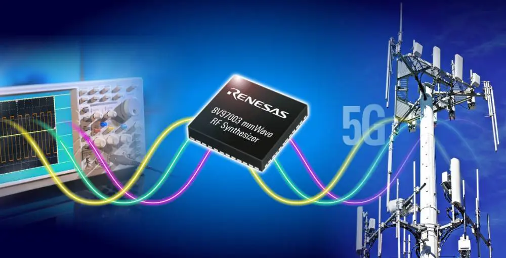
Millimeter wave refers to the band of spectrum having wavelengths between 30 GHz (10 millimeters) and 300 GHz (1 millimeter). Although 5G is in the early stage, industries are currently focusing on integrating this technology and work out how to support it. Technology has advanced and the way we use web. The features we could only get in a desktop computer are now available in our palms with more advanced features.
Our mobile phones are not only the devices that utilize networks. There are other devices that share the same networks with our tablets and smartphones. These devices include internet-connected vehicles, smartwatches, and smart appliances like thermostats and refrigerators.
Millimeter waves ensure the workability of 5G networks that offer improved reliability and speed. Also, 5G networks integrating MM wave would create opportunities to various data-heavy applications. Furthermore, it can offer enough bandwidth for the development of internet-connected devices. It can also create opportunities for other applications like traffic management, autonomous vehicles, and education.
5G is the most recent cellular network. It is the fifth generation cellular network. Also, it is the newest wireless standard that will be available for a few years. MM wave is very crucial for the future of 5G. It is laying the foundation for 5G performance. Millimeter wave helps to realize the maximum potential of 5G. Furthermore 5G mmWave reveals the capacity and fast throughput that enhances cost-efficient unlimited data plans.
MM waves in 5G can only cover indoor and outdoor environments sue to the limitations. However, it won’t cover both environments together. This means that an antenna transmitting MM waves put outdoors won’t penetrate buildings and homes to offer 5G connectivity to users inside. Also, this is the same for people who are connected to an antenna indoor.
MMWave is a crucial element and a building block of 5G system. The 5G MM Wave can offer differentiated services. Therefore, it makes it an ideal investment all mobile operators should integrate in their 5G network deployment. Also, millimeter wave is a technology integrated by 5G. It is what completes 5G. Also, the deployment of millimeter wave in 5G helps to discover immediate user experience and enjoy the benefits of network efficiency.
5G MM PCB is a type of circuit board that integrates 5G millimeter wave. Presently, 5G is the new manufacturing and design challenges for high-frequency boards. Therefore, the 5G mm wave PCB is suitable for high-frequency applications. The PCB industry requires metrology and new imaging techniques to fabricate 5G mm PCB.
There are several manufacturing technologies poised to offer inspection and imaging capabilities required for more complex and higher quality boards for 5G. Also, mmWave refers to electromagnetic waves whose wavelengths are short. Shorter wavelengths produce higher frequency. Therefore, mmWaves signals produce high frequencies.
A 5G MM PCB provides higher frequencies in applications. In telecommunication, the 5G MM PCB plays a crucial role. Also, this offers higher frequencies and signal integrity when used in devices. Also, higher frequency signals can carry more data. This indicates more bandwidth and much faster network speeds.
Due to 5G MM PCB capabilities, devices that integrate this board can provide maximum speeds of about 4-5Gbps. However, consumer speeds can be lower. Also, mmWaves are much faster than some wired fiber broadband connections. 5G mm PCBs are widely used across applications that require faster data connection and higher frequencies.
Furthermore, the integration of mmWave technology in this PCB allows faster speed data transmission. Therefore, the main highlight of this PCB is 5G mmWave. Also, this PCB provides bigger capability for users.
Benefits of 5G MM PCB
5G MM PCB offers higher network speed rate. Asides this benefit, 5G mmWave offers a lot of advanced benefits when used in applications.
High bandwidth
5G mmWave frequency band can deliver higher bandwidth. Also, speed rate will be higher when the bandwidth is wider. Data transfer is similar to the transportation of goods between two places. Let’s say the goods transported represent the data. The distance between the starting point and the receiving point represents the electromagnetic wave.
Therefore, quick delivery of goods to the receiving point will require increasing the lanes so that more trucks can travel at one time. More lanes mean more trucks can transport goods in a unit time. Also, this is similar to the way bandwidths transmit more data. Therefore, higher bandwidth results in faster data transmission.
Higher return on investment
This is one of the benefits of 5G mmWave businesses and consumers enjoy. 5G mmWaves offers better satisfaction and user experiences for consumers and business. Also, this results in critical monetization possibilities and opportunities for operators.
Rich resources
The electromagnetic wave’s frequency used becomes higher as wireless communication develops from one generation to another. 5G MM PCB must integrate more frequency resources to have a higher network speed.
Low latency
5G MM PCB offers low latency. This benefit will improve video streaming and surveillance. Also, this benefit will enable new opportunities now and in the future.
5G MM PCBs are ideal for use in advanced manufacturing technologies. Many applications that utilize advanced mobile broadband will benefit from high network. In addition, 5G mmWaves circuit boards are ideal for application that demand increased data capacity. Also, this circuit is ideal for mission-critical applications.
5G MM PCB is widely used in security scanners, telecommunication systems, and more. The high bandwidth provided by this PCB makes it the perfect choice for short-distance wireless transmissions. 5G MM PCBs are also crucial in the medical industry. Also, communication devices used in subway stations, factories, and offices need 5G MM PCB. You will find 5G MM PCB in applications like:
You must have heard some news about 5G, maybe not for good reasons. This is because several people and companies are concerned about the effect of its bandwidth on human health. However, 5G will continue to contribute to technology evolution now and in the future. Also, the short transmission distances and high bandwidth provided by this PCB makes it ideal for use in several applications.
There are several software packages for designing circuit boards in today’s world. As the electronic world advances, so is PCB design. More advanced boards are needed for manufacturing compact and powerful electronics. The process of PCB manufacturing usually begins with PCB design.
Some PCB design software packages are very popular among PCB manufacturers. These software include Eagle, OrCad, and Altium Designer. However, there are other software packages that offer great results. Also, it is advisable that hardware entrepreneurs and starters start with a less popular PCB design package like Geda and DipTrace.
Although these two software packages aren’t as popular as some other software, they offer great features. Altium is expensive and as such, few engineers opt for this software. Most PCB developers like freelance designers, entrepreneurs, and hackers usually can’t afford this software. Therefore, there are other power, yet cheaper alternatives like DipTrace and Geda. In this article, we will consider DipTrace Vs Geda PCB.
DipTrace is affordable, powerful, and easy to use PCB design software. It is suitable for hobbyists. Also, DipTrace provides advanced features that help to create complex or simple multilayer PCBs from schematic to manufacturing files.
Also, this software features four different modules. One of the modules is for PCB layout while another is for schematic entry. Another module is for creating new components and the last module is for creating new landing patterns. Also, these modules are schematic capture, PCB layout, component editor, and pattern editor.
Schematic capture
The schematic capture is a PCB design tool that offers support to multi-level and multi-sheet hierarchical schematics. Also, this tool allows you to convert circuits to a PCB. Spice export and verification enable full project analysis.
PCB layout
The PCB layout module features shape-based autorouting, 3D previewing, smart manual routing, and advanced verification. Class-to-class rules and net classes can define design rules. Also, DipTrace offers a design process which produces reports of errors on the fly before making them. You can preview the board in 3D and export for any mechanical CAD modeling.
Also, this module ensures great quality of final design by comparing source schematic and verifying net connectivity.
Component editor
The component editor module designs schematic symbols for components that are not in the library of components. Also, this module features pad numbering and bulk pin naming features that enable a designer to create multi-part complex components with several pins.
Pattern editor
The pattern editor creates PCB landing patterns for components that are new. Also, this module features 3D modeling. 3D modeling enables designers to preview the boards with attached components at any design stage.
DipTrace is the first intuitive CAD software that offers advanced features like:
Smart manual routing tools
Multi-sheet and hierarchical schematics
High-speed signaling
Manufacturing output
Advanced verification and real-time DRC
Shape-based autorouter
Wide export/import capabilities
Real-time 3D PCB preview and STEP export
Good support and tutorials
Disadvantages of Using DipTrace
DipTrace has got its own drawbacks despite the benefits it offers. Also, the main drawback of this PCB design software is that it is not as standard as Eagle or Altium. For instance, you may want someone to design your PCB layout. This is quite challenging when using DipTrace.
When outsourcing a PCB layout in DipTrace, you will need to export the schematic to a PCF file. After that, you will redraw the new software package manually. Although DipTrace can import PCB layouts and schematics from Orcad or Eagle, it can’t export to these formats. This is because most PCB design software packages make export to another package difficult since they don’t want you to opt for another package.
What is gEDA?
gEDA is a PCB design software package used for electronic design. Also, it is an EDA (electronic design automation) application suite. gEDA is commonly used in printed circuit board design. gEDA applications is collectively known as gEDA suite.
gEDA is a great tool for schematic capture, PCB prototyping, electrical circuit design, and PCB production. Also,the gEDA project provides free software applications for electronics design. This PCB software design is highly preferred among PCB manufacturers.
gEDA is an open-source software package that feature several tools. The centerpiece of gEDA is gschem. Gschem is a schematic designer. Also, this PCB design software allows you to draw electronic schematic with the gschem tool. The electronic schematics describe the structure of a circuit.
Furthermore, these schematics comprise symbols. Symbols represent different components of the circuit and are usually obtained from a library. Also, networks represent the connection between components. gEDA features gattrib. Gattrib is a program for editing the attributes of a component. Furthermore, this PCB design software features a library of functions known as libgeda to manipulate schema and symbols.
The netlist in this software offers a flexible and sensitive utility that help to analyze the schemas to produce some results. Also, gEDA can produce BOMs and DRC reports for our schemes. There is a gsch2pcb that helps to streamline workflow.
gEDA as a design suite features the following tools:
gaf
gaf means gscheme and friends. It is the authentic gEDA project tool the team created. Also, gaf is a subset of different crucial tools. The gEDA development team maintains these tools. These tools include:
gschem is the primary circuit schematic capture program of gEDA. Also, gscheme features a compact user interface with several functionalities. You can draw schematics on the workspace. The different quick access buttons on the user interface allow easy use of the tool. Furthermore, the tool captures all connections and components drawn.
gEDA suite helps to store the schematics’ netlists for more operations.
Gnetlist is a program that generates netlists of different connections and components utilized in the schematic creation tool. Also, gnettlist supports over 20 netlist formats.
Libgeda is a library collection for gnetlist, gsymcheck, and gschem
Gsch2-pcb forwards annotations to the layout tool.
PCB
This is the major PCB layout program of gEDA. PCB as a component of gEDA is suitable for use across all major platforms like Windows, Unix, Mac, and Linux. Also, the tool offers several features like check design rules, trace optimizer, and schematic/netlist import.
Gerbv
This is the gEDA’s gerber file viewer. Also, gerber is the major data format for circuit board design operations.
NgSPICE
NgSPICE is a PCB stimulator ideal for digital mixed-signal circuits. This tool is easy to use and understand and as well as compact.
Icarus Verilog
Icarus Verilog is a simulation and compilation tool written in Verilog data. It is a tool for source codes. Linux is the main target platform. However, it is compatible with some similar operating systems.
DipTrace and gEDA are both PCB design software packages. However, there are some differences between these software packages. DipTrace comes in different prices for various packages. The cheapest version is the DipTrace Sarter is available for 75 dollars. DipTrace Full provides unlimited signal layers and unlimited pins for $895.
DipTrace versions all feature humongous parts library. Also, gEDA offers huge libraries of components. gEDA is more expensive than DipTrace. DipTrace is budget friendly and as such, it is ideal for hobbyists and freelance engineers. The user interface of gEDA is more intuitive than DipTrace.
DipTrace feature four important modules for PCB design. gEDA features several components like Gerbv, gaf, and NgSPICE. These components are all crucial in ensuring good PCB design.
Some Crucial Criteria for PCB Design Software
There are diverse PCB design software packages available. Some packages don’t offer the feature you need. Therefore, you need to consider some crucial factors when choosing PCB design software.
Ease of use
This is a critical feature when choosing PCB design software. DipTrace is a great software package in terms of ease of use. Integrating this software for your PCB design will help a lot. With DipTrace, you can start designing your PCB as soon as possible with a minimal learning curve. You don’t need to waste time learning how to use the software. Also, Geda is a good choice too. Geda features a nice interface for both beginners and experts.
Cost
DipTrace is one of the most affordable PCB design software packages you will ever come across. This software is just half the price of Eagle or one-eight of Altium’s price. Geda is a good option when considering budget-friendly software. DipTrace offers a low or no barrier to entry since you can start with its Starter version.
Both Geda and DipTrace feature huge libraries of components. Also, a large library is crucial since designing new components can lead to errors that any verification tool won’t capture. However, you will need to design some custom components regardless of the package. Although Eagle and Altium offer huge libraries, DipTrace and Geda feature extensive libraries.
Conclusion
The gEDA and DipTrace PCB design software packages are very efficient and make PCB design easier. When it comes to DipTrace vs gEDA PCB design software, both software packages are ideal for use. This is because they offer a good user interface which makes it easy for beginners to understand how the software works.
In this present scenario, the thin film circuit boards have evolved as one of the most important aspects of human life. Almost every field comes with the involvement of thin films in it; it is a solid fact that can’t be denied under any given situation. In the year 1912, the first use of thin films was witnessed.
Thin-film technology uses microsystem technology processes and semiconductors in order to pave the way for circuit boards on organic or ceramic materials. The metal disposition method of this particular technology, followed by its top-notch flexibility, sets it apart from printed circuit board technology.
The substrates or interconnection carriers in thin-film technology allow connection densities, high-precision geometrics of insulators and conductors material, and excellent thermal conductivity. As a result, these excellent technologies bless individuals with maximum reliability in no time.
Since the substrates in thin film technology are potent enough to deliver appropriate technical solutions, they generally entail higher costs when compared to thick-film substrates and printed circuit boards.
Keep reading this article to grab valuable insights about its wide range of applications, types, and uses. Stay tuned till the very end.
What Is the Morphology and Structure of Thin Films?
Thin film properties and microstructures solely depend on deposition parameters, growth mechanisms, and various techniques that are employed during the manufacturing procedure. Check out the three types of microstructures stated below in this article:
Polycrystalline: It forms micro or nano crystallites that come in varying sizes
Amorphous: It forms crystalline lattice in a perfect manner
Epitaxial thin films: It tends to form a solid crystalline film that, too, with latticework
The thin-film applications solely rely on the thin-film morphology, which in turn, depends on a broad range of factors. Some of them include the following:
Atom absorption
Deposition parameters
A flux of vapor and atoms
Type of material
Film thickness
Growth structure
What Are Some of the Benefits of Thin Film Technology?
Go through the unparalleled benefits of thin film technology mentioned below in this write-up:
● It Comes with a Low Cost
When compared to the thick film circuit, these thin film circuits come with lower costs. According to research, it is quite evident that the overall cost of thin film circuits is as less as 10% to 20% than thick ones.
● It Comes with Low Power Consumption
It is one of the major reasons why these thin films are preferred over thick film technologies.
What Are the Different Uses of Thin Films in Everyday Life?
Let’s dig deeper to uncover some of the common uses of thin films in your everyday life. Take a quick look at the pointers mentioned below:
● Use of Thin Film in a Semiconductor
The discrete semiconductor devices, along with integrated circuits, are manufactured from a bunch of thin films of semiconductor, conductive and insulating materials. This exclusive technology has boosted the possibility of miniaturization of a plethora of semiconductor devices such as diodes, BJTs, MOSFETs, and FETs.
● Use of Thin Film in Optoelectronics
Optoelectronics is yet another crucial field where thin film technology has paved its way in the best possible manner. Several individuals have used this thin film technology with an approach to produce batteries that are inserted into the chips.
● Use of Zinc Oxide-Based Thin-Film Applications
ZnO or zinc oxide thin film applications are used in various industries such as optical, thermal, electrical, and magnetic. But, semiconductor coating and devices involve the major use of ZnO thin films. Some of the other applications include:
LED
OLED
Displays
Gas sensors
Solar cells
Photodetectors
Biosensors
Lasers
ZnO is a popular option since it is readily available, chemically and physically stable, comes with incredible conductivity, and is inexpensive in nature.
● Uses of Thin Film in Combating Wearing and Corrosion
Thin films tend to contribute a lot in protecting the metallic parts, thus combating their corrosion in the best possible manner. Several possessions such as wrist watches, jewelry, and knives are safeguarded with proper coating in order to deal with corrosion.
Check out the different kinds of thin film coatings stated below in this article:
TCO Coatings
TCO, or Transparent Conductive Oxide, is a type of thin film that is used in the field of electronics. You can mainly find them in display space and optoelectronics. Check out some of the common applications of TCO coatings:
Biocompatible hard coatings are typically used in the medical field. Their core aim is to boost health outcomes and safeguard implanted devices in this highly sensitive market. Some of the examples of biocompatible coatings are:
Titanium aluminum nitride
Titanium nitride
Titanium carbo-nitride
Chrome nitride
DLC Coatings
Diamond-like carbon coatings or DLC are popular for their top-notch properties. Its lubricity, hardness, and scratch and chemical resistance properties are beyond remarkable. Some of the common uses of DLC coatings are:
These thin film circuit boards can be fitted easily in various areas. Both the fields of industrial applications and consumer electronics enjoy great benefits while using these thin-film technologies.