
RAYPCB · ENGINEERING REFERENCE
IPC-4761: specify the via structure you need
Distinguish tenting, plugging, filling and capping. Turn a protection requirement into a clear drawing brief, with the right questions for fabrication and inspection.
Original engineering guidance · References checked September 26, 2026
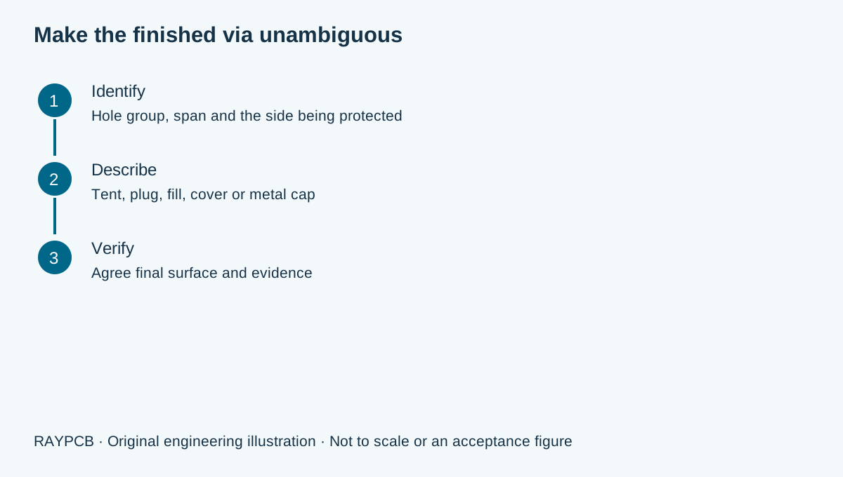
IPC-4761 makes a via-protection drawing less ambiguous
IPC-4761 is a design guide for describing protection applied to printed-board vias. Its practical value is a shared vocabulary: a mask tent, a partial plug, a complete fill and a metal cap describe different constructions. A note saying only “plug all vias” can leave the designer, CAM engineer and assembler imagining different results. Start with the function of each via group, then specify the intended structure and the evidence needed to accept it.
The official IPC document contents identify seven protection types. The publisher's revision register lists the July 2006 document as no longer maintained. That status does not erase a requirement in an existing contract; it does mean a new drawing should identify its reference deliberately and resolve current manufacturing details with the supplier. This guide explains the vocabulary, while the purchased document and agreed drawing control actual requirements.
Do not confuse via protection with the complete interconnect architecture. A buried via, a laser microvia and a mechanically drilled through via describe different hole spans or fabrication routes. Protection describes what happens to the opening and surface. For the larger construction decision, use the HDI PCB manufacturing guide. This page concentrates on the callout that must survive the handoff from design to manufacturing.
Seven types, three questions to ask
| Designation | Construction vocabulary | Question to resolve on the drawing |
|---|---|---|
| I | Tented | Which side has the membrane over the opening? |
| II | Tented and covered | Where is the additional covering required? |
| III | Plugged | Which side is plugged, and what remains open? |
| IV | Plugged and covered | How are plug and cover differentiated? |
| V | Filled | What filling material and final surface are required? |
| VI | Filled and covered | Where does the nonmetallic covering extend? |
| VII | Filled and capped | What metal cap and final pad construction are required? |
This navigation table is not an acceptance table. The original guide contains the detailed descriptions, variants and application considerations. Specify sides explicitly rather than expecting a receiving engineer to infer them from a type number. Include a section view when a pad or interconnect could be interpreted in more than one way. Clear geometry is especially valuable when different protection treatments coexist on the same panel.
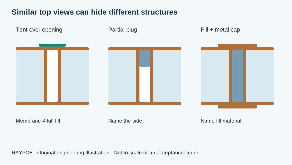
A filled hole is not automatically copper filled. A nonconductive resin fill with a plated metal cap is a different construction from an electroplated copper-filled microvia. Both can appear closed in a top view. Material behavior, processing and verification differ, so name the intended fill and the required interconnect span. Likewise, solder mask covering an opening is not a metal cap and should not be represented as one in a quotation request.
Once the protection vocabulary is agreed, review mask coverage around tented vias or define the fill material, selected population and completed surface. The classification and the process drawing answer complementary questions.
Build a via-protection discussion brief
RAYPCB ENGINEERING
IPC EngineeringVia Protection Drawing Brief
Loading Via Protection Drawing Brief…
Select the construction vocabulary, identify the via group and side, and describe the functional reason for protection. The tool builds a downloadable discussion note and highlights missing decisions. It does not automatically approve a protection type for your pad, choose a proprietary resin or determine an acceptance limit. If your drawing already contains a complete specification, send it directly for review; the worksheet is optional.
Keep the exported note with the exact drawing revision that produced it. A via group called “BGA escapes” is useful only if manufacturing can identify the corresponding holes. Use a drill table, layer-pair definition or marked drawing area, and ensure the data package includes that mapping. If the design changes later, regenerate the note and retire the old one from the release package so conflicting instructions do not travel together.
Why via-in-pad needs more than a closed-looking hole
An opening located in a solderable land can change how solder distributes during assembly. The design discussion should include the intended solderable surface, cap construction, topography, finish and inspection approach. Surface depression and protrusion are engineering concerns because the land participates in printing and joint formation. Their actual permitted limits belong in the applicable acceptance documents and supplier agreement, not in a universal web illustration.
For example, imagine a fine-pitch component with via openings in selected lands. The designer wants a repeatable solder deposit and a continuous finished land. “Mask both sides” does not communicate that need adequately. A better review package marks those land locations, requests a defined filled-and-capped construction for review, identifies the final finish and asks the manufacturer to confirm the achievable surface condition. The example describes a discussion sequence, not a release-ready production note.

Some holes should remain open because their function depends on an opening. Component holes, mounting features and intentional access holes must not be swept into an “all holes filled” note. A fabrication drawing should positively identify the protected via population and exclusions. That simple distinction helps avoid a costly interpretation error that may not be visible until component insertion or final assembly.
Translate intent into five drawing decisions
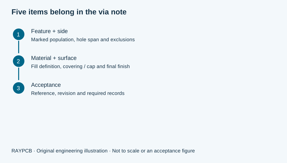
First, identify the hole span and location. Second, name the protection construction and the relevant side or sides. Third, state the fill-material requirement or explicitly request a compatible recommendation. Fourth, define the final surface, including a cap or covering where required. Fifth, identify the acceptance reference and any project-specific evidence. These five decisions should describe the same physical feature without contradicting drill files or solder-mask artwork.
Do not prescribe a shop-floor sequence unless it is a necessary product requirement. The fabricator may use a qualified route that differs from the designer's assumed sequence. What matters at the purchase boundary is the agreed finished construction, its performance and the supporting records. Ask the fabricator to explain any alternative that changes material, surface condition or reliability evidence; an undocumented substitution is not the same as a routine process adjustment.
If two suppliers quote different prices, compare their interpretations before comparing the totals. One may have priced a partial plug, another a complete fill and cap, and a third an additional inspection step. An apparently inexpensive quote can become expensive when the mismatch is discovered after fabrication. A marked cross-section and an explicit via population make those differences reviewable before the order is released.
Decide what inspection must demonstrate
A top-surface photograph can show the appearance of an opening or land, but it cannot by itself establish the complete internal fill or hole-wall structure. A cross-section samples a particular plane and location; it does not magically examine every via on a panel. Define the relationship between the board, representative coupon, sample location and required observation. When measurements are needed, keep their units, method and applicable limits attached to the result.
The IPC-6012 requirements guide explains how rigid-board performance requirements differ from a descriptive construction note. The IPC-TM-650 guide helps organize test-method and reporting questions. A useful evidence request might ask which records demonstrate the agreed cap geometry and internal construction, how the sampled features represent the production design, and how a deviation would be handled before shipment.
Avoid declaring a board reliable solely because the supplier uses a familiar protection label. Reliability depends on the actual stackup, materials, feature geometry, manufacturing route and service exposure. Where a new combination is involved, request an engineering review of qualification evidence. A prior successful board with a different hole span or thermal history is context, not automatic proof for the new design.
Control cost by protecting the features that need it
Cost depends on the via population, fill and cap requirements, material compatibility, processing route, surface expectations and verification scope. There is no defensible universal percentage premium for “IPC-4761.” Two boards with the same type label can require very different work. Share the real drill data and design constraints so the quote can address the actual construction rather than a category name.
Consider whether protection is required for every via or only a defined group. Do not remove necessary protection simply to reduce price; instead, make the functional requirement visible so engineering can assess alternatives. Moving an opening outside a solderable land, changing an escape pattern or accepting another surface construction may affect routing and assembly. Any change needs design approval and a new released data set before it becomes a manufacturing instruction.
For a quotation, provide board size, quantity, layer stack, hole groups, surface finish and required records. Identify the drawing revision and state which decisions remain open. Use PCB Manufacturing for the overall fabrication route, or send the marked requirements to RAYPCB for a focused review. Attach the worksheet manually; opening Contact does not transfer your entries automatically.
Questions engineers ask about IPC-4761
Does Type VII mean solid copper throughout the hole?
No. The label describes a filled-and-capped construction; it should not be used as a substitute for an explicit fill-material requirement. Identify the material and cap expectations, then verify the agreed interpretation against the applicable document and manufacturing drawing. A surface photograph alone cannot distinguish all internal constructions.
Can I use one protection note for every via size?
Only after checking that the note describes the intended result for every included feature and that the manufacturing route supports it. Different hole spans, diameters and pad functions can need different treatment. A grouped drawing callout is usually clearer than a blanket instruction with undocumented exceptions.
Is tenting the same as filling?
No. A tent spans an opening; filling addresses the hole volume. Covering and metal capping add further distinctions. Use the interactive brief to organize the terminology, then agree the finished structure and inspection scope with the fabricator. Do not assume a visual mask closure proves the hole is filled.
Is this a free copy of the standard?
No. This is an engineering explanation and original planning worksheet. The official contents and revision-register links help identify the reference; obtain the complete authorized document for its detailed provisions. The original illustrations on this page are conceptual and do not reproduce IPC acceptance figures or establish project compliance.
Bring the requirement and the drawing together
Send the board revision, construction, quantity and the standard or engineering question you need reviewed. Identify unresolved requirements so the response can address them.
Send requirements for reviewOptional: attach the downloaded worksheet manually. This guidance does not certify a design, approve a shipment or replace the applicable authorized standards.

