AC Circuit Vs DC Circuit – What is the Difference Between these Circuits?

AC Circuit Vs DC Circuit

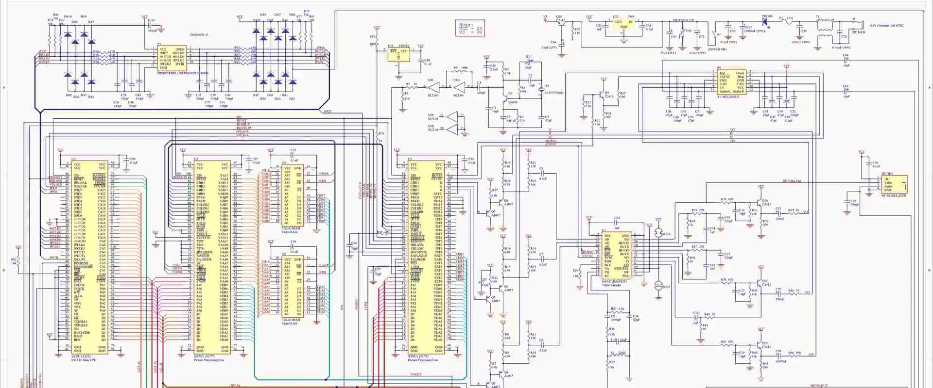
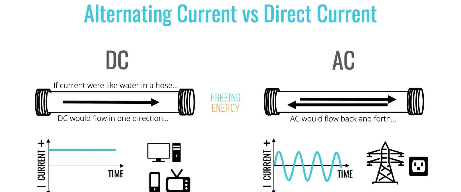
Alternating current (AC) and Direct Current (DC) are the two main types of electricity. Also, these two circuits show the structure of circuit systems.

Inductors, resistors, and capacitors are the primary components of AC circuits. These are all passive electrical components. They have got one common property which is that they all restrict the flow of electric current in a circuit coil. However, they do this in different ways. Our main focus in this article is AC Circuit Vs DC Circuit.

What is an AC Circuit?

Alternating Current Circuit is a type of circuit in which an alternating source powers. This alternating source could be voltage or current. Also, an alternating current or voltage is a type that the amount of current or voltage changes about a distinct mean value.

The voltage and current source has a phase angle in an alternating current. Dividing the resistance by the impedance helps you calculate source voltage and current.  Also, the phase angle has a good effect on the average power the RLC circuit is provided with.

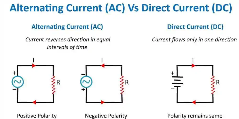
Therefore, one can define an alternating current (AC) as a type of electrical current that alters its value with time and reverses direction. It is different from a direct current (DC), which only travels in one direction.

The sinusoidal voltage and current have been integrated in power businesses and homes for some years of electric power. The AC circuit is the type of circuit that uses alternating source. Also, the AC serves a wide range of domestic and industrial purposes. The direction and magnitude of the voltages and current in an AC circuit has no constant value.

Different Terms Integrated in AC Circuits

Alternating Current vs. Direct Current

Different terms are frequently integrated in AC circuits. These terms include wave form, cycle, alternation, frequency, amplitude, time period, and instantaneous value.

Wave Form

Plotting (I) of an alternating quantity along the Y-axis and the angle or time along the X-axis generated a shape. The shape obtained due to this occurrence is what is referred to as Wave form. (I) here refers to instantaneous value.

Cycle

One complete cycle occurs when an alternating quantity completes negative and positive values completes or when the values go through 360 degrees electrical.

Amplitude

Amplitude refers to the highest negative or positive value an alternating quantity obtains in a complete cycle. It could be also referred to as maximum value or peak value. Vm and Im represent the amplitude of voltage and current respectively.

Alternation

Alternation refers to one-half of a cycle. Also, its span is of 180o electrical.

Frequency

This is simply the number of cycles an alternating quantity makes per second. Frequency is usually measured in hertz (Hz)  or cycle per second (c/s). Also, it is denoted by (f).

Time Period

Time period is the time it takes a voltage or a current to complete one cycle. Time period is usually measured per second and it is denoted by T.

Instantaneous Value

Instantaneous value refers to the value of current or voltage at any instant of time. I or e represents instantaneous value.

AC Circuit Types

FULL PCB MANUFACTURING Quote

AC circuits are available in different types. There are AC circuits having only capacitance (C), only inductance (L), only resistance (R). Some AC circuits combine RC, while some combine LC and some have the combination of the three which is RLC.

RLC AC Circuit

The RLC AC circuit has the combination of resistance, inductance, and capacitance.  It is a type of AC circuit that features a capacitor C, a resistor R, and an inductor L attached in a parallel or series.

The instantaneous voltage over the resistor (R) works in line with the instantaneous current while the instantaneous voltage across the capacitor (C) is behind the instantaneous current. The instantaneous voltage over the inductor (L) drives the instantaneous current.

In an AC Circuit, each voltage canโ€™t sum up. This is because the voltages over the different components are not in phase.

Resistive (R ) AC Circuit

Resistors are electrical components that set, regulate, or impede the movement of current in a definite path. Resistance is the impedance of Resistors. Also, Ohms ฮฉ represents the resistive value of a resistor.

Resistor Inductor (RL) AC Circuit

The RL circuit comprises three different components which are an inductor, a resistor, and an AC generator. The inductor coil generates a back EMF when you activate a circuit switch in an RL AC circuit. Also, it takes the current some time to get to its peak value. The inductive time constant is also known as the time constant.

Applications of AC Circuit

Alternating current  (AC) are widely used in distributing power. One of the main advantages of AC is that you can easily covert it to other voltages. This can be achieved with a simple transformer.

The are lower losses if power is distributed at a high voltage.  For example, a 250 volt supply that carries a  ฮฉ wire resistance  and 14 amps. The power carried is like 1000 watts since watts = volts x amps. Therefore, power loss is calculated as I2 x R = 16 watts.

Therefore, power transmission requires high voltages and these voltages are reduced to a safe level for use within domestic properties. AC is also widely used in supply system. The alternating current is commonly used motors and other items without conversion to direct current.

What is DC Circuit?

DC Circuit

The direct current (DC) circuit is a type of electrical circuit that comprises resistive loads (resistors) and current sources. Also, the DC circuit doesnโ€™t work with time, so, it is independent of time. A circuit is a Direct current circuit if it doesnโ€™t need any past value of its current and voltage.

Since it doesnโ€™t require any past value of its voltage or current, it doesnโ€™t integrate any complex calculation that comprises transient period. Also, a circuit can be referred to as a DC circuit if powered by DC sources like DC power supply or battery.

Direct current is the propagation of electric charge in an unidirectional way. This current is widely integrated  in solar cells and batteries. Also, the DC current was invented by Tomas Edison. This current helped to power a good number of complex electrical systems.

The direct current only flows in just one direction. For instance, a battery provides direct current in a circuit that lights a bulb with a battery.

Applications of DC Circuit

Direct Current circuit is available in applications that have low and extremely low voltage, particularly for solar cells and batteries. Also, the majority of electronic devices need DC power supply and DC voltage. It is important to consider the polarity of DC when using DC devices. Otherwise, you will break it.

It is advisable to connect the appropriate polarity even if your DC devices feature a diode bridge element. DC voltage is widely integrated in the automotive sector. For instance, electric vehicles are making use of DC voltage. These vehicles use batteries.  Also, DC voltage systems are commonly used in diesel engines in heavy duty machines, heavy trucks and machines.

The telecommunication technology isnโ€™t also left out. This technology makes use of DC power supplies. Also, this power supply is useful when there is a disruption during operation as it plays a significant role in maintaining the connection lines for subscribers.

High voltage power transmission integrates DC electricity since the losses by HVDC are cheaper and lower in long distance transmission.

Common Applications of DC Circuits

Batteries

Non-rechargeable and re-chargeable batteries supply DC. Also, the rechargeable batteries use direct current to recharge themselves.

 Electronic equipment

 Electronic equipment such as computers, televisions, and radios among others integrate direct current to power their circuits. Integrated circuits need direct current to power them. These circuits will get damaged if there is a supply of reverse polarity. Although a good number of these items is powered by Alternating current.

Some electrical equipment

Some pieces of electrical equipment integrate alternating current. However, there are some that integrate direct current.

 Solar panels

 Solar panels generate direct current from the solar panels themselves. These panels generate electricity. When these panels are used with AC mains to supply into the mains for AC supplies, an inverter is needed to enable the conversion of the DC from the solar panels to AC.

AC Circuit vs DC Circuit

There can be a decision based on which current to use in several areas. It is important to know the difference between AC Circuit vs DC Circuit. Also, you should know the form of supply ideal for a particular application.

AC Circuit vs DC Circuit has their benefits and limitations. However, this means you can choose the best option for any particular use or application. Generally, Alternating current (AC) is ideal for use in power distribution. This is the reason the main sockets in offices and homes supply an alternating current. This current powers anything you plug in the main sockets. However, direct current is commonly integrated for printed circuit boards and for many other applications.

Both AC Circuit vs DC Circuit are both widely integrated across electronic and electrical industries, with each providing distinct benefits and ideal for use in different applications. Also, both currents can offer electrical power transfer. However, they do this with slightly different benefits.

Alternating current and direct current are different in terms of power transmission, power generation, and power distribution. However, the main difference between the direct current and alternating is the direction of the flow of electricity. This also serves as the foundation of their diverse characteristics. Furthermore, there is continuous flow of electrons forward or in a particular direction in Direct current.

This is not the case in the AC system. Here, there is exchange in the direction of electrons movement in periodic intervals. Also, this alternating current (AC) makes the voltage value alternate as the value changes along from negative to positive based on the current.

The magnitude of AC varies with time while the magnitude of DC is constant. AC source includes all forms of AC mains and AC generators. DC source include batteries.

Frequently Asked Questions

Why is DC stored in batteries?

You should understand that batteries donโ€™t directly store the energy in them. Batteries are designed to store electrical energy in chemical energy form. In this case, the AC sourceโ€™s positive terminal connects to the batteryโ€™s positive terminal and the AC sourceโ€™s negative terminal is connects to the batteryโ€™s negative terminal. When all these happen, the current begins to flow. However, there is a change in the polarity and there is no supply of the energy. This occurs because the negative half cycle is cancelled out by the negative half cycle. The battery can become damaged if this process persists. Therefore, AC is not stored in batteries.

What are the advantages of AC over DC?

AC has some benefits over DC. One of the advantages of AC over DC is that AC is less costly. Also, it is very easy to generate AC. You can transmit AC across long distances without experiencing much loss of energy. On the other hand DC is very expensive and it experiences energy loss during transmission.  Furthermore, DC is more expensive.

Why is AC voltage preferred over DC voltage?

In most cases, AC voltage is usually preferred to DC voltage. This is because transmission in AC voltages produces less loss of energy. On the other hand, DC voltages experience much loss of energy during transmission. Since AC voltages result in less energy loss, it makes it easy to install when transformers are far away.  Furthermore, AC voltage can step up and step down according to requirement. This is an added advantage.

Conclusion

Both direct current (DC) and alternating current (AC) are both widely integrated across electronic and electrical industries, with each providing distinct benefits and ideal for use in different applications. Also, both currents can offer electrical power transfer. However, they do this with slightly different benefits.

Alternating current and direct current are different in terms of power transmission, power generation, and power distribution. However, the main difference between the direct current and alternating is the direction of the flow of electricity.

All You Should Know About the .Schematic File

.Schematic File

Are you unable to access your SCHEMATIC file and simply curious as to what it contains? We describe the purposes of these files and demonstrate tools that, in our experience, can open and otherwise work with your files.

What Does a .SCHEMATIC file Mean?

Your device can only open files with a SCHEMATIC file extension, according to it. This SCHEMATIC type of file may, however, be utilized by other programs for a variety of data kinds.

Even though we haven’t yet discussed the format of the SCHEMATIC file and its typical applications, we know the type of applications that can open these schematic files because we receive some suggestions about particular file types as well as the applications people are using to access them every day from users just like you.

If you possess knowledge regarding SCHEMATIC files which you believe would be helpful to others, kindly drop it in the comments section; we will really love to get your response. We are constantly striving to add new descriptions of file types onto the site. ย 

More Information of the Schematic File

layout
layout

The first version of the Minecraft is called Java Edition. Notably, players can improve their gameplay by using a range of unauthorized add-ons as well as mods with this Java Edition of Minecraft. Several Minecraft mods let users create replicas of their homes, landscapes, monuments, or even whole worlds in the form of SCHEMATIC files.

Players may import their creations into some other Minecraft world, open and edit them with third-party types of Minecraft modding software like MCEdit, and more by using SCHEMATIC files. They will also be able to share all their structures through the internet with some other players.

SCHEMATIC file is saved in the.NBT file format used by Minecraft and contain a wide range of different binary data which describes the size and make-up of a structure. A structure’s height, width, and length are specified in all SCHEMATIC files, together with the materials as well as the kinds of blocks that make up the building.

Modders found that, as a result of technological changes, they couldn’t import and export structures as the SCHEMATIC files when Mojang published Minecraft Edition 1.13. Due to this, a large number of mod creators switched from this SCHEMATIC format into a SCHEM format, that was developed by the same team in charge of Sponge, an Minecraft open-source modding framework.

Opening .SCHEMATIC files

Several tools for Minecraft mods allow you to open as well as edit the .SCHEMATIC files.

Most significantly, the Minecraft game editor MCEdit (Linux, Windows) has the ability to open the .SCHEMATIC files. While modifying a level, click its Import button to load the .SCHEMATIC file in the MCEdit. By choosing Export Schematic upon selecting a structure, you could also export this structure as SCHEMATIC file.

There could be a number of reasons why a SCHEMATIC file won’t open. The initial as well as most significant reason (also the most frequent) is that none of the installed programs on the device are suitable or support SCHEMATIC.

Finding and downloading the right application is a pretty straightforward solution to this issue. The task’s initial phase, which is installing its .SCHEMATIC file, has already been completed.

Simply download and then install the necessary application at this time.

Opening the SCHEMATIC Files on Windows

In Windows Operating system File Explorer, locate the relevant SCHEMATIC file, and double click it to start the associated program.

If the SCHEMATIC file cannot be opened by an application but you receive the error message “Windows cannot open the file,” you should hunt for any application that can open this problematic file.

Furthermore, if you are aware of an application that can read Schematic files, try running it to see if the File->Open menu option is available.

If you’re unsure of the program that opens Schematic files, try searching online for “Schematic viewers,” “Schematic file application,” or you can search “open a Schematic file.” Do this using any search engine that you love.

Next, Install that program you have discovered online, and then see if it will be able to open the SCHEMATIC files.

Is it Possible to Convert the SCHEMATIC file be converted into SCHEM file?

FULL PCB MANUFACTURING Quote

There is currently no simple method for changing the SCHEMATIC file into the SCHEM file. However, you can use SchemToSchematic (Web) as well as Mineways to convert the SCHEM files into SCHEMATIC files to ensure that the structures present in them are useful in Minecraft versions prior to 1.13. (Windows).

Potential Issues with the Files in Schematic Format

It’s not always the case that your computer lacks the necessary software if you are unable to read and use the SCHEMATIC file. We might also be unable to handle this MCEdit Schematic File due to other issues. Here is a list of potential issues users can face.

  • SCHEMATIC file that is currently opened becomes corrupt.
  • Incorrect registry entries that link to your SCHEMATIC file
  • Inadvertent removal of the SCHEMATIC description from Windows registry
  • An application which works with your SCHEMATIC format was improperly installed.
  • Unwanted malware has been embedded in your .SCHEMATIC file that is currently being opened.
  • The machine lacks the hardware resources necessary to handle opening of your SCHEMATIC file.
  • Out-of-date drivers for the hardware that the computer needs to open the SCHEMATIC file

When you are certain that none of these causes apply to your situation (or are already ruled out), your SCHEMATIC file ought to work with the programs with no issues.

If the issue with your SCHEMATIC file is still not resolved, it can be because there is an additional, and more unusual issue with your .SCHEMATIC file in this particular circumstance. The only thing you have to do in this situation is approach a competent staff for help.

Conclusion

Hope you now know what .schematic file does and what it offers. We have also discussed the potential issues users may face with this file.

What does a .DXF File Mean?

.dxf file

This file is described as the Drawing Exchange Format created by Autodesk as a means of storing the CAD models. Furthermore, the theory behind this is that when the format of the file is supported by different 3D modeling software, then they will all easily export and import the very same documents.

This file format, also known as Drawing Interchange Format, seems to be comparable to that DWG file extension-based Drawing Database format from AutoCAD. However, because .DXF files may be found in a ASCII, text-based format, which is naturally easier to use in these kinds of applications, they are more frequently employed in CAD systems.

DWF files, however comparable to other files, are utilized to transfer files online as well as through a free program. DXF on the other hand are majorly for interoperability.

For more applications to open AutoCAD files, Autodesk created the .DXF file format as an open and universal standard. For instance, its Valve Hammer Editor allows you to export the 3D models in form of DXF files, which you can then import and edit in other applications for 3D like ACD Systems Canvas and Autodesk AutoCAD.

Ways for Creating the .DXF file

Depending on the CAD application, several processes are required to create the DXF file. For instance, in AutoCAD, click File, then โ€œSave Asโ€, and then select DXF format out from the menu bar to produce the DXF file.

Opening .DXF Files

Both the DWG TrueView application and the Autodesk Viewer are free viewers offered by Autodesk. You can see the DXF files which are kept in the online services for file storage like Dropbox using the AutoCAD mobile app as well. Utilizing ShareCAD is another fast online file opening method. It also functions with the Dassault Systรจmes SolidWorks’ eDrawings Viewer.

The Design Review and AutoCAD programs from Autodesk, as well as CorelCAD, TurboCAD, ABViewer, CADSoftTools’, Adobe Illustrator, as well as Canvas X Draw, are some additional programs that are compatible.

The file can be opened on macOS using Cheetah3D and a few of the tools indicated above. Utilizing LibreCAD, Linux users will be able to work using the format.

Since ASCII DXF files are simply text files, every text editor can be used to open them. However, doing this prevents you from viewing the drawing as you would for actual model viewers. There will only be various groups of numbers and letters.

Converting the .DXF File

DXF files can be converted to various formats by a number of programs, including CorelCAD and AutoCAD.

In order to convert the DXF file into SVG, use the Adobe Illustrator. Utilizing a free web converter such as Convertio is an additional choice. With the trial edition of AutoDWG DXF Converter, then you can get it in DWG format (both older and newer versions). This software has a 15-day usage limit and can only be used on one file at a time.

One can save their work in a number of formats, including ZIP, EDRW, HTM, EXE, TIF, BMP, PNG, and JPG, using the eDrawings Viewer application stated above.

One way to convert it to PDF is to go ahead and upload it into the DXFconverter.org then go ahead and select PDF as the output format. The file can also be saved to JPG, PNG, TIFF, and SVG on that website. Adobe Acrobat may also be used to convert .DXF file into PDF. If you need to save your .DXF file into the STL format, Bear File Converter can be handy.  An NGC file extension can be added to the .DXF file in order to save it in the G-CODE designed for the Linux CNC format.

You can transform the file’s text content so that it can be used with Excel and any other spreadsheet program. This is possible by converting the file into CSV using MyGeodata Converter.

The file might also be convertible to another format, such as the AI file of the Adobe Illustrator, using any of these viewers up above.

.DXF File Still Not Opening?

If neither of these services or programs are able to open your file, make sure this file extension truly does read.   

Also, DXF rather than a similar format like OXT. Even while many files have similar file extensions, that doesn’t necessarily mean that these formats are connected or that the software supports them.

For instance, DXL as well as DXR both run with programs unconnected to a CAD software described here. DFX is a comparable one. This one can be utilized with the AutoCAD as well because the document is a CAD type.

More Details About the DXF File Format

FULL PCB MANUFACTURING Quote

You may have one DXF file in the binary format as well as another present in the ASCII since the DXF format’s standards have changed since it was first introduced in 1982. The specifications are available as a PDF on the website of the AutoCAD.

Both binary DXF as well as ASCII files are all supported by more recent editions of AutoCAD. However, you only can deal with the files of the ASCII DXF if you are making use of the Release 10 (this has been available since 1988, although it’s doubtful).

The sections of a DXF file are HEADER, TABLES, CLASSES, ENTITIES, BLOCKS, THUMBNAILIMAGE, OBJECTS, and the END OF FILE. The PDF that is provided above has all the information on every section.

You may download DXF files for free from a few websites, including myDXF and Scan2CAD.

Frequently Asked Questions

Does Photoshop support DXF export?

No. Due to the fact that DXF files represent vector files and are often handled by applications such as Adobe Illustrator, Photoshop does not support the direct exporting into DXF.

What purposes do DXF files serve?

The design and engineering of products, as well as the creation of photorealistic models to serve advertising campaigns, all make use of the DXF files.  DXF files provided various compatibility solutions in the CAD industry, enabling collaboration between engineers and artists on a single file format.

Conclusion

We hope you understand what the .dxf file is, and how to open it. If there is any aspect of this article you need some clarity on, please contact us.

5G Antenna vs 4G Antenna: Whatโ€™s the Difference?

5G Antenna vs 4G Antenna

5G is widely known as the most recent mobile network, which has been designed to take the place of 4G technologies offering some improvements with respect to reliability, coverage, and speed.

In this article, 5G vs 4G antenna, we will be taking our time to explain what 4g and 5g is, and how they differ. We will also talk about how beneficial they are to humans.

Flying High Using 4G

Imagine you as well as the opera suspended 30 meters from the ground. Even so, you can only move above and then below the singers this time. You are also still rotating in a 30-meter-diameter semicircle, but this time, it is vertical. Again, one will clearly hear their country’s anthem when it is being sung by the singers; however, as you move upwards, the sound will progressively become quieter.

Finally, you will only hear very little whenever you’re levitating about 30 meters just above the singers. A 4G antenna helps in radiating on vertical planes like this. Once more, the majority of signal radiation is directly infront of that antenna panel, and as you go away, it eliminates or reduces intensity.

Getting Louder Using 5G

5G Antenna

Now let’s hand a bullhorn to every opera singer. This sound is suddenly considerably louder. Imagine that you are currently circling the opera in a vertical or horizontal semicircle. This time, when you move, the singers start directing their bullhorns at you.

No matter where you are, the sound is always just as loud it was whenever you were directly in the front of your opera because it is accompanying you. 5G antennas function in this manner. The opera singers’ head movements are dynamic beamforming, which tracks a user as theyโ€™re moving from the middle of the panel of the 5G antenna.

Why Choose 5G

The main reason and focus or requiring an upgraded and a better network is just to support all the rising increases in devices demanding internet access. A good number of them require much bandwidth to help it function normally, which the 4G canโ€™t just accommodate anymore.

Furthermore, the 4G network was released in 2009 and made available to the public, As at 2021, the mobile networks now carry about 300x additional traffic than it carried back in 2011. Furthermore, 5G makes use of different antennas, they also operate working on different frequencies of radio spectrum, and more devices will be able to connect to internet, deliver very fast speeds, and then reduce delays.

5G Doesnโ€™t Work the Same Way as 4G

If it weren’t fundamentally distinct from current networks in some manner, a new kind of network wouldn’t qualify as novel.

Greater radio frequencies

One fundamental distinction is the usage of particular radio frequencies by 5G to accomplish what the 4G networks will not be able to.

As you ascend into greater frequencies, this radio spectrum will then be divided into bands, with each having its own characteristics. Although there are 5G networks that utilize higher frequencies, such as those at least 30 GHz, 4G utilizes frequencies under 6 GHz. One significant benefit of these high frequencies is that they support an enormous capacity for rapid data. They can be employed in future to meet rising bandwidth demands because they are highly directed and less congested with present cellular data.

This is significantly different to the 4G towers, which might possibly waste power and energy by beaming radio waves in places where people aren’t even trying to access the internet.

Shorter wavelengths

Additionally, 5G employs shorter wavelengths, allowing for the use of considerably smaller antennas while maintaining accurate directional control. In comparison to 4G, 5G could support more than 1,000 more gadgets or devices each meter since a base station could make use of additional directional antennas.

All this translates into 5G networks being able to broadcast fast data with a high precision as well as low latency to a large number of users.

However, the majority of these extremely high frequencies only function when there is a straight, unobstructed line of sight formed between the device and the antenna accepting the signal.

In addition, some of the high frequencies were readily absorbed by dampness, rain, as well as other substances, which reduces their range.

Because of these factors, a robust 5G connection that is present wherever you are may drop to the 4G speeds whenever you go a short distance away. One method of addressing this is the use of carefully placed antennas, which can be either small ones put in certain buildings or rooms that require them or enormous ones spread out across a metropolis.

In order to extend radio waves to the greatest extent feasible and support long-distance 5G, it is important for several repeating stations as 5G grows.

The ability of modern networks to move into the lower mode of power when it is not used or when providing low rates into specific devices, as well as to do so while switching to higher-powered modes for things such as video streaming in HD, is another distinction between 5G antenna vs 4G antenna. ย In fact, compared to earlier networks such as 4G, 5G is up to 90% more efficient with respect to energy, according to certain studies.

5G Is Much Faster Compared to 4G

The quantity of data which can be transferred (downloaded or uploaded) via a network in a specific amount of time is referred to as bandwidth. This means that a device might possibly experience what’s called peak speeds under perfect circumstances where there are extremely few, if there are any, other devices as well as interferences to alter the speed.

5G is about 20x faster compared to 4G in terms of peak speed. Thus, you may have downloaded 20 times as much data via a 5G network in the time you took before downloading just a piece of content using 4G (such as a movie). Another way to look at it is that before 4G can deliver the first part of any movie, you can download nearly ten of them!

While 4G’s maximum download speed is only 1 Gbps, 5G’s minimum speed for download is 20 Gbps. These figures apply to stationary devices, such as those in FWA configurations, where a specific direct wireless link exists between the device of the user and cell tower. Once you’re moving, such as in a train or car, speeds change.

Due to the numerous other factors that influence bandwidth, these aren’t typically called the “standard” speeds that these devices experience. The measured average bandwidth or realistic speeds should be the focus instead.

Although 5G coverage has been expanding rapidly, the majority of people presumably still don’t always have access to the 5G speeds, thus it would be unfair to draw conclusions from regular real-world observations.

Despite this, some sources indicate that average download speeds are just 100 Mbps (Verizon’s 5G service provides data between 300 Mbps to about 1 Gbps).

5G Antenna vs 4G Antenna: Features Present in 5G That are Absent in 4G

FULL PCB MANUFACTURING Quote

It’s obvious that 5G has been creating new roads into the future to serve communication and mobile devices due to the obvious differences regarding the way they perform, but what does this truly mean for you?

You can still access the internet, make calls, send messages, and also stream videos using this next-generation network. Actually, nothing you presently do on the phone in terms of internet access is diminished when you go to 5Gโ€”they are simply upgraded.

When adopting this technology, websites load more quickly, multiplayer games online lag less, and there is realistic and smooth video when you are making use of FaceTime, and more.

Because 5G is just so fast, everything you’re doing online now that appears to occur fairly quickly would appear to happen instantly.

More Features

You may connect more devices to your internet at once without experiencing capacity constraints if you employ 5G in your home in replacing your cable. Several internet connections for home are very slow to the extent that they cannot support the latest connected technology that is being released today.

Your wireless thermostat, Smartphone, consoles for video gaming, smart locks, headset for virtual reality, wireless cameras for security, tablet, as well as laptop may all be connected to a single network using 5G from home without you having to worry about them all turning off at once.

The airways are now open for further internet-enabled technology like traffic lights, mobile wearables, wireless sensors, as well as car-to-car communication, when 4G fails to meet the data requirements of an increasing number of devices.

It isn’t a fair assumption to believe that all this can be handled by the 4G networks. Vehicles that get GPS data as well as other instructions which assists them in navigating the road, including software upgrades, traffic alerts as well as real-time data, need fast internet in order to always remain on top.

Given 5G networks can send data much faster than the 4G networks, then it is possible to anticipate that there will be an increase in the amount of data transfers that are uncompressed and raw in the future. Information may now be accessed even more quickly because it doesn’t have to be decompressed.

5G Antenna vs 4G Antenna: Safe distances

Returning to the initial setup now, one listener stands facing the opera, who is about 30 meters distance away. No loudspeakers. Imagine the listener begins to approach while remaining directly facing the opera. That volume of the sound increases. The sound eventually becomes really loud, and then their ears begin to suffer. The user retreats till the pain subsides. Let’s say the distance to the opera is 5 meters. This represents the bare minimum fair distance from which you can listen to this opera without risking eardrum damage. The same principles govern the mobile wireless network.

The greatest electric field strength facing the antenna is set by a governing authority. Engineers can use the maximum intensity of the electric field to determine its safe distance. Getting too close could hurt your body if you are nearer than the established safe distance. The precise safe distance is dependent on a number of variables.

More on Safe Distances

Returning to the current situation, We just said that when you’re standing right at the middle of this opera, your safe distance becomes 5 meters. In the previous 4G scenario, we discovered that shifting away from that exact center reduces the sound’s intensity. We hear far less if we stand 5 meters from the spot but completely toward the side. In such situation, our ears won’t ache even when we get closer than the 5 meters.

Because of this, you can stand right beneath 4G panel antennas even though your distance from the panel is closer than the minimum safe distance.

Let’s examine the reasonable distance for the 5G cases. Here,  the volume is stronger and opera singers are using bullhorns. Now, 10 meters from these singers, our ears begin to hurt. This safe distance is not only greater, but it also remains constant regardless of the listener’s position because opera singers accompany them as they are moving around. As a result, this safe distance from the middle of your panel for the 5G antenna, including the areas directly below and above the antenna, is 10 meters throughout all directions.

Although in practice this safe distance may change slightly depending on the position of the UE in relation to its panel, this is the way things work inside the Radiofrequency world in theory.

Where Can I Get 5G?

Since its rollout is still in progress, you cannot have access to all 5G networks anywhere (unlike you definitely will with 4G). In the majority of densely populated regions, you can connect to a faster kind, but in the majority of urban and rural areas, you can only connect to the slower type (or nothing at all)

Conclusion

We hope we have done well concerning the differences between 5g antenna vs 4g antenna. Clearly, 5g is more advanced and with greater features.

60/40 Vs 63/37 Solder โ€“ What are their Similarities and Differences

60 40 Vs 63 37 Solder

Solder is a metal alloy that comprises lead and tin. The combination of thin and lead is what produces solder. Also, these two materials are usually melted using hot iron. There are several parameters that determine the composition of solder. These parameters include reflow characteristics, melting point, and creep behavior among others.

In most cases, tin accounts for more percentage than lead. In this article, we will be comparing the most common solder compositions which are 60/40 Vs 63/37 solder. What is the difference between these two types of solder and what benefits do they offer?

What is Solder made of?

Solder is a material used in creating a strong bond between metal parts. It is a metal alloy that combines different materials like tin and lead. Traditionally, solder comprises tin and lead with more percentage of tin.  Solder is generated by melting the solder. For solder to create a strong bond, its melting point should be below the pieces it is joining.

After the melting phase, the solder cools down and the parts bond permanently. In electronics production, engineers make use of solder to fix components to circuit boards. Therefore, solder used in this field must have great conductive properties. For many years, tin and alloy have been used to make solder.

As time went on, there were concerns about the environmental and health hazards of lead. Therefore, this made lead-free solder more commonly used in recent times. Typically, solder features a low melting point which is always around 200 degrees Celsius.

Also, solders are available in different form factors. Some solders are specially designed for specific applications or industries.

Types of Solders

60 40 Solder

There are two major types of solders based on the use of lead. These are lead alloy solders and lead free solders.

Lead alloy solders

These types of solders comprise lead and other metals. 60% tin and 40% lead or 63% tin and 37% lead are the most common composition. Also, leaded solder feature very low melting point which is usually about 180 degree Celsius. Therefore, this makes then bond materials well. Also, it is easy to work with leaded solder. Lead alloy solders feature properties which make people refer to them as soft solders.

Furthermore, the use of lead in this alloy has the formation of tin whiskers. Lead is a dangerous substance as it is poisonous to humans and their environment. It can contaminate ground and soil water. The EU restricted the use of hazardous substance by issuing the Restriction of Hazardous Substances directive in response to the concerns about the use of lead.

Lead free solder

Lead free solders comprise different metals. Tin serves as the base material of this solder. Lead free solders offer more strength to alloy. Other metals used include nickel and silver. However, the melting points of lead-free solders are higher than leaded ones. Therefore, lead free solders have more stress on components during PCB assembly. Furthermore lead-free solders donโ€™t flow well and they tend to form less strong joints.

Manufactures had to develop solders that feature unique properties to prevent these problems. For instance, tin-silver-copper alloy features a very low melting point of 217 degrees Celsius. The integration of Silver helps in reducing oxidization. Also, copper enhances mechanical strength and conductivity. The mixture of nickel in alloy or the use of conformal coatings can help in preventing tin whiskers from forming.

What is 60/40 solder?

FULL PCB MANUFACTURING Quote

60/40 solder is a metal alloy that comprises 60% tin and 40% lead. It is also referred to as alloy Sn60Pb40. This solder is one of the alloy in the soft solder family. The melting point of 60/40 solder is very close to eutectic temperature. However, it is still referred to as non-eutectic solder. Also, 60/40 solder melting point is 190 degree Celsius. This solder flows well and it is very easy to use.

60/40 solder features good properties such as exceptional thermal conductivity and electrical conductivity. Furthermore, this solder composition creates a strong and permanent bond in metals. The 60/40 solder is ideal for use in electronics and PCB manufacturing.

It is crucial to store this solder in a non-corrosive and dry environment. The temperature of the environment should be between 10 to 40 degrees Celsius. One of the drawbacks of the 60/40 solder is that it is not eutectic.

The 60/40 solder features a high melting range. Also, this solder is suitable for joining copper and copper alloys. However, it is not suitable for joints exposed to vibration or shock. The 60/40 solder is available in solid wires, acid core, and rosin core. This solder is ideal for use in dip soldering baths due to its narrow melting range.

60/40 solder is a perfect option for soldering electronic and electrical connections. Also, the heat sources used include air-fuel torches and soldering guns. The 60/40 solder is ASTM B32 Alloy Grade Sn 60;J-STD-006 Sn60Pb40Sb0.4.

Also, this solder is soft. This implies that cracks donโ€™t easily form if there is movement in the joint during cooling.

What is 63/37 Solder?

The 63/37 solder is a metal alloy that comprises 37% lead and 63% tin. This melting point of this solder is 183 degrees Celsius. 63/37 solder has a lower melting point compared to 60/40 solder. One of the benefits of the 63/37 solder is its eutectic property.

The 63/37 solder is eutectic and as such doesnโ€™t feature a semi-solid state. Therefore, it is much easier to work with since it doesnโ€™t produce much bad joints. Furthermore, the 63/37 solder is ideal for use in hand soldering application due to its properties. Also, it is commonly used in plating and wave soldering. During plating, 63/37 solder serves as a coating to prevent corrosion. It is also a base for soldering.

63/37 solder is available in foils, solder paste, and bar among others. This solder is also referred to as 63Sn/37Pb.

Difference between 60/40 vs 63/37 Solder

The main benefit of 63/37 solder is its narrow temperature range. This solder usually melt and becomes solid at a single temperature. The melting point of 60/40 solder is higher than that of 63/37 solder. The fact is that 63/37 solder features no plastic region. This means the solder solidifies quickly when it cools down. On the other hand, 60/40 features a plastic region.

The 63/37 solder is eutectic. Due to the cost of tin, this solder is more pricey than 60/40 solder. 60/40 solder was manufactured due to the high cost of tin. Therefore, it served as an alternative when cost is a major factor. The 63/37 solder features slightly more mechanical strength than 60/40. However, the 60/40 solder is a popular choice in the electronics manufacturing industry.

One main benefit of 60/40 solder is cost. However, the major drawback of this solder is its 50C plastic region. The 60/40 solder turns to plastic at 183 degree Celsius and melts at 188 degrees Celsius. A cold solder joint forms when the joint moves as the solder moves through the plastic region. Hand soldering can be very frustrating when this happens. The plastic region will have no consequences on the solder joints if the solder joints isnโ€™t disturbed or moved until the solder has become fully solid.

63/37 solder is eutectic. This means that this solder moves from solid to liquid without experiencing plasticity. Since it features no plastic region, the 63/37 solder is better to work with. Joints made using the 63/37 solder look shiner. Therefore, the 63/37 solder has a better cosmetic effect than 60/40 solder. The 60/40 solder is widely used for small connections. However, it is not a good option for portable water or plumbing applications.

The Working Principle of Solder

The composition of alloy impacts the solidifying behavior of solder. Pure metals will become solid at a particular temperature and form crystals. Also, eutectic alloys can become solid at a single temperature. when non-eutectic alloys cools down, the non-eutectic stage starts precipitating in the case of intermettalic compounds.

Furthermore, a mushy state is the combination of solid particles in eutectic. Solder is widely used in different applications. The most common solder type is 60/40. However, flux is also needed in solders to ensure the formation of good joints. Flux prevents oxides from the jointโ€™s area. Also, flux helps in forming a string and good bond.

The type of solder integrated in electronics manufacturing is usually in a wire form. The 63/37 wire solder makes hand soldering easy. Therefore, it is an ideal option in hand soldering applications.

What is the Function of Flux and Rosin Core Solder?

Lead free 60 40 Solder

Flux helps in improving soldered jointโ€™s quality. It prevents oxidization from surfaces. Also, it chemically eliminates oxidation from the soldered surfaces and as well enhances the wetting of the surfaces when applying solder.

There are channels inside rosin core solder. These channels contain rosin flux. The embedded flux will clean the joint before any flow of solder. You should always use resin core solder for electronics. Lead-free and lead alloy solder can be rosin core.

The rosin core has a hollow core. None of the residues of rosin core solder will corrode. Since it is quite difficult to remove residue in electrical connections, the resin core solder is commonly used for soldering electrical products. Lead free and leaded solder can be rosin core. Avoid using acid core solder in electronics manufacturing. This type of solder is ideal for plumbing.

The lead-free rosin core solder is a great choice for soldering electronic components. Also, this solder comprises tin and lead with tin accounting for 60% and lead accounting for 40%. You can use copper in place of lead. Copper is a better option since lead is hazardous to human health and the environment.

Frequently Asked Questions

What is the strongest type of solder?

The 60/40 solder produces the strongest joints. Also, this solder composition has a very low melting point. Therefore, it is very easy to work with. However, it is more expensive.

What is the 50/50 Solder?

The 50/50 solder comprises 50% of tin and 50% of lead. It accounts for half of lead and half of tin. This type of solder isnโ€™t ideal for electronics. It is commonly used for plumbing. If you use this type of solder for electronics manufacturing, it may result in failed joints. This is because the 50/50 solder doesnโ€™t exhibit the properties of 60/40 vs 63/37 solder. Also, the 50/50 solder has lower ductility and higher melting point. Furthermore, this solder can have flux in it just like resin core solders.

Which solder is ideal for electronics?

The lead-free rosin core solder is a great choice for soldering electronic components. Also, this solder comprises tin and lead with tin accounting for 60% and lead accounting for 40%. You can use copper in place of lead. Copper is a better option since lead is hazardous to human health and the environment.

What is flux-core solder?

You will find flux core solder when wires cut in an object. During soldering, the flux releases and gets rid of oxidization built up on the surface of the metal. Then, the surface of the metal is cleaned and ready for soldering.

Is the 63/37 solder ideal for electronics?

Yes, the 63/37 solder is a suitable option in electronics manufacturing. It is commonly used in soldering electronic components. The melting point of this solder is 183 degrees Celsius. The eutectic property of this solder makes it an ideal choice in some applications.

Conclusion

It is crucial to choose an ideal solder composition when building electronic circuits. The two most common solders used are 60/40 vs 63/37 solder. During soldering, it is important to carefully consider the parameters that may affect the performance of your solder. Also, it is crucial to pay much attention during soldering by ensuring the hot soldering iron doesnโ€™t cause injury.

In the electronics industry solder is often considered least. This shouldnโ€™t be the case as solder plays a vital role in the performance of an electronic device. Therefore, it is crucial to understand the properties and nature of solder.

What are EMC Shielding Solutions?

high frequency shielding

EMC shielding or Electromagnetic Compatibility Shielding can be described as a specific approach that ensures sensor signals are well protected from electromagnetic signals from external sources. In addition, it helps in preventing the leaking out of signals, as well as interferes with some electronic devices.

When a specific electronic component lacks shielding, it could lead to some issues, like a down system and interrupted communication.  In addition, EMC shielding focuses on many domains, which includes health, military, as well as emergency services.

What are the Factors for Selecting the Right EMC Shielding Solution?

There is no doubt that EMC shielding plays a huge role in different electronic devices. However, it is very important to choose the best shielding. Below are some of the factors you should consider when selecting or designing your shield.

Level of Attenuation: The attenuation level indicates the signal strength loss. Normally, this falls between 60dB and 100dB. Also, some may have 120 dB too.

Mechanical Durability: Your shielding must possess high resistance to electrical and mechanical failure.

Environmental Sealing: Protecting the components from some external factors such as humidity, dust, water, etc.

Compression: Forces of compression usually has more effects on the functioning of the shielding properties of the equipment. This level of compression depends on your material.

Material: Different materials exist and are useful for EMC shielding. Therefore choose one which is based on its usage.

Complexity:ย This indicates that you should also consider the patterns form.

Which Materials are Useful for EMC Shielding

An important stage during EMC shielding is having the appropriate and right materials. Your choice of material depends on some specific requirements, performance, costs, as well as the features of that equipment that requires shielding. Below are some of the materials commonly used.

Copper: This offers a shielding solution that is most reliable for radio wave and magnetic frequencies. In addition, it features a high level of attenuation for the electrical waves.

Tin: This EMC shielding solution is inexpensive and it is great for frequency ranges that are lower. Also, it helps in resisting corrosion.

Aluminum: The cost of Aluminum is less compared to the other metals. Also, it is most frequently used as a result of its high conductance at 60%, and non-ferrous capability.

Copper Alloy 770: The Copper Alloy 770 is made up of zinc, nickel, and copper. It is useful due to its resistance to corrosion. It is great for all MRI applications due to its permeability.

EMC Shielding Applications

EMC shielding is useful in different applications. This is dependent on the type of value that it brings. Here are some implementations of the EMC shielding.

Furthermore, EMC shielding is useful in securing laboratory and medical equipment, whereby the disruption as well as prevention of signal interference is important and lifesaving. It is very useful in medicine, data communications, as well as other types of service transmissions into the theaters and wards of patients. Also, it is useful in many medical devices. These include peacemakers and MRI machines.

EMC shieldingโ€™s main function is the prevention of signals from any interference. This is why it is a very useful application in intercepting data access on the RFID chips, as well as other devices that are embedded.

The facilities of EMC shielding help in the improvement of security measures that are taken in the government, financial, and military services.

EMC Shielding Product Types

FULL PCB MANUFACTURING Quote

EMC Shielding Elastomers

Manufacturers are used to shielding electronic enclosures with the use of conductive elastomers,. This helps in avoiding electromagnetic interference. There is a sandwiching of a unique conductive gasket between a lid and metal housing to help in completing the device for EMI Shielding.

The configuration permits great electrical conductivity via this gasket. Furthermore, the EMC elastomers feature high heat conductivity as well as mechanical durability. These are great for offering both environmental shielding and EMI shielding. Due to their effectiveness, the EMC shielding elastomers play a role in commercial and military devices, and wireless transmission.

HC Filters

The HC Filters can be described as electrical devices that help in getting rid of the transfer of electromagnetic noise in-between the drive and power supply. You can integrate these filters either stand-alone or you can place it on your electronic circuit/board.

Also, the EMC filters are usually arranged in-line. Frequency, on the other hand will get rid of any electromagnetic interference. If itโ€™s a low pass filter, it permits just a lesser frequency. In addition, EMC filter offer applications with respect to their placement. Also, they are usually placed in-between the device, as well as its external environment in order to block entrances of any undesired signal.

Best EMC Shielding Solutions

Harwin EMC Shielding Solutions

This company includes different shield clips (surface mount), shield cans, as well as spring contacts in solving different RFI/EMI as well as grounding issues. Also, the components of SMT are usually given on reel and tape for the automated assembly as well as lowered costs of production. Clips and shield cans gets rid of the need of manual soldering, increasing reliability, and simplifying production.

GETELEC

This sectorโ€™s complexity needs specific knowledge of different infrastructure types, both for the railway signaling and rolling stock. As of today, the transportation sector is responsible for the strategic activity whereby every player makes efforts to strengthen.

Furthermore, GETELEC offers R&D team that designs microwave shielding, environmental sealing and thermal dissipation solutions as a result of its every day technological monitoring.

Laird

Whenever there is a flow or electromagnetic waves, interference could place the very important devices, as well as the peopleโ€™s lives at risk. This is one reason why skilled engineers make use of some coordinated systems that are designed to assist you in building the most effective EMI defenses.

For over two decades, we have been able to perfect an integrated art of the creation of top EMI shielding materials. In contrast to competitors, Laird is in charge of the entire process.

Conclusion

To conclude, shielding is very important where electronic equipment needs segregation from electromagnetic signals, or where extra signals are being transmitted.

Why the .CAD File Format is Crucial in 3D Designs

.CAD File

Are you wondering what a CAD File is all about? Or Are you finding it difficult to open a CAD file. This article gives a detailed explanation on what CAD file does and how to open it. Keep reading to gain more knowledge.

What is a .CAD File?

Autodesk QuickCAD developed the CAD file. The term CAD means Computer Aided Design. A CAD file is a file format of an object produced and integrated by CAD software. Also, the CAD file comprises a blueprint or technical drawing of an item. The computer aided design and drafting (CADD) is widely integrated for a 3D graphics file format.

Also, the .CAD file comprises both 2D and 3D designs and data regarding materials, tolerances, and processes. The CAD file handles everything from design to production. 2D CAD files are usually known as drawings while 3D files are known as models or assemblies.

Not all formats are interchangeable. This makes CAD file format very crucial. You can only view some formats in some particular CAD applications. The format is the characteristics that define the CAD file. These formats are native and neutral.

Neutral formats such as IGES and STEP were industry standards most CAD platforms can read. Also, major CAD vendors produced native formats such as DWG, CATIA, and SOLIDWORKS. You need 3rdย party CAD tools conversion to import these formats.

Importance of the .CAD File

CAD File

You must save a document as a file when using a computer to create one. This file usually has all important details associated with the document and as well contains information on how to visualize and process them.

Also, CAD file formats play a crucial role when CAD design is involved. You are designing a digital document when you use programs like SolidWorks or AutoCAD. The CAD file format specifies the program that helps you view the document. Also, it reveals what the document contains.

Every CAD system describes geometry using its own method. CAD files are capable of storing information for these processes. The two primary categories of the CAD file formats are Non-proprietary and proprietary.  Proprietary CAD file format features what you need from the original design without leaving anything behind. Also, this file format is ideal to share designs.

A non-proprietary CAD file is ideal for use when sharing the documents with external sources. Also, this file format isnโ€™t exclusive to just one CAD program.

Properties the .CAD File can Store

Geometry representation

B-Rep and Meshes are the two commonest means of representing 3D data in CAD files. Also, B-Rep bodies are usually defined through a set of topological entities and geometrical entities. Geometrical entities are means of future visualization. Also, these entities store the data about geometric and dimensions properties of parts.

Furthermore, CAD file formats can vary based on their geometry representation. Topology is a factor of B-Rep. Bodies and elements are included in Toplological shapes. Geometry specifies the form of a body. On the other hand, topology stores connectivity data and specifies underlying geometry.

Product structure

Product structure refers to hierarchy of objects known as groups of objects that are interconnected. Most CAD software applications have a tree view at the left side of the screen. Users can easily expand the groups of this tree. To display or hide model elements, you need to tick the checkboxes.

Visual attributes representation

CAD files have the capability to specify visual attributes like line styles, colors, textures, and materials. Mesh and B-rep elements may have these features.  Considering visual attributes is necessary. These attributes wonโ€™t just enhance the appearance of the CAD model, but also clarify the functionality and structure. Furthermore, .CAD file format may vary based on the availability of a certain attribute and the way it supports. For example, colors may be chosen from a list of basic options or defined through RGB tuples.

Metadata

.CAD files comprise metadata. These include Product and Manufacturing information (PMI), Object names and IDS, layers, and validation properties. Metadata carries out less features of the model. The ability of CAD files to transfer these data varies.

What are the Most Common File Formats?

FULL PCB MANUFACTURING Quote

CAD data usually travel between clients, investors, and contractors. It is crucial to integrated optimal CAD formats that can operate between existing software applications. Below are most common file extensions.

ACIS-SAT file format

This is a native format. It belongs to the ACIS geometric modeling kernel. Also, this kernel paves way for ACIS-SAT application. Also, the ACIS-SAT file format offers support to two extensions which are SAB (standard ACIS Binary) and SAT (Standard ACIS Text). The SAT enables the manual tweaking of the model contents. SAB, on the other hand, is more compact.

STL file format

Stereolithography (STL) file format is specially designed for 3D printing. However, it serves other purposes asides from 3D printing. It is extensively used in CAM workflows and laser scanning. Most multi-purpose CAD packages offer support to the STL.  Also, the CAD modeling tools support the STL file format. However, the absence of connectivity information results in low performance and inaccuracy.

STEP file format

STEP means Standard for the Exchange of Product model data). This file format comprises several Application Protocols (APs) which include AP 203 for assemblies and mechanical partsโ€™ 3D designs. AP 242 is speculated for model based 3D engineering. The APs cover all primary aspects of manufacturing and design. Also, STEP file format is compatible with various 3D modeling, CAD, and CAM software applications.

VRML file format

VRML means Virtual Reality Modeling Language. This was the first 3D format specially designed to showcase 3D scenes on websites. Also, the .VRML file format allows visitors on the website to communicate with virtual objects. A plain text file is the commonest form of VRML. However, there is a gzip-compressed extension. Also, the VRML file format comes with sophisticated features like references to audio and keyframe-based animation.

Conclusion

We have gathered a lot of knowledge on what CAD files can offer users and their importance. Also, we have discussed most common file formats for CAD.

How to Open and Convert an .SCM file

.scm file

This might be your first time of learning about the .SCM file and you are wondering what it really does. Also, you might be reading this article because one of your files ends in .SCM file. Well, you are not alone as this article provides answers to all the questions you have concerning the .SCM file.

What is the Function of an .SCM file?

A .SCM file is developed by the GIMP Team. This file comprises videos shot with ScreenCam. A ScreenCam is a type of recording software based on Windows. Also, the .SCM file saves SCM-encoded. The .SCM file comprises a movie produced while running the system and as well comprises contents on your computer screen.

The scheme language offers support to associated techniques like recursive algorithms. Also, you can open and edit the .SCM files in any text editor like Apple TextEdit and Microsoft Notepad. You can play the .SCM files in different media players if you install the SuperMV SCM code.

.SCM file is a commonly used file extension. This type of file comprises various formats for a wide range of programs. Also, .SCM files comprise video ย recordings ScreenCam captures. The .SCM filename extension saves SCM-encoded audio and video content.

Problems you May Encounter When Opening Your .SCM file

FULL PCB MANUFACTURING Quote

People often complain about the inability to open their .SCM file. There are a lot reasons why you may not be able to open the .SCM file. However, the most important and evident reason for not being able to open your .SCM file would be the lack of an ideal software. You need well-suited software that offers support to SCM among those installed on your device.

For instance, the GIMP is suitable for opening your .SCM file. Failure to use the appropriate software will give you more problems. You will get a message like โ€œWindows canโ€™t open this fileโ€ if you donโ€™t use the appropriate software.

Below are potential problems you may encounter in your .SCM file

Sometimes, your .SCM file may not open not because of an inappropriate software. There are other reasons your .SCM file might not be opening. Therefore, it is important you know these problems beforehand. This will be of great help to you. Your .SCM file might fail to open if:

  • You delete the description of the SCM
  • The .SCM file opened is already corrupt
  • There are wrong links to the SM file
  • The .SCM file you are trying to open has an undesirable malware
  • The installation process of an app supporting the SCM format isnโ€™t complete
  • Your computer uses out of date drivers of equipment to open your .SCM file
  • There are no enough hardware resources on your computer

If all of these donโ€™t exist, your .SCM file should work well with your programs. However, if you are yet to solve the problem with the .SCM file after considering all the problems listed above, there may be a very rare problem with your .SCM file. You need a professional help in this case.

Which Programs can Open and Convert .SCM files?

The good news is that there are several programs that can help you open and convert your .SCM file without stress.

Grand Theft Auto III by ROcksatr

This is an action-adventure video game. The major character in this game involves in crime while seeking for revenge. The mission script of this game is usually saved in the .SCM file.

ICQ by ICQ

This is a messenger that supports video conferencing. With this program, users can convert audio messages to text. Also, they can use smart replies to respond to messages. The compressed sound scheme of the ICQ is usually saved in an .SCM file. Audio is the classification of this file format.

SadefCam by SADEF

This series of 3D programs are outdated. However, they have building components you can integrate in a third-party software like Hypersteel, Stucad, and AutoCAD. SadefCam uses .SCM file. This file is an export file that comprises whole-group data for a task that requires steel manufacturing. You can classify this file format as 3D image.

ScreenCam by SMArtGuyz

This is a video editor and screen recorder that is based on Windows. It supports automation and exportation of movie to standard file formats. Also, ScreenCam captures screen recording and stored it in .SCM file before the recording is exported to a standard format like MP4 or MOV.

StarCraft

This is a Sci-Fi video game based on a military settings. It has a game set in a universe where there are three main intelligent species fighting for dominance. This game stores maps used in them in .SCM files. You can classify this File format as Game.

Other Programs that Can Open Your .SCM file

SchematicMaker by Topanga

This was initially a Windows-based application used in designing schematic diagrams for electronic circuits, timing diagrams, and PLC ladder. This program stored some of its data in the .SCM file. Data is the classification of the file format.

Spanish Whiz by Braser

Spanish Whiz was initially designed for learning Spanish. Also, it helped people expand their Spanish vocabulary and pronunciation skills. This program saved scrambled game sounds in .SCM files. Also, Audio is the classification for this file format.

Media Player by Microsoft

This is a multimedia player. You can use it to p;ay video and audio .SCM files . The file format for this program is usually classified as Video.

SammyGo ChanEdit by SamyGO

SamyGo ChanEdit helps in editing configuration data that are directly exported from Samsung TVs through USB. You can store TV channel lists you exported from SamsungTV through USB.

Frequently Asked Questions

What does a file extension mean?

A file extension is usually at the end of a filename. It is a set of three characters. File extensions reveal the type of file you have.

How can I open unknown files?

Many files comprise simple text data. Also, while you are opening unknown files like SCM, it will enable you to have a preview of the content of several files.

Conclusion

.SCM file is a commonly used file extension. This type of file comprises various formats for a wide range of programs.

50 Ohm vs 75 Ohm: Which is Better for your Application?

50 Ohm vs 75 Ohm

Finding the best cellular booster for your needs is made easier when you know the coax cable that you require. Some people just require 50 Ohm while others require 75 Ohm. You can discover your optimal booster kit with ease if you have a better understanding of what they are as well as what the Ohm is. Learn the distinctions between 50 Ohm vs 75 Ohm to determine which is best for you.

The terms 50 Ohm vs 75 Ohm impedance are frequently spoken when discussing S-parameters,   transmission lines,  impedance matching, and other essential ideas in Radiofrequency/ high speed circuit board design. Search the internet for component datasheets, design specifications, application notes, impedance values, as well as signaling standards, and this impedance value keeps coming up.

How Does Ohms Work?

Electrical resistance’s SI unit used to measure the cable’s electrical resistance is the ohm. The SI Unit defines an Ohm as the electrical resistance present between two locations or points on a conductor. The performance is enhanced if the cable does have a lower Ohm value.

Since the Ohm scale measures electrical resistance, it’s crucial to take note of what you require and the cable’s Ohm. To choose the best booster cable, you don’t have to get technical about calculating Ohm, though. Understanding the distinction between 50 Ohm vs 75 Ohm is crucial.

What Does 50 Ohm Mean?

50 Ohm

Surprisingly, booster performance improves as the Ohm value decreases, therefore systems using 50 Ohm are usually stronger compared to those having 75 Ohm. Even though 50 Ohm is more powerful, most homes as well as small buildings don’t need it because it may cover anywhere between 7,500 – 100,000 square feet. Similarly, these wires are around 100 feet long.

You can choose between 50 Ohm vs 75 Ohm booster cables for cellular signal by being aware of the many types available. Since 50 Ohm cables are stronger than 75 Ohm cables, they may strengthen the signal across a wider area. These cables also feature N connectors for connecting the antenna as well as booster.

In the air dielectric coax, a fair compromise between the power handling as well as loss control is 50 Ohm. The coax cable can be used in commercial installations having cable lengths of more than 100 feet and a maximum of 100,000 square feet. Devices requiring high power for handling like TV/radio transmitters, routers, Ethernet networks, Wi-Fi, etc. typically utilize cables of 50 Ohm.

Numerous forms of study have been conducted using 50-ohm impedance, and engineers could use it as a compromise to achieve the greatest power with the least energy losses.

The development of the telecom sector occurred late 1920s and into the early 1930s, which is when 50 Ohm impedance first appeared. Coaxial cables packed with air were being designed by engineers for the radio transmitters with kW power output. Additionally, these wires would be able to go hundreds of kilometers. In order to get the maximum highest voltage, power transfer, as well as lowest attenuation, the cables must be designed in this manner.

What Does 75 Ohm Mean?

The applications for 75 Ohm are audio and video, which accounts for its quick adoption and widespread use in the nation. The maximum installation size for a home as well as small structure is 5,000 square feet, and they work extremely well for different home applications that can reach 50 feet cable.

A figure that is recognized for all varieties of high frequency coaxial signal connections is the impedance of 75 Ohm. The measure of the electrical resistance that serves the alternating current is known as impedance: An alternating current flows into a cable when the alternating voltage is provided at one end of the cable. The impedance is defined as ratio of the voltage to the current.

However, the open circuit, not of 75 Ohm, will be measured when using an Ohm meter to measure the coaxial cable that is 75 Ohm between its core and shield. This is due to the fact that your meter usually measures utilizing direct current, or DC resistance rather than AC resistance.

 Furthermore, one could believe that 75 Ohms would be a lovely, round figure that’s simple to remember, however according to an article, this was done on purpose. The diameter of coaxial cables having steel cores is slightly enlarged to provide a little extra flexibility; therefore the impedance works out to be 75 Ohms.

These are common coax cables used in residential and business buildings. AV signals are typically transmitted via cables of 75 Ohm, which can transport signals to reach 50 feet with any possible installation.

High definition TV signals, cable and satellite boxes, etc. can all be connected to this line. Capacitance acceptance and low attenuation are for these data signals, A/V, as well as digital audio are likewise provided by 75 ohm.

What are the Differences: Comparing 50 ohm vs 75 ohm?

FULL PCB MANUFACTURING Quote

It ultimately comes down to two factors when comparing 50 ohm vs 75 Ohm: power and footprint. This holds especially when comparing coax lines with cables of 50 ohm vs 75 ohms.

In essence, impedance is used for measuring cables, or the amount of resistance present to the electrical energy flow. When it comes to increasing cellular signal, the 50 Ohm cable performs far better than cable of 75 Ohm.

The radio frequency that you are seeking to transmit depends significantly on the signal loss present on the 50 Ohm vs. 75 Ohm cables. Certain cables of 75 Ohm perform better compared to the 50 Ohm cables present at extremely high frequencies.

However, popular solutions of 50 Ohm always offer better loss compared to the cable of 75 Ohm like RG-6 when it comes to enhancing cellular signal. The majority of home cell phone boosters use the 75 Ohm system and 75 Ohm cable, like RG-6 having F-connectors.

The majority of commercial boosters of cell signal use LMRยฎ400 using N-connectors, which are systems of 50 Ohm having 50 Ohm cables. For increasing cellular signals, the 50-ohm connection, for instance, performs substantially better. Furthermore, if the range of frequency is higher, the 75 Ohm cable would work best.

Therefore, any use of the coaxial cable necessitates a thorough understanding of the prerequisites. The 50 Ohm cable typically feature larger connections and are thicker. Additionally, if the building isn’t already prewired for 50 Ohm connections, running cable may be more challenging. These cables are less common than 75 Ohm types.

Some varieties of the 50 ohm cables feature greater loss of signal compared the RG-6 75 Ohm cable therefore ensure that the spec cable you are getting is LMRยฎ400.

50 Ohm vs 75 Ohm: Coaxial Cable Comparison

Technically speaking, the information is excellent; however it doesn’t really help you decide if you require either the 50 Ohm or the 75 Ohm type of coaxial cable. The 50 Ohm cable is indeed the standard of the industry and best option for devices which require greater power characteristics and minimal electrical power loss.

The 50-Ohm cable works best when it is combined with transmitters or transceivers, so keeping that in mind as you sort through your alternatives is a great rule of thumb. So the 50 Ohm cable would be ideal for walkie-talkies, radios, Wi-Fi, broadcast transmitters, as well as mobile phone repeaters.

The 75-Ohm cable performs best, however, when energy storage isn’t a concern and the goal is to transfer a signal across a cable as efficiently as possible without wasting any energy. You should choose a 75-Ohm cable when turning on electronics such as HD televisions, Blu-ray players, home theater equipment, and similar items. Whether you choose the 50 Ohm vs 75-Ohm cable to complete the task, this should depend on the suggested application of the electronic gadget.

Transforming the Reference Impedances

We typically employ S-parameter measurements for significant metrics for signal integrity when dealing with high-frequency and high-speed channels.

All these are specified with respect to some given reference impedance that is typically taken to be any of the aforementioned values (either 50 ohm vs 75 ohm), given that your RF/high-speed system may be interacting with any of the media. You’re aiming for either 50 ohm or 75 ohm impedance for every port, as well as S-parameter measurements inform you how your design has drifted from this objective. It is preferable to think about reference impedance concerning your target termination impedance.

Systems using 75 Ohm operate well in structures smaller than 5,000 sq ft. The majority of specialists concur this is perfect for the majority of household and owners of small businesses.

Homeowners typically purchase either RG-6 or the RG-11 cables for their boosters, both of which give 75 Ohm.

Conclusion

Understanding the variations between 50 Ohm vs 75 Ohm enables you to more accurately determine which meets your needs. Homeowners frequently purchase 75 Ohm systems, but if they reside in the rural regions, they might require something stronger and more reliable. Any questions, please message us.

What is Cable Interference Shielding?

Cable Interference Shielding

Shielded cables play a huge role in reducing radio frequency interference denoted as RFI as well as electromagnetic interference (EMI) from external devices like fluorescent lighting, air conditioners, cellular networks, power lines, and computers.

Furthermore, EMI has to do with those unwanted signals coming from a nearby transmission circuit. In addition, the shielded cables have the ability to prevent data transmitted from the EMI as well as cross-talk in-between the cable pairs, as well as unintended coupling. What results is a rise in the transmission speed and less data errors.

Reasons Why You Should Make Use of a Shielded Cable

You may think of making use of shielding cables if your office or home is overfilled with appliances and electronic devices or situated close to power lines.

Shielded cables that are well installed are usually designed to help in mitigating crosstalk and EMI coupled with ensuring the integrity of the data, as well as maintaining a great transmission performance and speed. Cable interference shielding doesnโ€™t just prevent crosstalks in-between cables. It also plays a huge role in protecting devices and machines, as well as people.

Furthermore, cables inserted into enclosures, metal cabinets, or from other noise sources donโ€™t need any shielding. This is because they already have some protection from EMI and noise. Also, take note that though shielding could make your cable more robust and rigid, they shouldnโ€™t be utilized in any wet location. This can only happen if they are manufactured specifically for these applications.

Do Shielded Cables Come in Different Types?

Cable Shielding

The use of shielded cables is dependent on the application. Yes, shielded cables come in different types and they are readily available for purchase. However, the three main types that serve signal cables of low voltage include foil shield or Mylar (metal-coated), spiral design, or braid shield. With respect to the construction and design, cable shielding can help in noise reduction by at least 85%.

Braid Shielding

The braid shields are usually constructed through the weaving or copper wires and aluminum wires interlaced together. Also, braid shields can help in noise reduction to a maximum of 90%. In addition, braid shielding will help you cover around 85% of your wire. Also, signal noise could leak in-between the gaps present in the braided weave design.

In addition, the coverage amount has to be sufficient, most especially where some applications donโ€™t need frequent movement flexing. One important thing to consider here is the disadvantage of braid shields design. It is usually more expensive and adds more weight to your final design.

Spiral Shields

Spiral shields are composed of conductive wire, which are wrapped in the form of a spiral surrounding the core of the inner cable. Also, this helps in mitigating noise to a maximum level of 98%.

Just like braids, you can make use of different materials as well as wire sizes. However, these spiral shields only work for mid-sized and smaller cables to help in attaining a greater coverage. Also, they are well-suited for different audio applications and audio frequency range.

Foil Shields

The foil shields usually make use of aluminum foil laminated to a polypropylene or polyester film. Foil shielding has the ability to offer full cable coverage, offer strength, as well as add the needed insulation for the shield protection.

Furthermore, foil shield helps in getting rid of gaps present with the braided designs in deflecting EMI 100%. Foil shielding fails to perform effectively in any high-flex applications in contrast to the braided or spiral designs. However, foil shields possess less weight and are less expensive than the braid or spiral shields.

Ensure that shielded cables are properly grounded on the two ends. This is to enjoy all the benefits that shielding has to offer.

Multi-Shield

It is possible to construct cables with many multiple shielding layers utilizing both the foil and braided designs for the noisy environments. Furthermore, the communication cables can be individually shielded after pairing. This will go further to help prevent coupling and cross talk.

What Shielding Type is Best for You?

FULL PCB MANUFACTURING Quote

The best shielding for all applications has to do with the application in question. The designing of twisted wires is to reduce some of the EMI present in the unshielded cables. However, the extra shielding present in the twisted shielded wire cables is much more effective in the protection of interference.

Furthermore, shielded cables have to be used along with the shielded connectors having some casing or metallic screen, which absorb RFI/EMI and also channels any interference that is unwanted to ground connection.

In addition, the efficiency of shielding is usually affected by the resistance. This makes shields that are wire-based like braids and spirals shielding great for applications with lower frequencies. Also, coverage is known as the major issue when it comes to higher frequencies that makes foil shields having 100% coverage the most appropriate option, most especially in communication and network cables.

How to Choose the Most Appropriate Shielding

Low-Frequency Applications

Spiral or braid shields are usually useful for applications of low frequency (about 1 MHz). Also, for the low frequencies, a shieldโ€™s electrical resistance is a very important factor that helps it become effective.

Medium-Frequency Applications

The usefulness of braid shields can be seen in applications with medium frequency, ranging from 1MHz โ€“ 100 MHz. Furthermore, the effectiveness of the braid shield has to do with the coverage that it offers, as well as the weaveโ€™s tightness. Coverage from the braided shield falls between 65% – 98%. In addition, higher braid coverage causes greater shield performance; however, it usually costs more.

High-Frequency Applications

The combination shields can be viewed as the best, when dealing with high-frequency applications. This is usually higher than 100 MHz. When you combine the foil shield with the braided shield, the energy leaks, which usually come from the braided shield, are blocked.

Conclusion

The main purpose of cable shielding is grinding noise, which the cable picks up. Cable shielding as well as its termination has to offer a very low impedance path into the ground. The shielded cable which isnโ€™t grounded causes disruptions, which could increase the impedance level, as well as reduce the cableโ€™s effectiveness.