
RAYPCB · ENGINEERING GUIDE
EMI Shielding Materials: Compare the Installed Function, Not a Single dB Claim
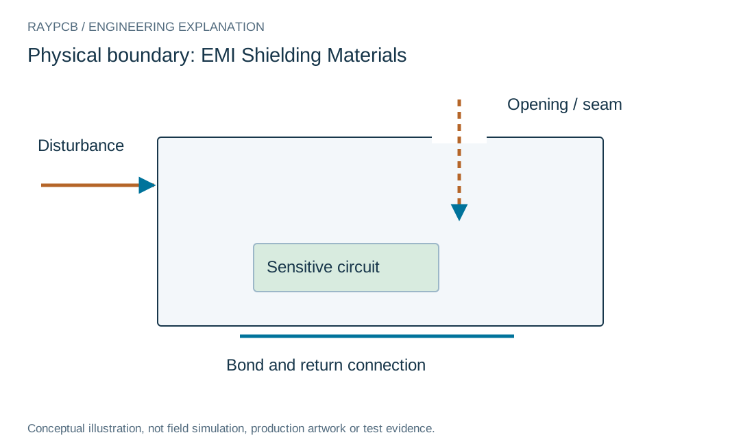
EMI shielding materials include conductive metals, foils, coatings, gaskets and magnetic alloys. Their usefulness depends on field type, frequency, geometry, contact and installation. A material coupon's measured attenuation is not a guaranteed result for a populated product with seams, cables and removable covers.
This page compares the selection questions and provides a same-fixture field-ratio worksheet. Specific foil construction is covered in foil shielding, while magnetic-field limitations are covered in low-frequency shielding.
Define the field and frequency range
Distinguish electric-field, magnetic-field and propagating-wave questions where relevant. Record source and receiver geometry and the frequency range that matters. A material suited to one condition may not solve another.
Avoid choosing solely from a catalog's largest attenuation number. Ask how the data were measured, including fixture, thickness, orientation and contact conditions. The installed design must provide the paths and boundaries on which that performance depends.
Material categories do not specify installed attenuation
| Category | Useful property or role | Interface issue to review |
|---|---|---|
| Conductive sheet or foil | Provides a conductive boundary under applicable conditions. | Seams, openings, surface finishes and connections. |
| Conductive gasket | Supports an electrical contact across a mechanical joint. | Compression, contact surfaces, wear and environment. |
| Conductive coating | Can connect a nonconductive enclosure surface electrically. | Continuity, thickness control, adhesion and contact points. |
| High-permeability alloy | Can redirect magnetic flux within its operating conditions. | Shape, saturation, stress and material treatment. |
Compare conductive construction options
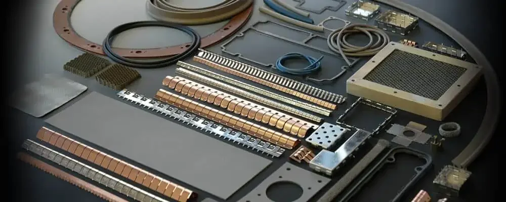
Metal covers and foil can provide conductive boundaries, but need joints and attachment methods. Conductive coatings can support other mechanical forms, while gaskets can bridge removable seams. These functions are complementary rather than interchangeable labels.
Review weight, thickness, forming, soldering, corrosion and service access alongside electrical behavior. A cover that cannot be assembled repeatably or a coating with poorly controlled contact regions may not deliver the intended boundary.
| Review item | What to establish |
|---|---|
| Function | Field type, frequency and installed boundary identified. |
| Interface | Seams, finish, adhesive and pressure are specified. |
| Data | Coupon figures retain their test conditions. |
| Budget | Entered allowances cover the same delivered scope. |
Measured field-ratio shielding reference
Measured field-ratio shielding reference
Use the current inputs and keep the assumptions
Start with the physical boundary named above the inputs. Enter your own values, or select Load example to explore the labeled teaching case. Example mode remains visible after edits so an illustrative result is not mistaken for measured project data. Clear for my inputs removes the sample values and starts a separate record.
Generate the result after completing the relevant fields. Changing an input invalidates the previous output and disables its download until you calculate again. Read the limitations next to the result: a ratio, margin or checklist does not qualify a channel, approve an EMC test or establish a supplier capability.
Download the current result if it supports your review. The text file contains inputs, outputs, assumptions and the tool version. It stays on your device; attach it manually to an enquiry if useful. No CAD or measurement file is uploaded or interpreted, and nothing is automatically inserted into the Contact form. You can ask an engineering question without completing this tool.
| Input | What to establish before using it |
|---|---|
| Review reference | Nonconfidential scope or revision. |
| Unshielded field magnitude | Same field type, units, position, fixture and frequency. |
| Shielded field magnitude | Positive above the measurement noise floor. |
| Entered attenuation goal · dB | Project goal, not a universal material requirement. |
Optional cost comparison from your own allowances
Use a quotation or a clearly labeled internal assumption for each input. Keep the quantity, construction and inspection scope the same when comparing alternatives. This uncalibrated planning model adds entered values; it contains no current market rates and does not issue a RAYPCB quotation. You can contact the team without completing it.
Entered material and verification budget
Treat contact interfaces as electrical features
Specify overlap, surface finish, attachment pressure and the role of adhesive or gasket. A conductive bulk sheet does not ensure a conductive seam. Oxide, paint, contamination and mechanical tolerance can affect the connection.
Include environmental and lifecycle conditions where they matter. Repeated lid removal, vibration or corrosion exposure may change the interface. Keep those requirements with the mechanical drawing rather than leaving them as informal assembly preferences.
Separate magnetic material questions
Low-frequency magnetic shielding can require a suitable permeability, shape and material condition. Saturation, forming and heat treatment may matter. An ordinary thin conductive foil should not be represented as a universal solution to static or low-frequency magnetic fields.
The low-frequency page explains why a skin-depth calculation is only a limited reference. It does not calculate magnetic shielding effectiveness or replace a supplier's application-specific evaluation.
Interpret a measured field ratio
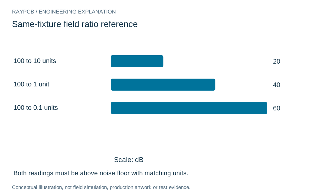
For matching field magnitudes measured with and without the shield, attenuation is 20log10(before/after). A reduction from 100 units to 1 unit corresponds to 40dB. The same field component, unit, geometry and frequency must be used.
Both readings must be above the measurement noise floor and within instrument range. The worksheet leaves negative attenuation visible if the field increases. It does not infer that the material is defective or certify that the product meets an external limit.
Connect the material to the actual enclosure
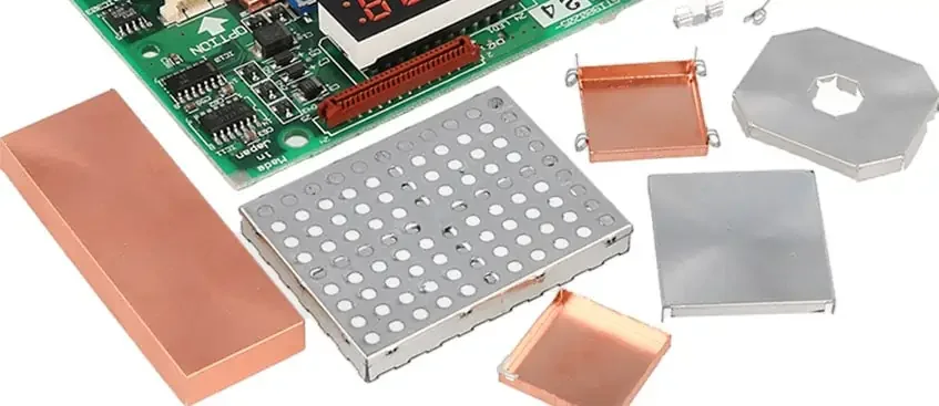
Review apertures, seams, ventilation, connectors and penetrations. A small electrically significant discontinuity can dominate the result despite substantial bulk metal. Board-level shields also need their actual frame, lid and ground connections.
Use high-frequency shielding for electrical-size and opening questions. The wavelength reference on that page helps establish scale without inventing a universal safe aperture dimension.
Compare cost with a defined scope
The optional budget adds your entered recurring, tooling, process and verification allowances. Define whether it includes forming, coating, gasket, soldering, inspection and any qualification work. Keep quantity and construction consistent across candidates.
No market price or supplier availability is embedded in the worksheet. A cheaper raw material may require a different assembly or verification process, so the useful comparison is the delivered construction with the agreed evidence.
Prepare a material and assembly brief
Provide the field problem, frequency range, mechanical envelope, attachment method, environment and acceptance approach. Include exact candidate grades and supplier data rather than only a brand family. Mark unverified substitutions explicitly.
For RAYPCB, identify the board or assembly interface that requires review. Archive photographs on this page illustrate physical forms; they do not prove a specific attenuation, material grade or current factory capability.
Qualify the installed shield, not only the material
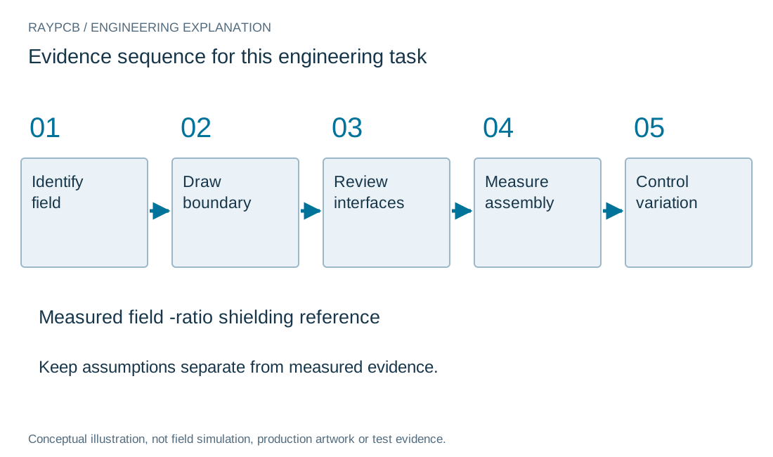
Begin with the field type, frequency range, geometry and required attenuation at a defined measurement point. Conductivity, permeability and material thickness provide part of the picture. Joints, apertures, seams, penetrations and attachment methods can dominate the installed result.
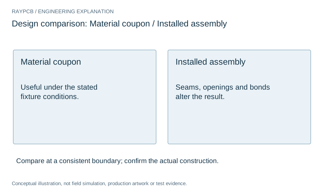
Document the exact foil, cover, gasket, coating or magnetic alloy and its condition. Include the adhesive or surface finish where it forms part of the electrical contact. Do not treat a material coupon rating as a guaranteed result for a populated enclosure with cable openings and removable lids.
Build the comparison around a repeatable fixture and operating state. Record polarization or field orientation, source position, receiver position, dynamic range and the noise floor. If the measured field approaches that floor, report a bound or measurement limitation instead of inventing additional attenuation digits.
Turn the design decision into a controlled record. Keep the schematic and layout revision, model source, operating case and requirement together. Distinguish an entered assumption from a supplier nominal value and a measured result. If an important value is missing, record the unresolved question rather than replacing it with a convenient typical number.
Compare alternatives at a consistent boundary. Preserve the baseline and change one relevant variable when possible. If several features change together, describe the outcome as a comparison between configurations; do not assign the entire improvement to the one component you wanted to justify. Keep both favorable and unfavorable frequency regions in the evidence.
Before a repeat order, check whether substitutions affect the reasoning. A package change, alternate dielectric, shield finish or assembly operation can invalidate an earlier comparison even when the visible board outline is unchanged. Specify which changes need engineering review and which are already accepted. This makes the purchasing and manufacturing handoff useful without asking either team to reconstruct the original electrical investigation.
Standards, source context and limits
Use the applicable device documentation, interface specification and test-method edition for actual requirements. The public sources below explain particular methods; they do not certify the board on this page or replace a licensed standard. Match the document to the selected device, construction and end product before applying a numerical rule.
Numeric examples are teaching inputs unless explicitly identified otherwise. Archive photographs provide physical context, not current factory, customer-project or inspection evidence. Original drawings explain the stated model and are not production artwork, field-solver output or measured waveforms. No search ranking, compliance outcome or manufacturing limit is inferred from these illustrations.
For fabrication scope and the agreed construction requirements, see PCB manufacturing.

