Q: Where can I purchase Xilinx XC2C32A Development Boards, Evaluation Boards, or CoolRunner-II CPLD Starter Kit? also provide technical information?
A: RAYPCB does not provide development board purchase services for the time being, but customers often consult about ZedBoard, Basys 3 board, TinyFPGA BX, Nexys4-DDR, Terasic DE10-Nano, Digilent Arty S7, etc. If you need relevant technical information, you can submit feedback information, our technicians will contact you soon.
Q: Do I have to sign up on the website to make an inquiry for XC2C32A-6QFG32I?
A: No, only submit the quantity, email address and other contact information required for the inquiry of XC2C32A-6QFG32I, but you need to sign up for the post comments and resource downloads.
Q: What should I do if I did not receive the technical support for XC2C32A6QFG32I in time?
A: Depending on the time difference between your location and our location, it may take several hours for us to reply, please be patient, our FPGA technical engineer will help you with the XC2C32A-6QFG32I pinout information, replacement, datasheet in pdf, programming tools, starter kit, etc.
Q: Does the price of XC2C32A-6QFG32I devices fluctuate frequently?
A: The RAYPCB search engine monitors the XC2C32A-6QFG32I inventory quantity and price of global electronic component suppliers in real time, and regularly records historical price data. You can view the historical price trends of electronic components to provide a basis for your purchasing decisions.
Q: How to obtain XC2C32A-6QFG32I technical support documents?
A: Enter the “XC2C32A-6QFG32I” keyword in the search box of the website, or find these through the Download Channel or FPGA Forum .
Q: How can I obtain software development tools related to the Xilinx FPGA platform?
A: In FPGA/CPLD design tools, Xilinx’s Vivado Design Suite is easy to use, it is very user-friendly in synthesis and implementation, and it is easier to use than ISE design tools; The specific choice depends on personal habits and functional requirements to specifically select a more suitable match. You can search and download through the FPGA resource channel.
Xilinx XC2C32A-6QFG32I Features
• In-System Programmable PROMs for Configuration of Xilinx FPGAs
Request Xilinx XC2C32A-6QFG32I FPGA Quote, Pls Send Email to Sales@raypcb.com Now
Xilinx XC2C32A-6QFG32I Overview
This XC2C32A-6QFG32I device consists of eight Function Blocks inter-connected by a low power Advanced Interconnect Matrix (AIM). The AIM feeds 40 true and complement inputs to each Function Block. The Function Blocks consist of a 40 by 56 P-term PLA and 16 macrocells which contain numerous configuration bits that allow for combinational or registered modes of operation.Additionally, these registers can be globally reset or preset and configured as a D or T flip-flop or as a D latch. There are also multiple clock signals, both global and local product term types, configured on a per macrocell basis. Output pin configurations include slew rate limit, bus hold, pull-up, open drain and programmable grounds. A Schmitt-trigger input is available on a per input pin basis. In addition to storing macrocell output states, the macrocell registers may be configured as direct input registers to store signals directly from input pins.Clocking is available on a global or Function Block basis. Three global clocks are available for all Function Blocks as a synchronous clock source. Macrocell registers can be individually configured to power up to the zero or one state. A global set/reset control line is also available to asynchronously set or reset selected registers during operation. Additional local clock, synchronous clock-enable, asynchronous set/reset and output enable signals can be formed using product terms on a per-macrocell or per-Function Block basis.A DualEDGE flip-flop feature is also available on a per macrocell basis. This feature allows high performance synchronous operation based on lower frequency clocking to help reduce the total power consumption of the device.Circuitry has also been included to divide one externally supplied global clock (GCK2) by eight different selections. This yields divide by even and odd clock frequencies.The XC2C32A-6QFG32I CPLD is I/O compatible with various JEDEC I/O standards (see Table 1). This XC2C32A-6QFG32I device is also 1.5V I/O compatible with the use of Schmitt-trigger inputs.By mapping a signal to the DataGATE function, lower power can be achieved due to reduction in signal switching.Another feature that eases voltage translation is I/O banking. Two I/O banks are available on the CoolRunner-II 128 macrocell XC2C32A-6QFG32I device that permit easy interfacing to 3.3V, 2.5V, 1.8V, and 1.5V devices.
The Xilinx tubes series XC2C32A-6QFG32I is CPLD CoolRunner -II Family 750 Gates 32 Macro Cells 200MHz 0.18um (CMOS) Technology 1.8V , View Substitutes & Alternatives along with datasheets, stock, pricing from Authorized Distributors at RAYPCB.com,
and you can also search for other FPGAs products.
Xilinx XC2C32A-6QFG32I Tags
1. Xilinx CoolRunner-II CPLD development board
2. XC2C32A reference design
3. CoolRunner-II CPLD starter kit
4. XC2C32A-6QFG32I Datasheet PDF
5. XC2C32A evaluation board
6. CoolRunner-II CPLD evaluation kit
7. CoolRunner-II CPLD XC2C32A
8. XC2C32A development board
9. XC2C32A-6QFG32I Datasheet PDF
Xilinx XC2C32A-6QFG32I TechnicalAttributes
-Number of Macrocells 32
-Supplier Device Package 32-QFN (5×5)
-Mounting Type Surface Mount
-Package / Case 32-VFQFN Exposed Pad
-Delay Time tpd(1) Max 5.5ns
-Operating Temperature -40℃ ~ 85℃ (TA)
-Number of Logic Elements/Blocks 2
-Voltage Supply – Internal 1.7V ~ 1.9V
-Number of I/O 21
-Programmable Type In System Programmable
Q: How to obtain XC2C32A-6CP56I technical support documents?
A: Enter the “XC2C32A-6CP56I” keyword in the search box of the website, or find these through the Download Channel or FPGA Forum .
Q: Do I have to sign up on the website to make an inquiry for XC2C32A-6CP56I?
A: No, only submit the quantity, email address and other contact information required for the inquiry of XC2C32A-6CP56I, but you need to sign up for the post comments and resource downloads.
Q: How can I obtain software development tools related to the Xilinx FPGA platform?
A: In FPGA/CPLD design tools, Xilinx’s Vivado Design Suite is easy to use, it is very user-friendly in synthesis and implementation, and it is easier to use than ISE design tools; The specific choice depends on personal habits and functional requirements to specifically select a more suitable match. You can search and download through the FPGA resource channel.
Q: Does the price of XC2C32A-6CP56I devices fluctuate frequently?
A: The RAYPCB search engine monitors the XC2C32A-6CP56I inventory quantity and price of global electronic component suppliers in real time, and regularly records historical price data. You can view the historical price trends of electronic components to provide a basis for your purchasing decisions.
Q: Where can I purchase Xilinx XC2C32A Development Boards, Evaluation Boards, or CoolRunner-II CPLD Starter Kit? also provide technical information?
A: RAYPCB does not provide development board purchase services for the time being, but customers often consult about ZedBoard, Basys 3 board, TinyFPGA BX, Nexys4-DDR, Terasic DE10-Nano, Digilent Arty S7, etc. If you need relevant technical information, you can submit feedback information, our technicians will contact you soon.
Q: What should I do if I did not receive the technical support for XC2C32A6CP56I in time?
A: Depending on the time difference between your location and our location, it may take several hours for us to reply, please be patient, our FPGA technical engineer will help you with the XC2C32A-6CP56I pinout information, replacement, datasheet in pdf, programming tools, starter kit, etc.
Xilinx XC2C32A-6CP56I Features
• In-System Programmable PROMs for Configuration of Xilinx FPGAs
Request Xilinx XC2C32A-6CP56I FPGA Quote, Pls Send Email to Sales@raypcb.com Now
Xilinx XC2C32A-6CP56I Overview
This XC2C32A-6CP56I device consists of eight Function Blocks inter-connected by a low power Advanced Interconnect Matrix (AIM). The AIM feeds 40 true and complement inputs to each Function Block. The Function Blocks consist of a 40 by 56 P-term PLA and 16 macrocells which contain numerous configuration bits that allow for combinational or registered modes of operation.Additionally, these registers can be globally reset or preset and configured as a D or T flip-flop or as a D latch. There are also multiple clock signals, both global and local product term types, configured on a per macrocell basis. Output pin configurations include slew rate limit, bus hold, pull-up, open drain and programmable grounds. A Schmitt-trigger input is available on a per input pin basis. In addition to storing macrocell output states, the macrocell registers may be configured as direct input registers to store signals directly from input pins.Clocking is available on a global or Function Block basis. Three global clocks are available for all Function Blocks as a synchronous clock source. Macrocell registers can be individually configured to power up to the zero or one state. A global set/reset control line is also available to asynchronously set or reset selected registers during operation. Additional local clock, synchronous clock-enable, asynchronous set/reset and output enable signals can be formed using product terms on a per-macrocell or per-Function Block basis.A DualEDGE flip-flop feature is also available on a per macrocell basis. This feature allows high performance synchronous operation based on lower frequency clocking to help reduce the total power consumption of the device.Circuitry has also been included to divide one externally supplied global clock (GCK2) by eight different selections. This yields divide by even and odd clock frequencies.The XC2C32A-6CP56I CPLD is I/O compatible with various JEDEC I/O standards (see Table 1). This XC2C32A-6CP56I device is also 1.5V I/O compatible with the use of Schmitt-trigger inputs.By mapping a signal to the DataGATE function, lower power can be achieved due to reduction in signal switching.Another feature that eases voltage translation is I/O banking. Two I/O banks are available on the CoolRunner-II 128 macrocell XC2C32A-6CP56I device that permit easy interfacing to 3.3V, 2.5V, 1.8V, and 1.5V devices.
The Xilinx CPLDs series XC2C32A-6CP56I is 32 MACROCELL 1.8V ZERO POWER ISP CPLD, View Substitutes & Alternatives along with datasheets, stock, pricing from Authorized Distributors at RAYPCB.com,
and you can also search for other FPGAs products.
-Programmable Type In System Programmable
-Number of Logic Elements/Blocks 2
-Number of I/O 33
-Number of Macrocells 32
-Number of Gates 750
-Supplier Device Package 56-CSBGA (6×6)
-Delay Time tpd(1) Max 5.5ns
-Package / Case 56-LFBGA, CSPBGA
-Operating Temperature -40℃ ~ 85℃ (TA)
-Voltage Supply – Internal 1.7V ~ 1.9V
Q: How can I obtain software development tools related to the Xilinx FPGA platform?
A: In FPGA/CPLD design tools, Xilinx’s Vivado Design Suite is easy to use, it is very user-friendly in synthesis and implementation, and it is easier to use than ISE design tools; The specific choice depends on personal habits and functional requirements to specifically select a more suitable match. You can search and download through the FPGA resource channel.
Q: How to obtain XC2C256-7VQG100I technical support documents?
A: Enter the “XC2C256-7VQG100I” keyword in the search box of the website, or find these through the Download Channel or FPGA Forum .
Q: Does the price of XC2C256-7VQG100I devices fluctuate frequently?
A: The RAYPCB search engine monitors the XC2C256-7VQG100I inventory quantity and price of global electronic component suppliers in real time, and regularly records historical price data. You can view the historical price trends of electronic components to provide a basis for your purchasing decisions.
Q: What should I do if I did not receive the technical support for XC2C2567VQG100I in time?
A: Depending on the time difference between your location and our location, it may take several hours for us to reply, please be patient, our FPGA technical engineer will help you with the XC2C256-7VQG100I pinout information, replacement, datasheet in pdf, programming tools, starter kit, etc.
Q: Do I have to sign up on the website to make an inquiry for XC2C256-7VQG100I?
A: No, only submit the quantity, email address and other contact information required for the inquiry of XC2C256-7VQG100I, but you need to sign up for the post comments and resource downloads.
Q: Where can I purchase Xilinx XC2C256 Development Boards, Evaluation Boards, or CoolRunner-II CPLD Starter Kit? also provide technical information?
A: RAYPCB does not provide development board purchase services for the time being, but customers often consult about ZedBoard, Basys 3 board, TinyFPGA BX, Nexys4-DDR, Terasic DE10-Nano, Digilent Arty S7, etc. If you need relevant technical information, you can submit feedback information, our technicians will contact you soon.
Xilinx XC2C256-7VQG100I Features
– As fast as 5.7 ns pin-to-pin delays
– Optimized architecture for effective logic synthesis. Refer to the CoolRunner-II family data sheet for architecture description.
– As low as 13 μA quiescent current
– Multi-voltage I/O operation — 1.5V to 3.3V
• Available in multiple package options
• Industry’s best 0.18 micron CMOS CPLD
– Pb-free available for all packages
• Optimized for 1.8V systems
– 100-pin VQFP with 80 user I/O
– 256-ball FT (1.0mm) BGA with 184 user I/O
– 132-ball CP (0.5mm) BGA with 106 user I/O
– 144-pin TQFP with 118 user I/O
– 208-pin PQFP with 173 user I/O
Request Xilinx XC2C256-7VQG100I FPGA Quote, Pls Send Email to Sales@raypcb.com Now
Xilinx XC2C256-7VQG100I Overview
The CoolRunner-II 128 macrocell CPLD is I/O compatible with various JEDEC I/O standards (see Table 1). This XC2C256-7VQG100I device is also 1.5V I/O compatible with the use of Schmitt-trigger inputs. The XC2C256-7VQG100I device is designed for both high performance and low power applications. This lends power savings to high-end communication equipment and high speed to battery operated devices. Due to the low power stand-by and dynamic operation, overall system reliability is improved
This XC2C256-7VQG100I device consists of eight Function Blocks inter-connected by a low power Advanced Interconnect Matrix (AIM). The AIM feeds 40 true and complement inputs to each Function Block. The Function Blocks consist of a 40 by 56 P-term PLA and 16 macrocells which contain numerous configuration bits that allow for combinational or registered modes of operation.
Additionally, these registers can be globally reset or preset and configured as a D or T flip-flop or as a D latch. There are also multiple clock signals, both global and local product term types, configured on a per macrocell basis. Output pin configurations include slew rate limit, bus hold, pull-up, open drain and programmable grounds. A Schmitt-trigger input is available on a per input pin basis. In addition to storing macrocell output states, the macrocell registers may be configured as direct input registers to store signals directly from input pins.
Clocking is available on a global or Function Block basis. Three global clocks are available for all Function Blocks as a synchronous clock source. Macrocell registers can be individually configured to power up to the zero or one state. A global set/reset control line is also available to asynchronously set or reset selected registers during operation. Additional local clock, synchronous clock-enable, asynchronous set/reset and output enable signals can be formed using product terms on a per-macrocell or per-Function Block basis.
A DualEDGE flip-flop feature is also available on a per macrocell basis. This feature allows high performance synchronous operation based on lower frequency clocking to help reduce the total power consumption of the XC2C256-7VQG100I device.
Circuitry has also been included to divide one externally supplied global clock (GCK2) by eight different selections. This yields divide by even and odd clock frequencies.
The use of the clock divide (division by 2) and DualEDGE flip-flop gives the resultant CoolCLOCK feature
DataGATE is a method to selectively disable inputs of the CPLD that are not of interest during certain points in time.
By mapping a signal to the DataGATE function, lower power can be achieved due to reduction in signal switching.
Another feature that eases voltage translation is I/O banking. Two I/O banks are available on the XC2C256-7VQG100I device that permit easy interfacing to 3.3V, 2.5V, 1.8V, and 1.5V devices.
The Xilinx CPLDs series XC2C256-7VQG100I is 256 MACROCELL 1.8V ZERO POWER ISP CPLD, View Substitutes & Alternatives along with datasheets, stock, pricing from Authorized Distributors at RAYPCB.com,
and you can also search for other FPGAs products.
Q: How can I obtain software development tools related to the Xilinx FPGA platform?
A: In FPGA/CPLD design tools, Xilinx’s Vivado Design Suite is easy to use, it is very user-friendly in synthesis and implementation, and it is easier to use than ISE design tools; The specific choice depends on personal habits and functional requirements to specifically select a more suitable match. You can search and download through the FPGA resource channel.
Q: Does the price of XC2C128-7VQG100C devices fluctuate frequently?
A: The RAYPCB search engine monitors the XC2C128-7VQG100C inventory quantity and price of global electronic component suppliers in real time, and regularly records historical price data. You can view the historical price trends of electronic components to provide a basis for your purchasing decisions.
Q: Where can I purchase Xilinx XC2C128 Development Boards, Evaluation Boards, or CoolRunner-II CPLD Starter Kit? also provide technical information?
A: RAYPCB does not provide development board purchase services for the time being, but customers often consult about ZedBoard, Basys 3 board, TinyFPGA BX, Nexys4-DDR, Terasic DE10-Nano, Digilent Arty S7, etc. If you need relevant technical information, you can submit feedback information, our technicians will contact you soon.
Q: What should I do if I did not receive the technical support for XC2C1287VQG100C in time?
A: Depending on the time difference between your location and our location, it may take several hours for us to reply, please be patient, our FPGA technical engineer will help you with the XC2C128-7VQG100C pinout information, replacement, datasheet in pdf, programming tools, starter kit, etc.
Q: Do I have to sign up on the website to make an inquiry for XC2C128-7VQG100C?
A: No, only submit the quantity, email address and other contact information required for the inquiry of XC2C128-7VQG100C, but you need to sign up for the post comments and resource downloads.
Q: How to obtain XC2C128-7VQG100C technical support documents?
A: Enter the “XC2C128-7VQG100C” keyword in the search box of the website, or find these through the Download Channel or FPGA Forum .
Xilinx XC2C128-7VQG100C Features
• Endurance of 20,000 Program/Erase Cycles
Request Xilinx XC2C128-7VQG100C FPGA Quote, Pls Send Email to Sales@raypcb.com Now
Xilinx XC2C128-7VQG100C Overview
The CoolRunner-II 128-macrocell device is designed for both high performance and low power applications. This lends power savings to high-end communication equipment and high speed to battery operated devices. Due to the low power stand-by and dynamic operation, overall system reliability is improvedThis device consists of eight Function Blocks inter-connected by a low power Advanced Interconnect Matrix (AIM). The AIM feeds 40 true and complement inputs to each Function Block. The Function Blocks consist of a 40 by 56 P-term PLA and 16 macrocells which contain numerous configuration bits that allow for combinational or registered modes of operation.Additionally, these registers can be globally reset or preset and configured as a D or T flip-flop or as a D latch. There are also multiple clock signals, both global and local product term types, configured on a per macrocell basis. Output pin configurations include slew rate limit, bus hold, pull-up, open drain and programmable grounds. A Schmitt-trigger input is available on a per input pin basis. In addition to storing macrocell output states, the macrocell registers may be configured as direct input registers to store signals directly from input pins.Clocking is available on a global or Function Block basis. Three global clocks are available for all Function Blocks as a synchronous clock source. Macrocell registers can be individually configured to power up to the zero or one state. A global set/reset control line is also available to asynchronously set or reset selected registers during operation. Additional local clock, synchronous clock-enable, asynchronous set/reset and output enable signals can be formed using product terms on a per-macrocell or per-Function Block basis.A DualEDGE flip-flop feature is also available on a per macrocell basis. This feature allows high performance synchronous operation based on lower frequency clocking to help reduce the total power consumption of the device.Circuitry has also been included to divide one externally supplied global clock (GCK2) by eight different selections. This yields divide by even and odd clock frequencies.The use of the clock divide (division by 2) and DualEDGE flip-flop gives the resultant CoolCLOCK featureDataGATE is a method to selectively disable inputs of the CPLD that are not of interest during certain points in time.By mapping a signal to the DataGATE function, lower power can be achieved due to reduction in signal switching.Another feature that eases voltage translation is I/O banking. Two I/O banks are available on the CoolRunner-II 128 macrocell device that permit easy interfacing to 3.3V, 2.5V, 1.8V, and 1.5V devices.The CoolRunner-II 128 macrocell CPLD is I/O compatible with various JEDEC I/O standards (see Table 1). This device is also 1.5V I/O compatible with the use of Schmitt-trigger inputs.Table 1: I/O Standards for XC2C128(1)IOSTANDARD AttributeOutput VCCIOInput VCCIOInput VREFBoard Termination Voltage VTTLVTTL3.33.3N/AN/ALVCMOS333.33.3N/AN/ALVCMOS252.52.5N/AN/ALVCMOS181.81.8N/AN/ALVCMOS15(2)1.51.5N/AN/AHSTL_11.51.50.750.75SSTL2_12.52.51.251.25SSTL3_13.33.31.51.5
The Xilinx Embedded – CPLDs (Complex Programmable Logic Devices) series XC2C128-7VQG100C is CPLD CoolRunner -II Family 3K Gates 128 Macro Cells 152MHz 0.18um (CMOS) Technology 1.8V, View Substitutes & Alternatives along with datasheets, stock, pricing from Authorized Distributors at RAYPCB.com,
and you can also search for other FPGAs products.
-Package / Case 100-TQFP
-Voltage Supply – Internal 1.7V ~ 1.9V
-Number of Gates 3000
-Number of Logic Elements/Blocks 8
-Delay Time tpd(1) Max 7.0ns
-Number of I/O 80
-Programmable Type In System Programmable
-Supplier Device Package 100-VQFP (14×14)
-Mounting Type Surface Mount
-Number of Macrocells 128
Q: What should I do if I did not receive the technical support for XC2C1287VQ100C in time?
A: Depending on the time difference between your location and our location, it may take several hours for us to reply, please be patient, our FPGA technical engineer will help you with the XC2C128-7VQ100C pinout information, replacement, datasheet in pdf, programming tools, starter kit, etc.
Q: Where can I purchase Xilinx XC2C128 Development Boards, Evaluation Boards, or CoolRunner-II CPLD Starter Kit? also provide technical information?
A: RAYPCB does not provide development board purchase services for the time being, but customers often consult about ZedBoard, Basys 3 board, TinyFPGA BX, Nexys4-DDR, Terasic DE10-Nano, Digilent Arty S7, etc. If you need relevant technical information, you can submit feedback information, our technicians will contact you soon.
Q: How can I obtain software development tools related to the Xilinx FPGA platform?
A: In FPGA/CPLD design tools, Xilinx’s Vivado Design Suite is easy to use, it is very user-friendly in synthesis and implementation, and it is easier to use than ISE design tools; The specific choice depends on personal habits and functional requirements to specifically select a more suitable match. You can search and download through the FPGA resource channel.
Q: How to obtain XC2C128-7VQ100C technical support documents?
A: Enter the “XC2C128-7VQ100C” keyword in the search box of the website, or find these through the Download Channel or FPGA Forum .
Q: Do I have to sign up on the website to make an inquiry for XC2C128-7VQ100C?
A: No, only submit the quantity, email address and other contact information required for the inquiry of XC2C128-7VQ100C, but you need to sign up for the post comments and resource downloads.
Q: Does the price of XC2C128-7VQ100C devices fluctuate frequently?
A: The RAYPCB search engine monitors the XC2C128-7VQ100C inventory quantity and price of global electronic component suppliers in real time, and regularly records historical price data. You can view the historical price trends of electronic components to provide a basis for your purchasing decisions.
Xilinx XC2C128-7VQ100C Features
• Endurance of 20,000 Program/Erase Cycles
Request Xilinx XC2C128-7VQ100C FPGA Quote, Pls Send Email to Sales@raypcb.com Now
Xilinx XC2C128-7VQ100C Overview
The CoolRunner-II 128-macrocell device is designed for both high performance and low power applications. This lends power savings to high-end communication equipment and high speed to battery operated devices. Due to the low power stand-by and dynamic operation, overall system reliability is improvedThis device consists of eight Function Blocks inter-connected by a low power Advanced Interconnect Matrix (AIM). The AIM feeds 40 true and complement inputs to each Function Block. The Function Blocks consist of a 40 by 56 P-term PLA and 16 macrocells which contain numerous configuration bits that allow for combinational or registered modes of operation.Additionally, these registers can be globally reset or preset and configured as a D or T flip-flop or as a D latch. There are also multiple clock signals, both global and local product term types, configured on a per macrocell basis. Output pin configurations include slew rate limit, bus hold, pull-up, open drain and programmable grounds. A Schmitt-trigger input is available on a per input pin basis. In addition to storing macrocell output states, the macrocell registers may be configured as direct input registers to store signals directly from input pins.Clocking is available on a global or Function Block basis. Three global clocks are available for all Function Blocks as a synchronous clock source. Macrocell registers can be individually configured to power up to the zero or one state. A global set/reset control line is also available to asynchronously set or reset selected registers during operation. Additional local clock, synchronous clock-enable, asynchronous set/reset and output enable signals can be formed using product terms on a per-macrocell or per-Function Block basis.A DualEDGE flip-flop feature is also available on a per macrocell basis. This feature allows high performance synchronous operation based on lower frequency clocking to help reduce the total power consumption of the device.Circuitry has also been included to divide one externally supplied global clock (GCK2) by eight different selections. This yields divide by even and odd clock frequencies.The use of the clock divide (division by 2) and DualEDGE flip-flop gives the resultant CoolCLOCK featureDataGATE is a method to selectively disable inputs of the CPLD that are not of interest during certain points in time.By mapping a signal to the DataGATE function, lower power can be achieved due to reduction in signal switching.Another feature that eases voltage translation is I/O banking. Two I/O banks are available on the CoolRunner-II 128 macrocell device that permit easy interfacing to 3.3V, 2.5V, 1.8V, and 1.5V devices.The CoolRunner-II 128 macrocell CPLD is I/O compatible with various JEDEC I/O standards (see Table 1). This device is also 1.5V I/O compatible with the use of Schmitt-trigger inputs.Table 1: I/O Standards for XC2C128(1)IOSTANDARD AttributeOutput VCCIOInput VCCIOInput VREFBoard Termination Voltage VTTLVTTL3.33.3N/AN/ALVCMOS333.33.3N/AN/ALVCMOS252.52.5N/AN/ALVCMOS181.81.8N/AN/ALVCMOS15(2)1.51.5N/AN/AHSTL_11.51.50.750.75SSTL2_12.52.51.251.25SSTL3_13.33.31.51.5
The Xilinx CPLDs series XC2C128-7VQ100C is 128 MACROCELL 1.8V ZERO POWER ISP CPLD, View Substitutes & Alternatives along with datasheets, stock, pricing from Authorized Distributors at RAYPCB.com,
and you can also search for other FPGAs products.
-Programmable Type In System Programmable
-Supplier Device Package 100-VQFP (14×14)
-Number of Gates 3000
-Delay Time tpd(1) Max 7.0ns
-Voltage Supply – Internal 1.7V ~ 1.9V
-Mounting Type Surface Mount
-Number of Logic Elements/Blocks 8
-Package / Case 100-TQFP
-Number of Macrocells 128
-Operating Temperature 0℃ ~ 70℃ (TA)
A multilayer ceramic capacitor is a capacitor made up of multiple layers of ceramic material. We can use this capacitor for various applications, including telecommunications, audio, and video. It is also applicable in RF designs, where low losses are necessary. Its electrodes can be either base metals or precious metals. The electrode materials used can affect the capacitor’s performance. Palladium, for example, is commonly used in RF designs because it can tolerate high temperatures and achieve full densification.
The MLCC is an electronic component that serves a coupling capacitor’s role. This type of capacitance is usually used in electronic circuits when it is necessary to have a good frequency response over the entire range of frequencies. An MLCC can be polarized or unpolarized, depending on requirements.
Multilayer ceramic capacitors were developed by stacking multiple ceramic discs into a monolithic block. A company in the US pioneered this process and was much cheaper to manufacture than ceramic tube capacitors. In addition, it allowed for high capacitance and was compact. As a result, it significantly improved ceramic tube capacitors and increased the number of applications they could serve. These new capacitors were instrumental in shifting electronic devices from through-hole to surface-mount technology during the 1980s.
An MLCC consists of several alternating conductive and dielectric layers. You make these capacitors with many thin sheets stacked together with insulating layers between each.
Multilayer ceramic capacitors are common in electronic equipment. Dielectric directly affects the performance of MLCCs. Dielectric is falls into two classes, Class 1 and Class 2. Class 1 capacitors have the best accuracy and stability, while Class 2 capacitors have lower accuracy and volumetric efficiency. Class 1 ceramic capacitors are good for high-voltage applications, while class 2 are primarily good for low-frequency, high-volume applications.
An MLCC consists of multiple layers of ceramic material with conductive electrodes sandwiched between them. These layers are bonded together via terminal surfaces. You can use conductive wires to connect the electrodes to the ceramic layers.
Multilayer ceramic capacitors are a critical component in many electronic devices, enabling high performance, multifunctionality, and high integration. MLCCs are examples of recent advances in high-capacitance ceramic materials.
We can also use these components as resistors, diodes and voltage regulators. You will find them in circuits as high-frequency chip capacitors.
Others include:
Class 2 MLCC
A Class 2 multilayer ceramic capacitor (MLCC) is a device with a multilayer structure. These devices are used in many electronic applications and can operate at extreme temperatures. An MLCC’s ohmic losses are measured using a formula known as equivalent series resistance (ESR). Effective self-inductance is the effective self-inductance of the capacitor. This formula is defined in IEC/EN 60384-1.
Y5V class 2 MLCC
Y5V multilayer ceramic capacitors are a good choice for many applications. They can operate at a wide range of temperatures, from -30 to +85 degrees Celsius. Their capacitance is not more than 82% of the nominal value. They are available in many dielectric types, including X7R, C0G, and X7S.
We make the Y5V MLCC using thin dielectric layers stacked in series. This design is suitable for bulk capacitance applications and characterized by a small footprint. It offers high capacitance, but at the same time has a low temperature dependence. You can use this ceramic capacitor in many applications, from low-frequency to high-frequency.
Y5V class 4 MLCC
The Y5V class 4 multilayer ceramic multilayer capacitor is a good choice for applications that require high capacitance and low self-discharge rate. Its dielectric properties have high permeability, low absorption, and high capacitance. The data sheet does not specify its resistance or its magnitude, but it does list the impedance. The impedance is a measurement of the resistance of a ceramic capacitor to alternating current. The lower the impedance, the higher the capacitance, but the higher the impedance, the less capacitance it can offer.
Y5V class 5 MLCC
A Y5V class 5 multilayer ceramic (MLCC) has a sensitivity to temperature of +85 C. This temperature range is sufficient for devices that operate at room temperature. In addition, a Y5V class 5 capacitor is suitable for devices that require high capacitance. The following table gives you an overview of the characteristics of this type of capacitor.
Y5V class 6 MLCC
A multilayer ceramic capacitor has thin dielectric layers and a small footprint. Their low impedance allows more alternating current to flow through them. Their impedance is proportional to 1/t1x(t1+t2), where t1 and t2 are the dielectric and electrode thicknesses, respectively. These capacitors are available in various capacitance values.
Y5V class 7 MLCC
You can make Y5V class 7 multilayer ceramics by combining thin ceramic layers with a binder. First, we roll up the resulting thin film for ease of transport. Once rolled, you can cut the ceramic sheet into equal-sized sheets and screen printed with metal paste. These sheets become the electrodes of the capacitor. You then stack the electrodes atop the other in several layers, determining the capacitance. Finally, connect the electrodes in parallel and offset from one another, with the corresponding offset sides connecting to each other.
We can use a Y5V class 8 multilayer ceramic (MLCC) capacitor to improve consumer electronics’ power density and energy storage efficiency. You can make these devices using thin ceramic foil coated with a binder. The foil is then cut into equal-sized sheets and screen-printed with a metal paste to create electrodes. You then stack the electrodes in the required number of layers, which determines the capacitance value. Finally, connect the electrodes on the offset side of the adjacent layers.
The capacitance of multilayer ceramic capacitors depends on the application. For example, high-end class 1 capacitors have a narrow tolerance and use them in precision timers and oscillators. On the other hand, we use class 2 ceramic capacitors in non-critical filtering and coupling applications. However, they have a lower tolerance than their counterparts and are more expensive. Another important consideration when selecting a multilayer ceramic capacitor is its temperature coefficient. While ceramic capacitor capacitance increases with temperature, its temperature coefficient varies across different types. We express this in parts-per-million and percentage over a wide temperature range.
A clear understanding of MLCCs
Multilayer ceramic capacitors have a large range of applications. The material’s electrical properties and sensitivity to temperature affect their performance. Ceramic capacitors vary in their capacitance with temperature.
The capacitance of an MLCC chip increases with the thickness of the dielectric and the area of the electrode. In addition, a thinner dielectric material has a higher permittivity. In addition to its low mounting inductance, the X2Y footprint is especially useful in high-speed digital circuits, which must decouple supply voltages. Moreover, an X2Y capacitor can replace up to five ceramic capacitors on a PCB. However, these capacitors are not cheap.
Multilayer ceramic capacitors can be used in various applications and are available in different sizes. Their capacitance ranges from 10 pF to 0.1 mF. Their rated voltage is 2V. Therefore, you can mount them on standard surface mount equipment. We manufacture them in full integration manufacturing processes with strict quality control.
How do multilayer ceramic capacitors work?
The basic principle behind multilayer ceramic capacitors is to use multiple layers of dielectric material to store electrical energy. First, make the material into thin foils, then roll and cut into equal-sized sheets. These equal-sized sheets are then screen printed with a metal paste and stacked in an alternating manner. This method allows the capacitor’s electrodes to offset each other. The number of layers determines the capacitor’s total capacitance.
Simply put, an MLCC works by storing charge on its different layers. The layers alternate between high and low capacitance values. The layers of an MLCC are so fine that you can easily store an electrical charge on them.
Generally, the outermost layers of these capacitors have the highest capacitance values. It gives an MLCC its ability to store a large amount of charge, with a relatively small volume of materials.
Multilayer ceramic capacitors are ideal for applications where space is limited and a high capacitance is required. Specifying the dielectric strength of a capacitor and the breakdown voltage is possible. These parameters vary by up to ten times, so high precision is required to maintain their electrical properties within the limits.
The EIA-standardized coding system allows engineers to determine MLCC characteristics and performance. For example, it is easy to interpret and explains the differences between a capacitor’s capacitance and its ohmic losses. In addition, it gives a measurement of the capacitor’s effective self-inductance.
Generally, a ceramic capacitor has a constant voltage rating and a high dielectric constant; its capacitance will decrease with age. A good ohmmeter will show you the value of the capacitor’s capacitance and will help you identify if there are any short circuits or shortened readings. If you are a professional user or a hobbyist, you’ll already be familiar with the ranges of voltages these capacitors work with.
Ceramic capacitors have several layers, each layer containing conductive electrodes. The ceramic material acts as the dielectric between the electrodes and the metal contact surface. An MLCC can have hundreds of layers, each with a similar capacitance.
The dielectric materials we use in constructing these capacitors offer varying degrees of resistance to alternating currents. Each layer, therefore, has a specific capacitance value determined by the alternating layers of dielectric material.
The capacitance of an MLCC is dependent upon its size and configuration. Typically, the higher up a capacitor is in this type of construction, the higher its capacitance value will be.
Benefits for using multilayer ceramic capacitor
Multilayer ceramic capacitors are very effective in enhancing capacitance and reducing their size. Therefore, these capacitors are ideal for high-speed digital circuits where decoupling supply voltages is difficult due to parasitic inductances. However, using them has disadvantages, and one should consider them when designing electronic circuits.
Another benefit of multilayer ceramic capacitors is that they are highly resistant to abnormal voltage. While tantalum and aluminum electrolytic capacitors have a DC breakdown voltage of 30-60 V, multilayer ceramic capacitors can withstand more than 200 V. This feature helps to minimize the risk of a surge voltage or dielectric breakdown in circuits involving semiconductors.
These capacitors have a high dielectric strength and a long market history. Their high stability, low losses, and high volumetric efficiency make them highly desirable. They have a wide range of applications. They are also suitable for high-voltage power applications. Therefore, the demand for MLCCs has increased the demand for their production.
MLCC types can help save energy while they are used in electronic circuits and on electronic devices. They also help trigger the switching of an output circuit to produce a higher voltage at a lower current.
These capacitors can also help filter out unwanted noise as part of an audio or radio circuit. In addition, they can prevent certain types of interference, such as that caused by faulty power sources.
This is especially helpful in several digital circuits and in wireless devices, where eliminating noise is crucial to the performance of these components and the circuits they are designed for.
A final benefit of multilayer ceramic capacitors is that they can help stabilize the voltage level in a circuit. Such is due to the fact that they can undergo polarization, to provide an increased amount of current into a circuit at specific, high frequencies.
Disadvantages of MLCCs
One of the main disadvantages of multilayer ceramic capacitors is their high cost. They are very expensive and are not always suitable for high-speed applications. These capacitors are also susceptible to corrosion and need proper handling. If you don’t handle the capacitor properly, it can lead to a short circuit.
A Multilayer Ceramic Capacitor (MLCC) construction involves using many thin ceramic layers to increase the device’s capacitance. These scalable capacitors allow manufacturers to reduce their total footprint and cost. We can make capacitors in various configurations, such as cylinders, disks, or wafers. Their design will depend on the needs of the application.
The ESR, or equivalent series resistance, is an important property of a ceramic capacitor. It defines its resistance and effective self-inductance. The ESR of a capacitor is never infinite, and varies according to its chemistry and configuration. The lowest impedance is present at the point of resonance, and the highest impedance is at higher frequencies.
The bending strength of an MLCC chip depends on the ceramic used, its size, and the design of the capacitor. For example, NP0/C0G class 1 ceramic MLCC chips can typically reach around two millimeters bending strengths. On the other hand, X7R class two ceramic MLCC chips achieve bending strengths of one millimeter.
The capacitance of a ceramic capacitor varies with temperature. This is a consequence of changes in the dielectric constant and the capacitor’s dimension. There is more concentration of this effect near the transition point. As a result, class I and Class II ceramic capacitors are characterized by low dielectric losses, low Tc C, low rate of aging, and a broad working temperature range.
Typically, the construction of an MLCC is a multi-step process. The first step in making a capacitor is to create dielectric materials. Then, we must cut the materials to the desired chip size. Once the materials are ready, you stack the capacitors on a specialized steel frame. Once the stack is complete, you connect the electrodes in parallel to the dielectric sheets.
The next step in the construction process is to sinter the ceramic and electrode materials. Perform the process carefully, and monitor time-temperature profiles. The sintering process should be regulated to prevent the formation of micro-cracks.
This type of capacitor finds numerous uses in the electronics industry. Yet the primary application for these capacitors is as a coupling device. A coupling capacitor acts to bridge two different circuits together so that they act as one system.
Other uses for MLCCs are as a capacitor that can change the DC voltage frequency. An MLCC can be easily changed from its initial capacity to become polarized to specific frequencies.
These components also use as A/C frequency filters, with a range of frequencies undergoing adjustment through a wide range of capacitance values. The range of frequencies can go from three to six megahertz, depending upon the needs of a particular circuit.
When used like this, MLCCs can also act as a voltage regulator. We do this through their ability to change a high-voltage pulse into a lower voltage, in the order of twenty-five volts.
Besides being used in electronics, these components have found uses in medicine, telecommunications and computer technology. Many smaller electronic devices also use them for their components, such as computers and mobile phones, especially for analogue circuit applications.
Although this is an increasingly common use for MLCCs, we often use these components as coupling capacitors in radio transmitters and receivers. They are applicable in high-quality audio applications.
Other Related Applications of Multilayer Ceramic Capacitors
Another use for this type of capacitor is in reverse bias applications inside a dc amplifier circuit. Here, the capacitance value of the MLCC is changed from high to low values to alter the gain of an amplifier circuit.
These capacitors can also be used as a source for noise suppression in radio receivers and transmitters. Here, a capacitor connected in a parallel circuit with the power supply removes high-frequency noise from transmissions.
The last of the primary uses for MLCCs is in medicine, where they act as defibrillator capacitors. In this application, they are applied in parallel with an electrical device used to control cardiac rhythms. This device uses an amount of electric current to shock the heart to restore normal heart rhythms.
This application of MLCCs enhances the results achieved by defibrillators that use ordinary capacitors, by introducing a very high-level voltage into a circuit.
When working with MLCCs, it is always a good idea to make note of their tolerance to ensure that they are compatible for any given application.
A surface-mount capacitor is an MLCC specially designed for use in circuit boards or on surfaces where the components themselves are mounted on a board or PCB (printed circuit board). These capacitors are usually smaller than their standard counterparts, and they can also handle much higher frequencies than ordinary capacitors.
Using a surface-mount capacitor, we can place more parts on a single board, which can help eliminate the need for additional boards.
They are also able to provide more space for components and circuits. They do this because they are smaller than standard capacitors and are less expensive than radial leaded MLCCs.
You can find the performance specifications and the physical dimensions of surface-mount capacitors under the specifications list on their datasheets.
Radial Leaded Automotive MLCCs
These MLCC types have leads that radiate outward from the capacitor’s body. They have a design you can mount on a PCB, with their leads extending through holes in the board and then soldered to other components on that circuit board.
This is in contrast to surface-mount types, which begin their extension from the body of the capacitor itself. It makes them more difficult to use on PCBs with no through-holes.
These capacitors also have precision features, such as low inductance and a low series resistance. Such features allow them to find usage in high-frequency electronics and other applications.
Some surface-mount capacitors can also be designed to have leads that radiate outward from the capacitor’s body. This makes them similar to radial leaded MLCCs. There are several advantages to using this type of capacitor. These include providing greater amounts of current, fitting into smaller spaces, and potentially enabling easier installation.
Another benefit of this type is that they are comparatively less expensive than many other types of MLCCs. In addition to cost, they also have a longer lifespan over other types of capacitors
They can also handle a greater number of opera things, which can help make them more cost-effective than some other types of capacitors.
Whenever someone uses a capacitor, it is important to be careful with its tolerance levels. For example, voltage tolerance levels are not up to manufacturers’ standards. As a result, they can be inaccurate and may not be able to withstand the voltage levels that they are supposed to.
This is especially true when using electrolytic capacitors. These capacitors are also very sensitive and overvoltage, upside-down voltages and incorrect power can damage them. Therefore, users must always be careful when using these types of capacitors in their applications.
Capacitor Lifetimes
Capacitor lifetimes vary depending on several factors. These include the type of capacitor and its intended use.
The type of temperature level, humidity, and environmental conditions also play a part in the lifespan of MLCCs. For example, we use capacitors for switching applications and are exposed to a wide range of temperatures, humidity, and operating voltages. However, temperature and humidity do not affect the materials for making these capacitors.
When choosing the type and size of the capacitor, it is important to keep in mind how long it will take for the capacitor to reach its normal operating temperature. Capacitors that reach their normal operating temperature very quickly usually have a shorter life expectancy than those which do not.
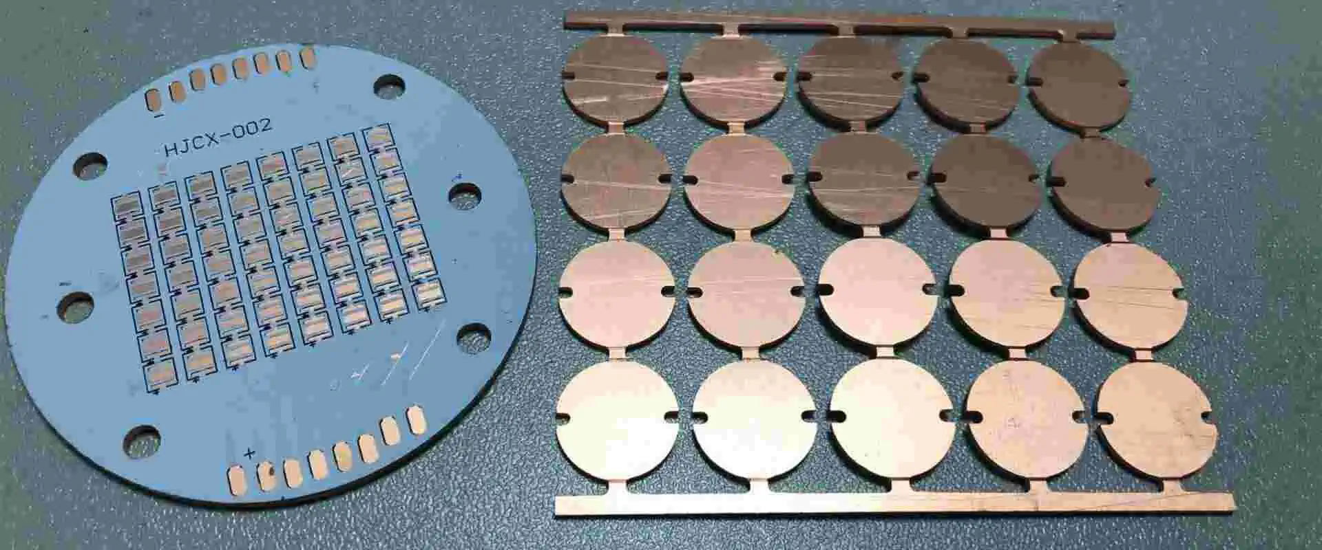
Multilayer metal core PCBs are commonly used in various electronic applications, including communication electronics, power converters, LED boards, LED Based Products, and medical devices. In designing and manufacturing these boards, it is important to pay attention to thermal management and transfer. In addition, one should carefully control the thickness of the boards.
Multilayer metal core PCB is a type of PCB made of metal layers. You press the metal cores during manufacturing and remove the residual filler compounds. You then plate the inner layer cores before preparing the board for lamination. The rest of the process follows the standard manufacturing process.
Multilayer metal core PCB, or MCPCB, is a printed circuit board with a metal core. It has several layers. This circuit board contains a thermal insulating layer made from a metal plate or copper foil. This type of PCB has unique characteristics including good thermal conductivity and heat dissipation. Different types of metal core PCB are available, including copper and aluminum. Copper is the preferred metal for performance but is significantly more expensive. The thickness of this material is usually between 1mm and 4mm.
Metal core PCBs are double-sided, so routing can pass between both sides. In addition, we can use multilayer dielectric stacks on both sides. Despite this, it is important to ensure that you ground the metal layer. This will prevent the metal layer from acting as a big antenna. In addition, some applications may require mourning the metal core to the enclosure.
The outer layers consist of conductive materials and a dielectric layer connects them. This allows for higher flexibility and impedance control. Additionally, these PCBs have reduced EMI shielding and ground layers.
Multilayer metal core PCB differs from conventional FR4 PCBs because it contains a metal layer between two conductive layers. Typically, it consists of two copper conductor layers. Therefore, this PCB requires an additional pressing step to bond the layers together.
Advantages of Multilayer metal core PCB
Multilayer metal core PCBs (MCPCBs) have several advantages over standard FR4 PCBs. They do not require vias for thermal relief and the entire bottom side of the board is made up of metal, making it more efficient thermally. In addition, MCPCBs require little or no drilling and only a few large holes for mounting.
These PCBs have higher thermal conductivity and can handle higher power levels and density. They are typically made from aluminum, which is inexpensive and recyclable. They also transfer heat eight to nine times faster than traditional FR-4 PCBs. Because of the aluminum’s thermal conductivity, the dielectric layer must be very thin, usually between 0.003 and 0.006 inches thick.
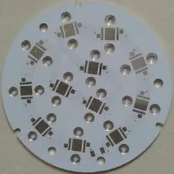
MCPCBs are ideal for applications that produce heat, such as LED lighting systems and power circuits. In addition, they can improve circuit reliability and make components last longer.
This type of board is ideal for circuits with high switching power. It also offers better thermal management than epoxy PCBs. Its thin dielectric layer allows efficient heat transfer, making the metal core less susceptible to cracks. Moreover, metal core PCBs can achieve higher circuit densities than other materials.
A multilayer metal core PCB can be double-sided, allowing routing between both sides. It can also support routing on multiple layers. Ideally, the metal layer should be grounded. This will help prevent the board from acting as a monopole antenna. Depending on the application, mourning the metal core to a protective enclosure may be necessary.
You can also male multilayer PCBs with a single-sided conductive component placement. JLCPCB is equipped with a large library of SMT parts and manufactures them in-house. It also performs automated solder paste placement. In addition, its metal core makes it suitable for applications that require high levels of durability and reliability.
Structure & Base Materials for metal core PCB
We can make multilayer PCBs using three types of base materials. These include aluminum, copper, and stainless steel. Aluminum is the most common metal in use for the base material, while copper is more expensive but has superior thermal conductivity. Both copper and stainless steel have advantages and disadvantages, and you should choose based on your needs. The base material plays an important role in insulating the components. The base material is usually one to four mm thick, depending on customer specifications. Regardless of the material, the base layer is usually the first layer of the PCB.
The base material comes from a thin copper film, which will eventually contain the traces. The upper copper layer is typically between 1 and 4oz thick. The innermost layer is usually a dielectric material, which isolates the metal layer from the copper film and allows for rapid heat transfer. One can make the metal layer from aluminum and is 1.6 to 8mm thick.
Multilayer metal core PCBs are more thermally efficient than traditional PCBs and can handle high power and density circuits. Aluminum is the most common base material, and is inexpensive and recyclable. These boards transfer heat eight to nine times faster than FR-4. Because of their higher conductivity, metal core PCBs require a very thin dielectric layer. The dielectric layer thickness is typically between 0.003 and 0.006 inches.
It is possible to make multilayer metal core PCBs from Copper Invar Copper (CIC) material. The CIC layer contains a nickel-iron alloy sandwiched between two copper layers. It is useful in high-temperature environments to control the expansion of circuits. Additionally, it is good for PCBs with ground planes, power supplies, and metal cores. CIC is in wide use within the aerospace industry.
CIC has a low coefficient of thermal expansion and high thermal conductivity. Therefore, it can be useful as a metal core in PCBs but requires a special etching process. The different etching characteristics of Invar and Cu lead to varying etching rates. In the case of Cu-Invar-copper (CIC), FeCl3 was more effective than CuCl2 in the process.
The metal core is the thickest part of the board. A metal backing plate backs it. Common thicknesses are 1mm, 1.5mm, and 3.2mm. This metal layer helps the circuit remain flat and provides a sufficient thickness for mounting hardware. On the other hand, the exposed metal plate side of the board is not coated with surface finish. This prevents noise from entering the circuit.
Iron-based PCBs
Iron-based multilayer PCBs are those with an iron-based metal core. These PCBs have several layers of conductive material on one side and insulating material on the other. Copper foil and iron are common choices for the conductive layer. Other materials used for the insulating layer include polyester, ceramics, and modified polystyrene ether. Multilayer PCBs require more technology and cost a bit more to produce.
Metal-based multilayer PCBs are generally more robust than their aluminum counterparts. They have lower thermal conductivity than their aluminum counterparts, but are also more expensive and heavier. As a result, they are usually useful in applications where the temperature is extremely high. Another advantage of iron-based PCBs is their ability to dissipate heat from critical components. These PCBs also offer conductive cooling, making them great for high-heat applications.
Metal-based multilayer PCBs are particularly suitable for applications where cooling multiple LEDs is essential. They also offer excellent reliability, and are not prone to bend in extreme temperatures. Their special layers also make them more conductive than FR-4 PCBs.
With the technology industry growing rapidly, consumers demand more accessible and better quality products. Such calls for a wide variety of products from various companies, giving consumers options on what they want to buy. Several components make up an audio system. These include the power amplifier, Speakers, and Phono cartridge spacer. You must understand each one to choose the right one for you. To learn more about audio accessories, read this article.
Our ears deserve the best sound quality. One way to attain that is by investing in audio devices with higher-quality sound output. However, there are several other factors to consider when deciding which device we want. These include how much it will cost us concerning the quality of service we can expect from it and our budget. We also need to know how much usage we can expect from it.
Basically, the higher the quality audio rating, the more money we spend compared to how much usage we can expect from a device. We would want to go for higher-end audio equipment if our budget permits or allows us to afford it. So if our budget allows, we should consider going for a higher quality audio device built to last long and can provide us with lasting value.
The first step would be to determine which manufacturer to go for. Determine this by asking around, checking out reviews, and asking our friends or colleagues who already use that particular brand or model. All these things can help give you the direction you need to select the best audio device for your needs.
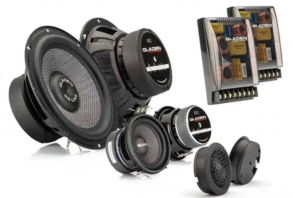
Audio Components are the essential pieces of equipment that reproduce and record sound. They include tape recorders, amplifiers, microphones, speakers, and more. You can also find them in electronic devices, such as CD players and radios. In addition to supplying sound, audio components include headphones and speakers.
Audio components include all the devices that produce and reproduce sound. These include microphones, tape recorders, radio receivers, CD players, mixers, effects units, headphones, speakers, and more. Here is a list of some of the more common types of audio components. All audio equipment consists of one or more of these components.
There are three main types of audio components. These include the pre-amplifier, main amplifier, and speaker. A pre-amplifier is responsible for adjusting the volume, switching the inputs, and setting the gain stage. Although the pre-amplifier’s signal is small, the main amplifier and speakers amplify the distortions it creates. Hence, a higher-quality pre-amp can help the power amp and speakers perform closer to their capability.
The most important component of an audio system is the speaker. It vibrates to produce sound and receives an electrical signal from the playback device. A speaker contains a variety of internal components such as drivers and crossovers. The cabinet of the speaker also determines the quality of the audio. There are also many different types of speakers available in the market.
Picking a Stock Price
Quality is not cheap for everyone, this is obvious. But what about for some? And sure enough, it does not have to be expensive based on individual choice. When we want to consider the basic price of a stock pick, we need to look into what functions are in it, how it is built and other inclusions alongside the purchase. It may be too expensive for some people but others may find it just right. We should first look up the manufacturer’s site, research their product line, and see what they offer us. The only way to determine what they are offering you, is by reading their website. View the online platforms using the HTTPS version.
The most important component of any audio system is the source. Whether you’re listening to music through a cd player, turntable, or record player, the source determines the quality of the music. Audio sources come in many forms, including digital and analog. For example, a receiver with a built-in AM/FM tuner or Wi-Fi can be an external source, as can streaming services.
The source of audio, or head unit, can make or break the overall sound quality of your car system. Audio source components must translate information from digital files into a form suitable for speakers. In addition, the source can affect a variety of other factors, including information retrieval, power delivery, and resolution.
Speakers are an important component of any audio system. They produce sound by vibrating and receive an electrical signal from the playback device. Different speakers have different specifications and are appropriate for different rooms. In addition to acoustics, speakers are also dependent on amplifiers. Done properly, they deliver the desired sound.
Pre-amplifiers are another vital component in an audio system. They help transform audio signals to a level suitable for the power amplifier. The main function of a pre-amp is to improve bass and resolution, and it also controls the gain stage. However, it also helps to prevent phase shifts, leading to distortion and degrading the sound.
Audio components’ functions
Audio components are a key part of a home stereo system. They are crucial in controlling volume, switching inputs, and providing gain. However, without a good pre-amplifier, the sound produced by your speaker system will suffer from distortion. While you can blame the power amp or speakers for distortions, an improved pre-amp can make the signal from your speaker system perform closer to its capability.
Audio component manufacturers produce a variety of products to fit various uses. Some of them are passive while others are active. Active components use energy from power supplies to change the audio signal. On the other hand, passive components do not use any power and we do not expect them to change the signal. Real-world capacitors, resistors, and inductors behave like active components.
The capacitance of an audio component plays an important role in the sound quality. Therefore, use high-quality audio-grade capacitors to minimize signal degradation. Film capacitors are especially popular because of their linearity and are good in top-of-the-line audio equipment. Polypropylene, polyester, and polyphenylene sulfide are common dielectric materials used in audio-grade film capacitors.
Small audio accessories
Audio accessories are small items used to improve the quality of playback. Often, the quality of sound depends on how well the sound equipment can suppress speaker vibration. These accessories are placed under speakers or music players to reduce the vibration. The resulting improvement in sound quality is often very noticeable. However, there are some differences between these accessories and the components in stereo sound systems.
Power amplifier
When you buy a power amplifier, it’s important to understand its specifications. Besides the power consumption, you also need to consider the heatsink and other features. Some of these features are not readily apparent and may be hidden in other specs. For example, operating voltage is very important in a car audio amplifier because these devices do not connect to the car’s mains power supply. They, therefore, use the battery to run. However, car audio amplifiers also need an alternator to prevent the battery from being drained.
The output of an audio power amplifier can range from a few milliwatts in headphone amplifiers to thousands of watts in home theater systems. These devices also apply in wireless transmissions, which require transmitting modulated waves through the air. To ensure that the transmission distance is not compromised, we should rate the amplifier’s power input for the current draw of the speaker.
We classify power amplifiers as Class A, B, and C. Each type has different characteristics. Some of them are more efficient than others. Some of them even require a large static current to operate. While these devices are generally cheap, they may not be as efficient as those designed for a higher-end stereo.
We also classify a power amplifier according to the type of signal it amplifies. They fall into two categories: analog and digital. Class A power amplifiers work on analog signals, while Class B power amplifiers use digital signals. Analog waveforms have highs and lows. A power amplifier uses this waveform to amplify the signal.
Power amplifiers are the final part of the audio chain. The purpose of a power amplifier is to increase the input signal to a certain level to drive a load. They usually include preamplifiers and power amplifiers. They can also include other functions, such as volume adjustment, tone control, and channel equalization. The power rating is an important factor for evaluating the sound quality of a system.
Different types of power amplifiers can be useful for different applications. For example, a class C amplifier contains a tuned load that filters out other frequencies. It also contains an active element, which conducts only when the input voltage exceeds a threshold, increasing efficiency.
Speakers
Speakers play a vital role in audio setups. For instance, a subwoofer will not be able to handle high-pitch sounds, while a tweeter will be able to handle low-pitch rhythms. Interconnection of these components with crossovers ensures that they each do their job well.
Phono cartridge spacer
Audio components and accessories are small items that help achieve high-quality playback. Speakers produce sound due to vibration, so the proper placement of mics and accessories will greatly improve the quality of the sound. Small items are often placed under speakers or music players to reduce the amount of vibration. Depending on the audio system you have, you may need different accessories to improve sound quality.
Audio components must obey the ohm law, which states that voltage (V) is equal to current (I) times resistance (R). It is a simple equation we can represent in several different ways: V=IR, I=V/R, and R=V/I.
To select audio components, consider the quality of the electrical signal. This has many effects on the resulting sound, most notably whether the sound has a “loudness” or “compression” effect. It also determines whether it sounds good at low or high volumes.
The electrical signal will be low-quality if you have a cheap pair of speakers. Conversely, the electrical signal will be high-quality if you have an expensive pair of speakers.
Other factors may affect the quality of the electrical signal. For example, in a home theater system, cable quality affects the audio quality we hear from the speakers. Therefore, low-quality cables will not perform as well as high-quality cables with all electronics.
You must know some automated manufacturing fundamentals if you’re thinking about automating your manufacturing processes. Low volume manufacturers may not see a good return on their manufacturing automation investment. For instance, employees can move parts themselves and keep them in the same location, while high-speed robots can move parts from one location to another. Read on to learn about the most important concepts behind automated manufacturing.
Continuous motion technology is an essential component in high-throughput manufacturing automation
The advancement of high-throughput manufacturing automation relies on continuous motion technology. This technology combines mechanical and servo-based cams, tooling, and sometimes machine vision to automate processes and minimize cycle times. Combining these technologies allows high-throughput manufacturing automation processes without manual labor, and material transfer between stations can be automated. Read on to learn more about continuous motion technology and how it can benefit your business process automation.
Robotics
While most robotics today is designed for the high-speed, high-volume production process, some are highly flexible. For example, industrial robots can seamlessly switch between different product types without stopping the production line and reconfiguring tooling. Today, production systems can make batch sizes as small as one and adjust component geometry without changing tools. One example of a flexible process is a manufacturer of industrial robots that uses real-time communication from RFID tags to control the robots in a process.
Manufacturers often integrate robotics into their production processes for a variety of reasons. They can reduce costs and waste while ensuring quality and efficiency. They can also cut down on downtime and scrap parts, as human workers are not required to perform these tasks.
Robots also eliminate waste by reducing variability. The lack of variation in product manufacturing automation reduces scrap and space costs, reducing production costs. Often, robots can perform multiple tasks at once, which frees up human workers for more challenging tasks in the production lines.
Because of the cost advantages of automated manufacturing, the technology is an excellent choice for low-volume production. The use of robots will allow small companies to tap into the benefits of robot technology. Even larger companies could increase their product line by introducing robots. However, while these robots are not yet perfect, they have many advantages.
Robots can also collect data and troubleshoot production processes as they become more sophisticated. Using sensors, robots can mimic human skills, reducing rework and inspection costs. Furthermore, the latest robots can collect data and monitor processes to help their owners improve their quality.
These benefits will continue to increase as the robots become increasingly sophisticated. This means that manufacturers should consider robotics before implementing them into their production processes.
Sequence control
Generally, sequential controls implement process-specific protection functions. These functions are designed to manage processes that involve a sequence of steps. As the name suggests, these systems process input signals in a sequence and generate output signals. The automating processes can be complex and require the coordination of functions that must be activated at the right time and have the appropriate parameters. Sequence controls are a great choice in such situations.
When designing sequential controls, designers use state diagrams, which are easy to understand and convert to various programming languages. In addition to being easy to use, state diagrams can automatically detect errors. They can also be converted into many existing programming languages.
However, because these structures are structured in sequential order, it is not always possible to design parallel structures. To overcome this, designers use a state diagram that defines the state of each process step. Using a state diagram allows the user to implement multiple processes at once.
Sequence control systems can run in manual or automatic modes. For example, the next step will automatically execute when the operator activates a specific transition. Otherwise, a manual operator will need to intervene manually.
Sequence control is a great way to ensure the safety of your automated manufacturing plant. If you are considering automation, learn more about the benefits of this technique. There are many benefits to using it.
A common way to implement sequences is through equipment modules. Using a sequence allows you to create a master recipe for a production process. Various equipment modules are available, from simple applications to plant sections.
Each module provides a special online overview of communication. We can also use it with a sequence control system for various applications.
Costs of installing machinery in a factory
The costs associated with the installation of manufacturing automation tools vary depending on the manufacturer. Smaller facilities may only need strapping equipment during high-demand seasons, while larger companies may benefit from fully automated machines. Installing machinery can also involve personnel costs, including training staff to use the new equipment. Additional staff may also be necessary to operate the machinery.
One way to calculate fixed costs is to divide them into two categories: operational and fixed. The first is the cost of the machinery, while the second is the cost of the labor needed to operate it. Operating costs vary directly with the work rate and are often calculated yearly. These costs can be a bit confusing, so let’s explore the different types of costs involved.
It’s also essential to compare the cost of new machines against old ones since a brand-new machine can be costly. Ultimately, the best option is to hire an expert to install the machinery for you. These professionals can advise you on the right equipment and make the necessary calculations.
Another critical consideration is the total cost of ownership (TCO). Many buyers mistake buying cheap machinery because they feel it will save them money in the long run. However, this is not wise since a cheap machine may cost more in the long run. Consider this: buying a cheap machine will not be the best option, especially if the manufacturer is from another country. Moreover, buying a cheaper machine may also mean paying for additional repairs.
How to Handle Every Automated Manufacturing Challenge With Ease
If you’re looking to automate your manufacturing processes, you’re probably wondering how to handle every automated manufacturing challenge easily. You’ve likely heard of Design-for-automation, but what about costs?
Automation
Understanding the challenges of flexible automation helps to understand the manufacturing process itself. Large batch production processes may seem intimidating initially but breaking them down into smaller steps makes them much easier to identify. The steps to identify hard automation challenges are: define, engage, test, implement, and review. Once you know which challenges will arise, you can use the same process to solve them. You can also use process simulation technology to see how flexible automation will impact downstream problems and bottlenecks.
When choosing the right flexible automation solution, it is essential to consider all aspects of your production process. For example, some steps can be automated while others require more skill and expensive configurations. Also, some products run only once a quarter, making automation extremely challenging. However, the advent of tech advances and new ways of thinking about manufacturing are helping manufacturers overcome these challenges. As a result, hard automation can help companies reduce their labor costs by as much as 25% per workflow.
With the right knowledge, manufacturers can utilize flexible automation to its fullest and overcome persistent challenges. When manufacturers know how to tackle these challenges, they can overcome them and stay ahead of competitors. So, how to handle every automated manufacturing challenge with ease? First, you should start by defining your manufacturing automation process and determining how it fits. This way, you can develop a solution for each challenge you may encounter.
Physical automation is an example of a process that minimizes employee movement. In a warehouse, physical automation includes robots. Robots help warehouse workers reduce fatigue and improve efficiency. These technologies improve reliability, scalability, and performance by eliminating human errors. Further, it raises the risk of lost data and cybersecurity threats.
Automated processes are now widespread in many aspects of our lives. Cruise control and modern thermostats are examples of automated processes we use daily. Understanding the types of automation most relevant to your needs helps determine which systems are most appropriate. There are three central types of automation: fixed, programmable, and flexible.
Flexible automation
Flexible automation is a type of manufacturing that allows manufacturers to change their production lines quickly. It uses programmed robots to perform several tasks and can be retooled to complete other tasks when needed. This type of hard automation is ideal for companies that must produce high volumes of parts or related products at a high rate. In addition, it allows manufacturers to introduce new product lines quickly and complete jobs faster. In this way, they can maximize throughput while still maintaining high quality.
One of the benefits of this automation is that it helps companies to stay competitive. It eliminates the need for new hardware and allows businesses to adjust their costs as their needs change. It also reduces downtime, costing a company a lot of money. By using flexible automation, companies can get more work done for less money, making them more attractive to customers. Flexible automation systems are available from Tier 1 automation partners and OEMs. They are also cost-efficient for smaller companies.
Fixed automation
When considering the various forms of automated systems, it is essential to understand the differences between programmable and fixed automation. Programmable automation allows for changes and customization, while fixed automation allows for a more consistent, repeatable output. Fixed automation is more rigid and expensive than programmable automation. For example, a manufacturer of automotive body-in-white panels may produce more than a million pieces before changing their design using fixed automation. Therefore, a fixed automation system is often more cost-effective for low-volume and short-life products.
Fixed automation dedicates significant space to conveyance and safety, whereas flexible automation is better suited to a wide variety of warehouses and greater SKU volume. In addition, fixed automation is flexible and adaptable so that it can grow with your business. Likewise, a flexible automation system allows for rapid ROI turnaround. And because it can be implemented quickly, it offers many benefits. For a startup business, this kind of flexibility is critical for fixed automation.
CNC, or numerical control, is a manufacturing technique where a computer controls the machining tools. These machines can process material precisely and automatically, following coded instructions without manual operator control. Unlike traditional machining, CNC machines can be used in any industry, from construction to manufacturing.
CNC, or numerically controlled machines, are CNC-controlled machines that can perform a variety of tasks. The primary purpose of numerical control machines is to position electronic components onto a printed circuit board. These machines are very similar to x-y positioning tables. A component-insertion head carries a tool that inserts each component on the board. Because there are many individual components on a PCB, the process requires extreme precision.
Integrated automation system
Integrated automation systems are an essential part of a factory’s success. They provide the ability to automate entire production processes, including design, manufacturing, and testing. Computers handle much of the work in these systems. However, they can also perform other tasks, such as creating reports. This type of automation is compatible with both continuous and batch processes.
Integrated automation systems are also known as human-machine interfaces or Mechatronics. They are used in many industries but are most commonly found in manufacturing and food processing. This trend has led to new job titles in the field. As industries become more automated, there is a greater need for skilled professionals who can design and implement these systems. The Integrated Automation Systems program provides the necessary training to work with various systems. To enroll in this program, you must follow the pre-requisites.
Programmable automation
Programmable automation is most commonly used in batch production and is therefore ideal for frequently changing product specifications and types. However, a fixed automation system will not be able to handle such frequent changes, and the programmable version can adapt to different requirements. This means that the selection of a programmable automation system will depend on the needs of the product and the process.
Both types of automated systems have their advantages and disadvantages. Programmable automation is associated with large volume, single-part production, while programmable automation is associated with batch and smaller batches. As a result, the difference between the two systems is often negligible. PAC is a better choice for high-volume, single-part production and allows companies to streamline business processes. It also keeps data secure and allows the users to connect to different applications and systems.
Automation in low-volume manufacturing processes can save organizations substantial amounts of money. Small businesses can access robotic technology for the first time, and larger companies can broaden their product offerings.
You can program robots with vision and do repetitive jobs with little human interference. Programmable automation is the key to increasing productivity and lowering costs while ensuring safety and quality.
Early examples of robotics in automated manufacturing date back to the industrial revolution. The first industrial automation started in 1954 by George Devol. Its success led to many more applications and increased efficiency.
Advanced computing and software development have made robot assembly easier and cheaper. Previously, sensors and actuators were wired individually to a single controller. Now, these components can connect with network wiring. The software can automatically recognize each component and report its status to the control system, reducing setup time. With the advances in robotics, programmable automation is the way forward for many industries.
The Future of Automated Manufacture
Automation product manufacturers are thinking ahead about future needs. Instead of offering single-use solutions for industrial automation, they are creating automation components to deploy on various industrial automation. These future automation features are expected to increase standardization in automation products. Industry 4.0 will also continue to drive these new automation features. Manufacturers can also take advantage of the increasing standardization of manufacturing processes and components by making their automation products more flexible and easier to use.
Industry 4.0
In an age of digital transformation, the advent of Industry 4.0 has created an entirely new industry. It is a new manufacturing model where physical and digital worlds become one. The future of manufacturing will include billions of automated machines communicating with each other and sharing information, and the manufacturing process will become self-organizing. As a result, companies will be able to respond quickly to consumer demands and improve efficiency by utilizing Industry 4.0.
The emergence of Industry 4.0 has brought many new technologies into the industry. Big Data is one such technology. Companies can get real-time insights and close communication feedback loops by combining information across multiple devices. Cyber-Physical Systems need to create high-fidelity data, analyze it, and pass it to relevant partners. Despite these benefits, Industry 4.0 is not a solution without human intervention.
AI has several applications, including improving data security and accessibility. Using machine-learning algorithms to analyze massive data streams is a significant benefit of Industry 4.0. This technology helps companies keep data for analysis and can even predict problems before they occur.
In addition, it also helps manufacturers create safer working environments. Several big companies have already issued mixed-reality devices to their employees, hoping the technology will improve communication and decision-making.
As more companies move to an automated manufacturing system, a connected production system becomes more critical. Using cloud computing and operational data to manage operations and provide better customer service are some of the benefits of connected manufacturing. These new systems will determine which companies will survive and thrive in the future. Connected manufacturing is the answer to many of the challenges companies face today, and it will continue to evolve as more companies adopt this approach.
The rise of the e-commerce sector is driving a trend toward high-mix, low-volume production. As more companies shift towards high-end customization, the demand for automation also increases. Manufacturers will need flexible automation that is easy to program and reconfigure.
Manufacturers can monitor and improve batch production remotely with AI and connected manufacturing. With these capabilities, they can also use advanced automation to enforce distancing between employees and equipment.
Despite the challenges connected manufacturing poses, companies are already investing significantly in automation and robotics to improve production efficiency. In one case, a major semiconductor producer, GlobalFoundries, invested in robotics and extensive automation at its Malta, New York, facility. This investment helped the company reduce error rates, increase production capacity, and reduce production time.
Connected manufacturing provides the ability to connect machines and products while integrating information systems and data from multiple sources. The advantages of connected manufacturing are clear: agility and adaptability. A company can grow and scale without losing customers while simultaneously lowering costs. In addition, this approach will allow manufacturers to take advantage of industry-wide changes that will impact the industry.
Advanced wireless technology
Advances in advanced wireless technology are a vital component of Industry 4.0. The next generation of industrial automation aims to computerize and interconnect traditional industries to make them smarter. With the help of advanced wireless technology, manufacturers can create smarter factories that improve productivity, resource efficiency, and supply-demand processes. Wireless power and connectivity are essential for factory automation. But it also involves risks. Here are some common challenges and benefits of advanced wireless technology in manufacturing.
In mass-production assembly lines, many jobs were automated, driven by higher labor costs and faster production requirements. Manufacturers implemented industrial robotics systems to remain competitive and meet rising consumer tastes. The adoption of this technology has skyrocketed due to advances in robotic technology, which have become cheaper and safer. GlobalFoundries had announced plans to build another fab in 2021 that will double its batch production capacity. But how will this new technology impact the workforce?
5G technology can streamline smart factories. The benefits of 5G are many, from better internal communications to unified product lifecycle management. Advanced wireless technology will allow manufacturers to make smarter decisions faster, resulting in more productivity and greater profitability. As the cost of 5G technology goes down, the future of industrial automation can’t be far behind. In the meantime, companies can take advantage of the growing demand for 5G technology.
5G networks will play a crucial role in manufacturing advancements. They will provide the network characteristics that manufacturing industries need, including low latency and high-speed connectivity. In addition, 5G will enable manufacturing automation, augmented reality troubleshooting, and larger deployment of Internet of Things devices. Further, 5G networks will facilitate smart factories that can communicate with each other. Ultimately, these networks will help manufacturers transform their processes and become more competitive in the global marketplace.
The synergy between workforce and technology
There are numerous ways in which automation can improve a company’s productivity and quality. For example, a company can redesign its work processes to utilize automation, redeploy workers with specific skills, or unbundle tasks within a single job. In addition, companies can shift the workforce to higher-priority tasks. We can demonstrate and emphasize the benefits of such a symbiotic relationship to create a basic shift in social norms. For example, by highlighting the benefits of working with robots, a company can create a new normative isomorphism that strengthens its legitimacy.
Automation and smart factories require a dynamic resource-based view of work—the more diverse the resources, the greater the potential for reconfiguring the workforce. While automation-related advantages are largely imitable, it is not possible to duplicate without human capital. For this reason, one should frame the narrative around the benefits of automation in a way that creates a credible and attainable vision. Bring out the story as a successful one with realistic milestones to measure the impact of automation on human capital.
Automation in supply chains has been a profound transformation. While technology solutions can streamline processes and increase productivity, the human touch remains central to operations. Humans will continue to be the essential aspect of manufacturing, but the future success of an organization will depend on how well they integrate technology and the human workforce. The synergy between technology and human labor is key for future success.
While automation is transforming traditional batch manufacturing, it is also
In a world where technology is constantly evolving, it’s important to keep up with the latest advances in order to stay competitive. Flexible circuits are one such advance that can help you cope with any challenges your business may face.
With their ability to be customized for any application, flexible circuits can provide an efficient and reliable solution for your needs. This is because flexible circuit technologies has immense potential to solve many manufacturing and design challenges.
In this blog post, we’ll discuss some of the common challenges that designers face and how flexible circuits/ flexible circuit technology can help overcome them. Stay tuned and read on this design guide!
Another name of flexible electronics is flex circuit. You can use flex circuit construction to compile various electrical components on flexible substrates.
These substrate include polyimide, and polyester film to create conductive printed circuit boards. Additionally, you can design flexible circuits by printing silver circuits directly on polyester for better physical and electrical performance.
Designing Process Flexible Circuits/ Flex Circuit
Designing process of flexible circuits or rigid flex circuits is almost same. The key difference among flexible circuits or rigid printed circuit boards is the way you perform spanning to board rigid ends. The flexible circuit design process begin with multiple layers stackup, and combining elements.
Then routing paths thoruhgh conductors, capacitors, resistors, and in the end comes cleaning. The engineers may also practice addition of stiffener, organizing and selection of coverlay. You can also perform setting of solder mask or static bend within flexible circuits/ flex circuit design.
Option exist to utilize polymer thick film to print resistors and conductors in your industrial/ industry manufacture applications. You can also use membrane switches which serve a key role in turning a device ona and off.
Consider the follwoing steps while desgining flex circuit/ flexible circuits.
Floor plan:
You should keep moutning and bending areas solated from components in your flexible circuit technology. You need to use Rigid section specially in area having higher pin count in rigid flex circuits. This will contribute to high flex circuit/ flexible circuits. Locate the flex ribbon in flexible circuit design where you are going to use large number of components.
Number of Layers:
The number of layers matter in flexible circuits/ flex circuit. It also determines the flexibility in flexible circuits. In designs that demands higher speeds you need to place the flex ribbon in stackup center in flexible cricuit technology. It aids in easeier routing in flexible circuits.
Stiffness:
What is your end goal when it comes to flex circuit/ flexible circuits? Do you need a stiffer board capabilities or want to conform with high flexible circuit technology? You can control component density using lightweight copper, or can add stiffener to only some locations on flex ribbon. Stiffeners are a lower cost effective solution then rigid sections.
Components Having Higher Pin Density:
You can integrate small components on flex ribon of polyimide. Other components that application engineers use in rigid PCBs require large number of layer to facilitate routing. In high speed designs you need to provide layers with hatched plane to cater ground continuity or impedance needed.
In addition to these steps you need to ensure flexible circuits/ flex circuits design stay reliable and cost effective.
Rigid flex circuits comprises of various materials. The main materials that you can use in flexible circuit/ flex circuits include
Base material copper foil/ polyimide/ polyethylene naphthalate
Coverlay material liquid photoimageable
Stiffner
Coverlay And Base Materials In Flexible Circuit/ Flex Ciruits
Rigid flex circuits or flexible circuit utilizes base material along with coverlay. It is necessary to determine in creating Flexible Circuit/ Flex Ciruits you need adhesives or not. Do your design possess extra UL requirements for printed circuit boards?
How much copper weight you need for Flexible Circuit/ Flex Ciruits or what polyimide thickness you are looking for? Do you need polymer thick film/ metal foil? Are you going to build a single sided circuits?
Option exist to use liquid photo imageable in flexible circuit/ Flex Ciruits. This is suitable when tight openings are essential in design assembly/assemblies. Film based polyimide is suitable for dynamic flexible circuit/ flex circuits. It contains cut or drill opening anyone you need for flexible printed circuit.
Stiffener
Want to support heavier components in flexible circuit/ flex circuits. The stiffener is the only solution in flexible circuit technology. Various stiffeners exist in the market to choose from for your flex circuits/ flexible circuit technology.
FR4: It is the popular stiffener among flexible circuit assembly/ assemblies. In flexible electronics you can apply it over the flex area.
Rigid Polyimide: You can use multiple layers of polyimide in flexible circuit boards assembly in many applications. This will add up stiffness without using connector/ connectors. You can build up appropriate thickness in flexible printed circuits specially in testing processes.
Adhesive: Option exist to bond flexible printed circuits using adhesive (connector) in production processes. You can use pressure-sensitive adhesive or flex adhesive.
Fabrication of various production specifications in flexible circuit component leads to remarkable advantages. Some of the main advantages are as follows:
Lightweight
The comapct size and lightweight is the key perk that conform industrial/ industry manufacture standards. For example you can save up 60% weight by replacing bulk wires or solder joints using high performance flex substrate.
Your circuit board can withstand higher temperature fluctuations testing without interferring the data ransmission or affecting key elements. The industry grade construction of fabricated laminate in your board result in incredible benefits. Specially when it comes to high temepratures. This will cut down cost in maintenance and repair.
Simple To Assemble
The industry grade construction offer ease in assembling. You will experience effective data handling in flexible board of PCB. There are a lot of companies which utilizes this kind of board. You can contact any company to fulfill your specific requirements when it comes to flexible boards.
Verdict
Flexible Circuit board offer a wide range of benefits for both consumers and businesses. They’re more durable than traditional circuits, and can be molded to fit any shape or size. This makes them perfect for use in devices that are constantly being moved or changed, like cell phones or medical implants.
In addition, the design process is simpler and faster than with traditional circuits, meaning you’ll get your product to market quicker. So if you’re looking for an innovative way to solve your circuit challenges, look no further than flexible circuit technologies. You can contact flex boards fabricator today to get one solely as per your requirements.