IPC-A-600 Standard: Acceptability of Printed Boards โ€“ Training, Certification & Class 2/3 Requirements (Latest IPC-600J/K)

PCB IPC standards

Introduction to IPC-A-600

The IPC-A-600 standard, also known as the “Acceptability of Printed Boards,” is a crucial document in the electronics manufacturing industry. It provides visual acceptance criteria for printed circuit boards (PCBs) and serves as a comprehensive guide for quality assurance in PCB production. This article delves into the latest versions of the standard (IPC-600J and IPC-600K), exploring its importance, training and certification programs, and specific requirements for Class 2 and Class 3 PCBs.

Understanding the IPC-A-600 Standard

What is IPC-A-600?

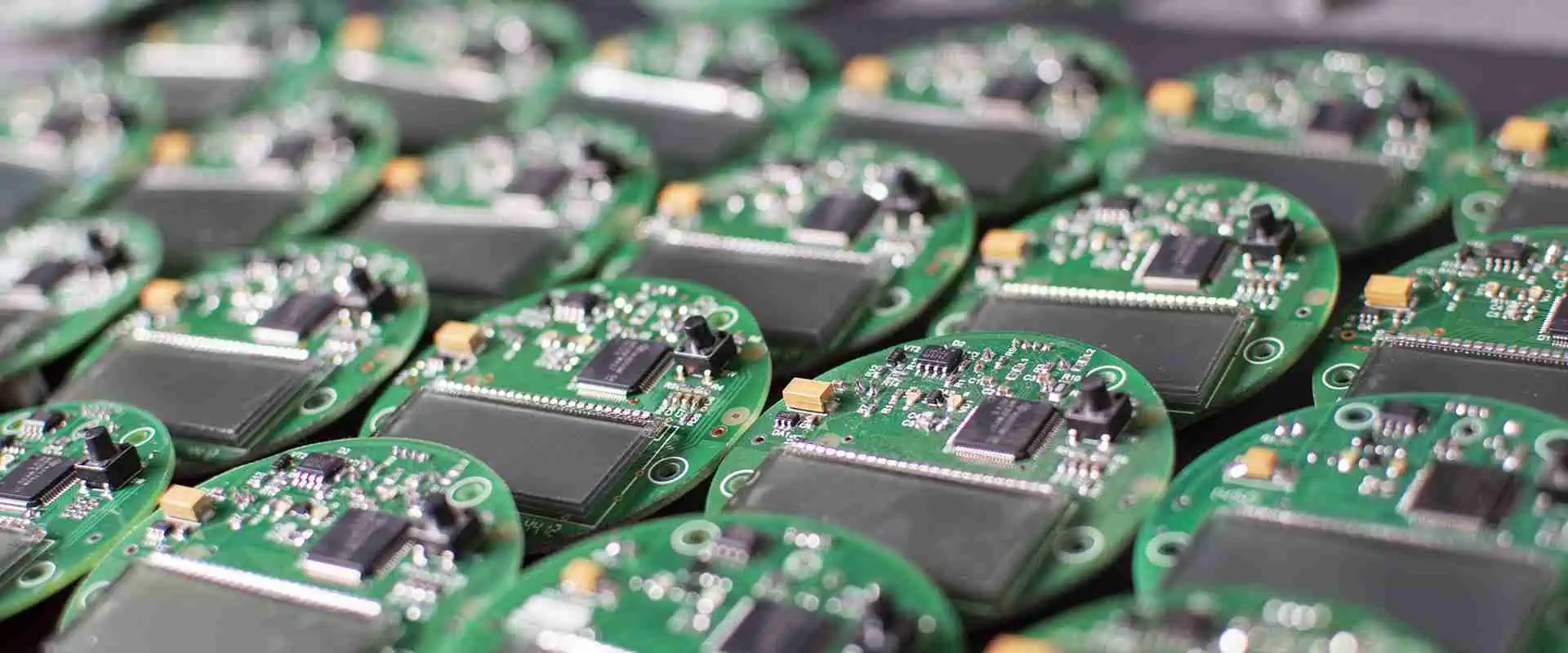
IPC-A-600 is a collection of visual quality acceptability requirements for PCBs. It sets the benchmark for PCB quality in the electronics industry, providing detailed criteria for evaluating the acceptability of bare printed boards. The standard covers various aspects of PCB manufacturing, from internal and external visual inspection to dimensional verification.

Evolution of IPC-A-600: From J to K

The IPC-A-600 standard has undergone several revisions to keep pace with advancements in PCB technology. The two most recent versions are:

  1. IPC-A-600J: Released in 2016
  2. IPC-A-600K: The latest version, released in 2020

Each new revision incorporates updates based on industry feedback and technological advancements, ensuring that the standard remains relevant and effective.

Key Areas Covered by IPC-A-600

The IPC-A-600 standard addresses various aspects of PCB quality, including:

  1. Board Edges
  2. Base Material
  3. Conductive Patterns
  4. Plated-Through Holes
  5. Solder Mask
  6. Marking
  7. Surface Finishes

Powered By EmbedPress

Importance of IPC-A-600 in the Electronics Industry

Ensuring Consistent Quality

The IPC-A-600 standard plays a crucial role in maintaining consistent quality across the PCB manufacturing industry. By providing clear, visual criteria for acceptability, it helps manufacturers, suppliers, and customers align their expectations and quality standards.

Facilitating Communication

A common language for PCB quality helps streamline communication between different stakeholders in the electronics supply chain. When everyone refers to the same standard, it becomes easier to discuss specifications, resolve disputes, and ensure that the final product meets the required quality levels.

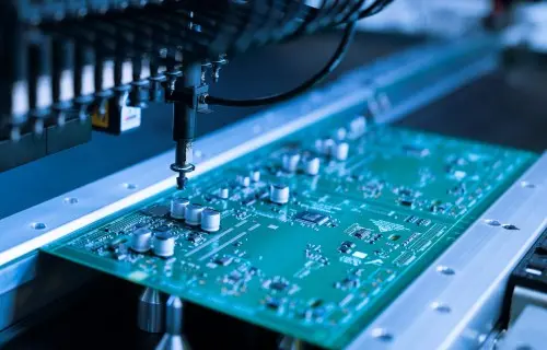
Improving Manufacturing Processes

By adhering to IPC-A-600, manufacturers can identify areas for improvement in their production processes. The standard serves as a benchmark against which companies can measure their output and implement continuous improvement initiatives.

IPC-A-600 Training and Certification

Overview of IPC Training Programs

The IPC offers comprehensive training programs for individuals and organizations looking to gain expertise in the IPC-A-600 standard. These programs are designed to equip participants with the knowledge and skills needed to effectively apply the standard in real-world scenarios.

Certified IPC Trainer (CIT) Program

The Certified IPC Trainer (CIT) program is designed for individuals who will be responsible for training others within their organization on the IPC-A-600 standard. CITs are authorized to conduct and certify Certified IPC Specialists (CIS) in their company.

Key aspects of the CIT program:

  1. Intensive training on the IPC-A-600 standard
  2. Instruction on effective teaching methods
  3. Hands-on practice with visual aids and inspection techniques
  4. Assessment of training skills and knowledge of the standard

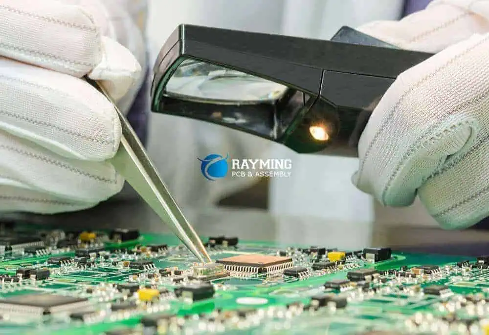
Certified IPC Specialist (CIS) Program

The Certified IPC Specialist (CIS) program is for individuals who will be directly involved in PCB inspection and quality assurance. CIS certification demonstrates proficiency in understanding and applying the IPC-A-600 standard.

Benefits of CIS certification:

  1. Enhanced knowledge of PCB quality criteria
  2. Improved ability to identify and categorize PCB defects
  3. Increased value to employers and customers
  4. Recognition as a skilled professional in the industry

Online vs. In-Person Training Options

IPC offers both online and in-person training options for IPC-A-600 certification:

  1. Online Training:ย Provides flexibility and convenience, allowing participants to learn at their own pace.
  2. In-Person Training:ย Offers hands-on experience and direct interaction with instructors and other participants.

Both options have their merits, and the choice depends on individual preferences and organizational needs.

Read more about:

Class 2 and Class 3 Requirements in IPC-A-600

Understanding PCB Classifications

The IPC-A-600 standard defines three classes of PCBs, each with different levels of acceptability criteria:

  1. Class 1:ย General Electronic Products
  2. Class 2:ย Dedicated Service Electronic Products
  3. Class 3:ย High-Reliability Electronic Products

Class 2 Requirements

Class 2 PCBs are designed for dedicated service electronic products where continued performance and extended life are required, and for which uninterrupted service is desired but not critical.

Key requirements for Class 2 PCBs:

  1. Moderate allowances for cosmetic imperfections
  2. Stricter tolerances compared to Class 1
  3. Focus on functionality and extended life

Class 3 Requirements

Class 3 PCBs are intended for high-reliability electronic products where continued performance or performance-on-demand is critical, equipment downtime cannot be tolerated, and the end-use environment may be uncommonly harsh.

Key requirements for Class 3 PCBs:

  1. Minimal allowances for cosmetic imperfections
  2. Tightest tolerances among all classes
  3. Emphasis on reliability and performance in demanding conditions

Comparing Class 2 and Class 3 Criteria

While both Class 2 and Class 3 have stringent requirements, Class 3 is generally more demanding in several areas:

  1. Conductor Width and Spacing:ย Class 3 has tighter tolerances for minimum conductor width and spacing.
  2. Plated-Through Hole Quality:ย Class 3 requires higher standards for hole wall plating and void allowances.
  3. Surface Finishes:ย Class 3 has stricter requirements for surface finish quality and coverage.
  4. Solder Mask:ย Class 3 allows fewer imperfections in solder mask application.

Key Changes in the Latest IPC-600K Version

Updates from IPC-600J to IPC-600K

The transition from IPC-600J to IPC-600K brought several important updates to the standard:

  1. Expanded Coverage:ย New sections added to address emerging technologies and manufacturing processes.
  2. Clarified Criteria:ย Refinement of existing criteria to reduce ambiguity and improve consistency in application.
  3. Updated Illustrations:ย Enhanced visual aids to better represent acceptable and unacceptable conditions.
  4. Alignment with Other Standards:ย Improved harmonization with related IPC standards for greater consistency across the industry.

Specific Improvements in IPC-600K

1. Enhanced Guidance on Flexible and Rigid-Flex PCBs

The latest version provides more comprehensive criteria for evaluating flexible and rigid-flex PCBs, reflecting their increasing use in modern electronics.

2. Updated Criteria for Microvia Technology

With the growing prevalence of microvia technology, IPC-600K offers more detailed guidance on acceptability criteria for these small, high-density interconnects.

3. Refined Surface Finish Requirements

The standard now includes updated requirements for various surface finishes, addressing advancements in finishing technologies and their impact on PCB reliability.

4. Improved Guidance on Laminate Integrity

IPC-600K provides clearer criteria for assessing laminate integrity, including updated guidelines for evaluating delamination and bubbles in PCB substrates.

Implementing IPC-A-600 in Your Organization

Steps for Adoption

  1. Assessment:ย Evaluate your current PCB quality standards and identify gaps compared to IPC-A-600.
  2. Training:ย Invest in IPC-A-600 training and certification for key personnel.
  3. Documentation:ย Update internal quality control documents to align with IPC-A-600 criteria.
  4. Equipment:ย Ensure you have the necessary inspection tools and equipment to apply the standard effectively.
  5. Process Integration:ย Incorporate IPC-A-600 criteria into your manufacturing and quality control processes.
  6. Supplier Alignment:ย Communicate your adherence to IPC-A-600 with suppliers and ensure they can meet the required standards.

Challenges and Solutions

Challenge 1: Resistance to Change

Solution: Educate staff on the benefits of adopting IPC-A-600, emphasizing improved quality and customer satisfaction.

Challenge 2: Initial Cost of Implementation

Solution: View the investment in training and equipment as a long-term strategy for reducing defects and improving product reliability.

Challenge 3: Interpretation of Criteria

Solution: Encourage open communication within your team and with IPC resources to clarify any ambiguities in the standard.

The Future of IPC-A-600

Emerging Trends

  1. Integration with Industry 4.0:ย Expect future versions of IPC-A-600 to address the integration of smart manufacturing and data-driven quality control.
  2. Sustainability Considerations:ย Future updates may incorporate guidelines for environmentally friendly PCB manufacturing practices.
  3. Additive Manufacturing:ย As additive techniques for PCB production evolve, the standard may expand to cover these new manufacturing methods.

Preparing for Future Revisions

To stay ahead of the curve:

  1. Actively participate in IPC standards committees
  2. Regularly review and provide feedback on draft revisions
  3. Stay informed about technological advancements in PCB manufacturing
  4. Maintain flexibility in your quality control processes to adapt to new requirements

Conclusion

The IPC-A-600 standard continues to be a cornerstone of quality assurance in the PCB industry. By understanding and implementing this standard, particularly the latest IPC-600K version, organizations can ensure they are producing high-quality, reliable printed circuit boards that meet the demanding requirements of modern electronics.

Whether you’re dealing with Class 2 dedicated service products or Class 3 high-reliability applications, the IPC-A-600 standard provides the guidance needed to achieve and maintain excellent PCB quality. Investing in proper training, certification, and implementation of this standard is crucial for staying competitive in the ever-evolving electronics manufacturing landscape.

As technology continues to advance, the IPC-A-600 standard will undoubtedly evolve to meet new challenges and opportunities. By staying engaged with the standard and its updates, PCB manufacturers and quality professionals can ensure they remain at the forefront of industry best practices, delivering superior products to their customers and contributing to the overall advancement of electronic technology.

All You Should Know About the IPC 4101 Slash Sheet?

PCB IPC standards

Before you do anything regarding planning your new circuit board layout, one thing you will have to do is designing the stackup as well as selecting your boardโ€™s material system. The circuit board laminate materials may seem simple. You believe it works like choosing your desired material and vendor, putting them in your stackup, then sending it to the fabricator.

The truth is that not every fabricator out there stock or support all the laminate materials possible. However there are some materials, which are compatible with themselves in the different stackups. Now, in what ways can you spot the resin system and materials that will be interchanged in the PCB stackup?

Enter the IPC standard IPC-4101 slash sheets. This standard helps in specifying the different requirements for the materials of the PCB laminate which helps in ensuring the compatibility and interchangeability in the PCB stackup. Though it is not required to read any slash sheets during the selection of materials, having understanding of whatโ€™s present in the slash sheet may assist you in determining the alternate materials when the desired laminates are not supported or available by the manufacturer.

Powered By EmbedPress

The Origin of the IPC 4101 Slash Sheet

Under IPC standards, the IPC 4101 slash sheets can be described as addenda which stats the requirements for the different laminates for the PCB stackups. The IPC 4101 standard utilized most of the initial languages from the MIL-S-13949 standard.

The slash sheets requirements for IPC 4101 persist till today and the laminate materials would list these slash sheets onto which the materials conform. If you check the website of a laminate manufacturer, or you check the datasheets of their laminate, you will most likely see something like โ€œ/24โ€ orโ€/121โ€ for some specific laminates. This refers to the IPC 4101 24 or IPC 4101/121 slash sheets respectively. Others include IPC 4101 126, IPC 4101 21, IPC 4101 26, and IPC 4101 41.

What Can You Find in a Slash Sheet?

IPC-for-pcb

The slash sheet features two data sets on a specific material system. These are the material/primary structural properties, as well as some results for testing as determined using the IRC testing standard. In addition, any slash sheet begins with structural and material specifications for that specific laminate.

All manufacturers have their material names which aid in communicating the specific laminates onto the public and the customers. However, there will be a relationship between the laminates and the IPC 4101 standard. Below are some of the information you will find in slash sheets.

  • Type of reinforcement which is usually fiberglass
  • All flame retardants and filler materials available in the laminates
  • Tg or glass transition temperature
  • Resin material systems (which is usually an epoxy mix)

What is IPC 4101?

IPC 401 can be described as a specification for the base materials designed for multilayer and rigid printed circuit boards. It was released in December 1997. This came as a replacement for the MIL-S-13949 standard. Moreover, it had most of the same wording seen in the military standard.

Furthermore, its format appendix was maintained to a standard specifying the fiber and resin system of several PCB laminates, in addition to the properties and testing parameters. At first, 41 (forty-one) slash sheets were available; however, as the industry decided to work with โ€œGreenโ€ and โ€œLead Freeโ€ processes, these slash sheets increased in number to sixty six (66).

With all these slash sheets, having a good understanding of what they are would offer great benefits to the choosing of the right properties of the laminate to suit your PCB design.

Laminate Specification of IPC 4101

All slash sheets start with a laminate specification. It involves the type of reinforcement, the resin system, the mechanism of the flame retardant, glass transition, and fillers. This type of reinforcement seems to be fiberglass (woven E-glass).

However, it could also be exotic fiberglass and cellulose paper types like aramid and unidirectional fiber. This serves as the laminateโ€™s structure component. Also, resin systems could be a combination of different types of epoxies to meet the laminate typeโ€™s requirements. The main epoxy would be listed, after this, the secondary follows, and another secondary may even follow.

Utilizing Epoxy Resins

 Some exotic resin systems like Polyphenylene and polyimide exist. This resin system binds the layers of the structure together. This flame retardant is usually RoHS compliant bromine or bromine, and phosphorus as another option as well. Fillers could be inorganic or not applicable, with just a few types of laminate making use of kaolin fillers. These fillers help in reducing resin shrinkage, therefore, reducing the formation of cracks in the filled areas.

Temperature of Glass Transition (Tg)

The temperature of glass transition describes the range of temperature whereby the resinโ€™s molecules transits from its brittle and rigid state into its pliable and flexible state. The Tg was added to the area of specification because many designers decided to base their choice of laminate for compliance of RoHS on the Tg material. Asides from Several other factors which have to be considered during the selection of laminates.

Other Characteristics That You Must Be Aware of

The remaining slash sheet must list the requirements of the laminate for the material characteristics, which are tested for every IPC-TM-650 test method. Some of these features are highlighted below.

  • The peel strength helps in determining the metal cladding bond whenever it is tested after thermal stress, as well as after exposure to some processing chemicals
  • Absorption of moisture or moisture absorption helps in determining the absorption rate for that epoxy composite utilized in the structure of the laminate. Also, all the resin systems help in absorbing some moisture whenever it is exposed to a high humidity environment.
  • Surface and volume resistivity determines the surface and cross-sectional electrical resistance of a dielectric material when under some humid conditions.
  • Dielectric breakdown measures the ability of the insulator to withstand the high voltages stress that is placed across.
  • Loss Tangent can be described as a measure of the amount of electromagnetic field that travels through the dielectric is lost or absorbed in the dielectric
  • Also, you can determine flexural strength with laminates having a thickness of 0.51 mm or greater through the application of a load to a size as well as shaped specimen.
  • Thermal stress helps in determining the metallic clad or unclad laminatesโ€™ thermal integrity making use of short-term solder exposure.
  • Arc resistance measures the required time to make the insulating surface to be conductive when under low current and high voltage arc.

IPC 4101 vs IPC 4103: Whatโ€™s the Difference?

FULL PCB MANUFACTURING Quote

When searching for slash sheets from your laminate manufacturer, you may see both IPC 4101 and IPC 4103 standards. This IPC 4101 standard deals with the standard laminates as well as prepreg materials, thereby encompassing the materials of epoxy resin with fiberglass.

Though the standard initially specified a total of forty-one slash sheets, this number has increased to over sixty slash sheets. This is made possible by RoHS regulations as well as focus on the lead-free environmentally-friendly materials. This IPC-4102 also extends the slash sheets to the copper-unclad as and clad plastic laminate materials as well as bondply materials utilized in high frequency and high speed PCBs.

Calculate and Plan Your Stackup Early

Most, if not everyone, have a manufacturer that they prefer to use. With time, when you continue to order from one manufacturer, you will be very familiar with the materials as well as the stackups that they support.

Normally, this is listed by the laminate vendor number and name, instead of making use of slash sheet numbers. Moreover, there are fab houses that need you to specify the stackup you desire through a slash sheet. T5his is why it is important that this information is gotten from your own laminate manufacturer whenever you are submitting an order.

Preferred Circuit Board Stackups

Majority of manufacturers have stackups that they prefer, which are utilized for some layer counts and they are sure of passing through their process of fabrication. These stackups they prefer will feature some specific material systems. Make sure you work closely with the fabricator ensuring that your ideal stackup will be supported throughout the entire process

Where You Can Find Stackup Data

There are several fabrication houses that will place this online, while others will decide to email it to you. Whatever the case is, try to ask early. Failure to do this could lead to a very complex redesign when the stackup needs to be modified in the completed PCB layout, most especially whenever you are working with an impedance controlled board.

Furthermore, ensure you check your data sheets from the two materials to ensure their compatibility. You may even go ahead and order test samples, just to check the Thermomechanical and impedance properties.

Conclusion

In summary, IPC 4101 can be described as an industry guideline for the printed circuit boardsโ€™ base laminates. Having a good understanding regarding the structure and content will lead the designers to select the laminate which best offers support to the final requirements of the product.

Comprehensive Guide to IPC Standards for PCB Assembly: Ensuring Quality & Reliability in Electronics Manufacturing

through-hole assembly process

In the ever-evolving world of electronics manufacturing, maintaining consistent quality and reliability is paramount. At the heart of this pursuit lies a set of industry-wide standards known as IPC Standards for PCB Assembly. These standards, developed by the Association Connecting Electronics Industries (formerly known as the Institute for Printed Circuits), serve as the backbone for ensuring excellence in printed circuit board (PCB) design, manufacturing, and assembly processes.

This comprehensive guide will delve deep into the world of IPC Standards for PCB Assembly, exploring their significance, key components, and impact on the electronics manufacturing industry. Whether you’re a seasoned professional or new to the field, this article will provide valuable insights into the standards that shape the quality and reliability of electronic devices we use every day.

Powered By EmbedPress

Understanding IPC Standards for PCB Assembly

What Are IPC Standards?

IPC Standards are a set of guidelines and specifications developed by the IPC (Association Connecting Electronics Industries) to ensure consistency, quality, and reliability in the electronics manufacturing industry. These standards cover various aspects of PCB design, fabrication, and assembly, providing a common language and benchmarks for manufacturers, suppliers, and customers worldwide.

The Importance of IPC Standards in PCB Assembly

IPC Standards for PCB Assembly play a crucial role in maintaining quality and reliability in electronics manufacturing. Here are some key reasons why these standards are essential:

  1. Quality Assurance: By adhering to IPC Standards, manufacturers can ensure that their PCB assemblies meet industry-recognized quality benchmarks.
  2. Consistency: Standards provide a uniform approach to PCB assembly, reducing variations and inconsistencies across different manufacturers and production runs.
  3. Cost Reduction: Implementing standardized processes can lead to improved efficiency and reduced waste, ultimately lowering production costs.
  4. Customer Confidence: Products manufactured in compliance with IPC Standards instill greater confidence in customers, as they are assured of the quality and reliability of the end product.
  5. Global Compatibility: IPC Standards are recognized worldwide, facilitating international trade and collaboration in the electronics industry.

Read more about:

Key IPC Standards for PCB Assembly

IPC-A-610: Acceptability of Electronic Assemblies

IPC-A-610 is one of the most widely used standards in the electronics industry. It provides visual acceptance criteria for electronic assemblies and is often referred to as the “bible” of the industry.

Key Features of IPC-A-610:

  1. Three Classes of Products: The standard defines three classes of electronic products based on reliability requirements:
    • Class 1: General Electronic Products
    • Class 2: Dedicated Service Electronic Products
    • Class 3: High-Performance/Harsh Environment Electronic Products
  2. Visual Inspection Criteria: It provides detailed guidelines for visual inspection of various aspects of PCB assembly, including component placement, soldering, and overall board quality.
  3. Defect Classification: The standard classifies defects into three categories:
    • Accept: Meets the minimum requirements
    • Process Indicator: May require process improvement but is acceptable
    • Defect: Requires rework or repair
  4. Illustrated Examples: The standard includes numerous photographs and illustrations to help inspectors identify and classify defects accurately.

IPC-J-STD-001: Requirements for Soldered Electrical and Electronic Assemblies

IPC-J-STD-001 is a companion standard to IPC-A-610, focusing specifically on the materials and processes used in producing soldered electrical and electronic assemblies.

Key Aspects of IPC-J-STD-001:

  1. Material Requirements: It specifies the requirements for materials used in soldering, including solder alloys, fluxes, and cleaning agents.
  2. Process Control: The standard outlines procedures for controlling various aspects of the soldering process, such as temperature profiles and cleanliness.
  3. Acceptance Criteria: It provides detailed acceptance criteria for soldered connections, including through-hole and surface mount technology (SMT) assemblies.
  4. Specialized Requirements: The standard includes specific requirements for unique assembly types, such as wire and terminal connections.

IPC-7711/7721: Rework, Modification and Repair of Electronic Assemblies

This pair of standards provides guidelines for reworking, modifying, and repairing electronic assemblies. They are essential for maintaining the quality and reliability of PCBs throughout their lifecycle.

Key Features of IPC-7711/7721:

  1. Rework Procedures: The standards outline step-by-step procedures for various rework operations, such as component removal and replacement.
  2. Modification Guidelines: They provide guidance on how to modify existing PCB assemblies without compromising their integrity.
  3. Repair Techniques: The standards describe techniques for repairing damaged PCBs and components, ensuring that repaired assemblies meet the same quality standards as new ones.
  4. Tools and Equipment: They specify the appropriate tools and equipment to be used for rework, modification, and repair operations.

Implementing IPC Standards in PCB Assembly

Training and Certification

To effectively implement IPC Standards for PCB Assembly, it’s crucial to have a well-trained workforce. The IPC offers various training and certification programs to ensure that personnel involved in PCB assembly are knowledgeable about the standards and their application.

Key Training Programs:

  1. IPC-A-610 Certified IPC Specialist (CIS): This program trains individuals in the visual acceptance criteria for electronic assemblies.
  2. IPC J-STD-001 Certified IPC Specialist: This certification focuses on soldering processes and acceptance criteria.
  3. IPC-7711/7721 Certified IPC Specialist: This program trains technicians in rework, modification, and repair techniques for PCB assemblies.

Establishing Quality Control Processes

Implementing IPC Standards requires robust quality control processes throughout the PCB assembly workflow. Here are some key steps to establish effective quality control:

  1. Incoming Inspection: Implement thorough inspection procedures for incoming materials and components to ensure they meet IPC Standards before entering the assembly process.
  2. In-Process Quality Checks: Conduct regular quality checks at various stages of the assembly process to catch and correct issues early.
  3. Final Inspection: Perform comprehensive final inspections of assembled PCBs using IPC-A-610 criteria to ensure the final product meets all quality requirements.
  4. Documentation and Traceability: Maintain detailed records of all quality control activities, including inspection results, rework operations, and any deviations from standards.

Continuous Improvement

Adhering to IPC Standards for PCB Assembly is not a one-time effort but a continuous process of improvement. Here are some strategies for ongoing enhancement:

  1. Regular Audits: Conduct internal audits to assess compliance with IPC Standards and identify areas for improvement.
  2. Data Analysis: Analyze quality control data to identify trends and recurring issues, allowing for targeted process improvements.
  3. Staff Training: Provide ongoing training to keep staff up-to-date with the latest revisions to IPC Standards and best practices in PCB assembly.
  4. Supplier Management: Work closely with suppliers to ensure they adhere to IPC Standards, maintaining quality throughout the supply chain.

Advanced Topics in IPC Standards for PCB Assembly

IPC-6012: Qualification and Performance Specification for Rigid Printed Boards

While not directly related to assembly, IPC-6012 is crucial for ensuring the quality of the PCBs used in assembly processes. This standard sets the requirements for qualification and performance of rigid printed boards.

Key Aspects of IPC-6012:

  1. Performance Classes: Similar to IPC-A-610, it defines three classes of PCBs based on reliability requirements.
  2. Qualification Requirements: It outlines the tests and inspections required to qualify a PCB for use in electronic assemblies.
  3. Electrical Properties: The standard specifies requirements for electrical properties such as impedance control and dielectric withstanding voltage.
  4. Physical Properties: It defines requirements for physical properties like dimensional stability and thermal stress resistance.

IPC-2221 and IPC-2222: Generic Standard on Printed Board Design

These standards provide guidelines for PCB design, which directly impacts the assembly process. Understanding these standards can help assembly professionals work more effectively with design teams.

Key Features of IPC-2221 and IPC-2222:

  1. Design Considerations: They cover various aspects of PCB design, including layer stackup, conductor spacing, and pad design.
  2. Design for Manufacturability (DFM): The standards provide guidance on designing PCBs that are easier to manufacture and assemble.
  3. Thermal Management: They include guidelines for designing PCBs with effective thermal management, crucial for high-power applications.
  4. Signal Integrity: The standards address design considerations for maintaining signal integrity in high-speed circuits.

IPC-4101: Specification for Base Materials for Rigid and Multilayer Printed Boards

This standard is essential for understanding the properties of the base materials used in PCB manufacturing, which can impact assembly processes and final product reliability.

Key Aspects of IPC-4101:

  1. Material Classifications: It defines various types of base materials and their properties.
  2. Performance Requirements: The standard specifies performance requirements for different material types, including electrical, mechanical, and thermal properties.
  3. Testing Methods: It outlines standardized testing methods for evaluating base material properties.
  4. Environmental Considerations: The standard addresses environmental factors, such as flammability ratings and halogen content.

The Future of IPC Standards for PCB Assembly

High Volume Assembly Line

As technology continues to evolve, IPC Standards for PCB Assembly must adapt to new challenges and innovations in the electronics industry. Here are some trends and developments to watch:

Miniaturization and High-Density Interconnect (HDI)

As electronic devices become smaller and more complex, PCB assemblies are moving towards higher density and finer pitch components. IPC Standards will need to evolve to address the challenges associated with assembling and inspecting these highly miniaturized boards.

Flexible and Rigid-Flex PCBs

The increasing use of flexible and rigid-flex PCBs in various applications, from wearable devices to aerospace, will require updates to existing standards and potentially new standards specifically addressing these technologies.

Advanced Materials

The development of new PCB materials, such as those designed for high-frequency applications or extreme environments, will necessitate updates to standards related to material specifications and assembly processes.

Industry 4.0 and Smart Manufacturing

As the electronics manufacturing industry embraces Industry 4.0 concepts, IPC Standards may need to incorporate guidelines for integrating smart manufacturing technologies, such as real-time process monitoring and data analytics, into PCB assembly processes.

Sustainability and Environmental Considerations

With growing emphasis on sustainability, future revisions of IPC Standards may include more comprehensive guidelines for environmentally friendly manufacturing processes, material selection, and end-of-life considerations for electronic assemblies.

Conclusion: The Enduring Importance of IPC Standards for PCB Assembly

In conclusion, IPC Standards for PCB Assembly play a vital role in ensuring the quality, reliability, and consistency of electronic products in an increasingly complex and demanding industry. From providing clear acceptance criteria for assembled PCBs to guiding the entire manufacturing process, these standards serve as the foundation for excellence in electronics manufacturing.

As we’ve explored in this comprehensive guide, adhering to IPC Standards offers numerous benefits, including improved quality assurance, cost reduction, and enhanced customer confidence. By implementing these standards through proper training, robust quality control processes, and a commitment to continuous improvement, manufacturers can position themselves at the forefront of the electronics industry.

Looking to the future, IPC Standards will continue to evolve, addressing new technologies, materials, and manufacturing processes. Staying informed about these developments and actively participating in the standards development process will be crucial for companies wanting to maintain a competitive edge in the global electronics market.

Whether you’re a PCB assembly professional, a quality control specialist, or an electronics engineer, understanding and implementing IPC Standards is essential for success in today’s high-tech manufacturing landscape. By embracing these standards and the principles they represent, we can collectively drive innovation, quality, and reliability in the electronics that shape our world.

How the IPC 2221A Standard Impact PCB Insulation Design

PCB IPC standards

When it comes to PCB manufacturing, assembly, and design, there are certain standards to follow. It is crucial that industries and organization set specific standards for their activities. Standards are what help us to achieve success in whatever field we find ourselves. Regardless of the industry you are, it is of utmost importance to adhere to the standards set out in that industry.

Furthermore, it is important to opt for an electronic contract manufacturer that adheres to IPC standards for PCB assembly and design. There are several standards in the PCB and electronics industry. However, the IPC standard stands out. Also, this standard covers every process in PCB manufacturing. The functionality and reliability of your PCB design depend on the ability of your electronic contract manufacturer to work with IPC standards.

YouTube video

Also, the IPC standard is a recognized and acceptable standards in the electronic and PCB manufacturing industry. It is often referred to as the basis on which PCB design recommendations are established. There are several IPC standards. However, our major focus in this article is the IPC 2221A standard.

What are IPC standards?

IPC-for-pcb

IPC is an abbreviation that refers to the Institute for Printed Circuits. It is an official name for the association that designs PCB-related standards. In addition, the IPC standard is an acceptable and recognized standard for PCB design, electronic assembly, and PCB manufacturing. In 1998, the official name for the IPC changed to Association Connecting Electronics Industries. However, it is still commonly called IPC to date.

Also, the IPC standards create the basis for assembly, design, packaging, and inspection requirements for the electronics industry. IPC standards set out standard that serve as a guideline for PCB fabrication, design, test, and assembly. Also, these standards can determine the failure or success of a product if PCB designers comply with them.

There are several factors in PCB design that can impact the manufacturability and reliability of a circuit board. For instance, PCB designers can guess the perfect side of pad for THT components. Therefore, designing without compliance with the IPC standards might result in non-conformance of uniformity between manufacturers and designers.

There are different IPC standards for PCB design layout. These include IPC 2221, IPC 221A, IPC 2222, and IPC 2223. The IPC standards are the most widely acceptable standards in the electronics industry. Also, IPC establishes standards for the electronics industry. Therefore, it plays a significant role in PCB manufacturing. Furthermore, IPC standards are crucial for every stage of PCB manufacturing.

What is the IPC 2221A Standard?

Our major focus is the IPC 2221A standard. The IPC 2221A standard creates generic requirements for Organic PCB design and other forms of interconnecting structures. Also, the organic materials may be integrated or reinforced with inorganic materials. IPC 2221A is a guideline for the process of PCB design. This standard addresses topics like design layout, materials, and parts lists.

Also, it is a reference document that has been revised on several occasions. The specific standards stated in this document helps to determine all aspects of PCB design. Also, this document offers the structure for interconnecting electromechanical, mechanical, and electronic components.

Furthermore, the IPC 2221A a crucial standard that covers almost every aspect of PCB design. This standard creates the generic requirements for PCB designs. Selecting materials for a PCB and designing its physical features requires balancing the mechanical, thermal, and electrical performance. Also, it requires balancing the cost, manufacturing and cost of a circuit board.

What Issues Does the IPC 2221A Standard Address?

FULL PCB MANUFACTURING Quote

The IPC 2221A covers a large area of PCB design. Also, it talks about the most important considerations for PCB design.

Design layout

According to the IPC 2221A standard, the layout process should include a design review of layout information. The layout approval will ensure that the manufacturing-related factors were fully considered in the design. Also, there are several interrelated considerations that determine performance of an interconnecting structure design.

As regards end-product usage, it crucial to consider the impact of the following parameters on the design:

  • Installation interface that impact the location and size of connector, mounting holes, and the placement of parts and brackets.
  • Equipment environmental conditions like heat produced by the components, shock, and vibration, ambient temperature, and ventilation.
  • Manufacturing limitations like minimum plating thickness, board shape, minimum etched features, etc.
  • Type of assembly technology used; through hole, surface mount, and mixed.

Parts list

A parts list in a PCB design refers to the tabulation of materials and parts utilized in the construction of PCBA. Also, the list will include all end item identifiable materials and parts. The materials excluded are those used in the manufacturing process. However, many include specifications pertinent to the assembly manufacturer and reference to the logic diagram.

Electronic components like resistors, transistors, fuses, etc will have reference designators. Electrical reference designators assignment shall be similar to the assignments given to similar components on the logic diagram. Group similar items like capacitors, resistors, and ICs in numerical or ascending order.

Test requirement considerations

Before starting a PCB design, there should be a testability review meeting with fabrication and testing. Also, testability concerns like circuit controllability, circuit visibility, and test requirements should be discussed as an aspect of a test strategy.

Material Selection for IPC 2221A Standard

There is a wide range of materials a PCB designer can select from. Also, these materials range from standard to specialized, and highly sophisticated. Therefore, during material specifications, the designer needs to determine the requirements of the PCB application. This means that the PCB designer must understand the requirements the circuit board must meet.

Furthermore, these requirements include interconnections, circuit density, electrical properties, etc. Also, highly sophisticated materials will require increased processing and material costs. When designing a composite from materials having varying temperature characteristics, the greatest end-use temperature allowed must be restricted to the lowest rated material.

Other requirements like thermal stability, resin formula, and flame resistance may be crucial when comparing various materials.

Properties to consider when choosing materials for PCB

Structural strength

When selecting laminate, you need to define the service requirements the material must need. Service requirements like shock, vibration, and environment.  The laminate choice should comprise standard materials to prevent time consuming and costly tasks. Also, the choice of laminates should maintain the best balance of properties.

Materials should be available in the size and form required. Special materials can be costly and have longer lead times.

Environmental properties

The environmental properties of common dielectric materials included glass transition temperature, flexural modulus, and tensile strength.

Electrical properties

Some crucial properties to look out for include moisture resistance, electrical strength, hydrolytic stability, and dielectric constant. You can consult the manufacturer of the laminate for specific values.

Materials Recommended by IPC 2221A Standards

Epoxies

Epoxy resin is known as a versatile adhesive for mechanical and insulating bonding applications. This material provides various electrical and physical properties like chemical resistance, thermal vacuum stability, and cohesive strengths. Also, epoxy resin comes with several cure methods and time. furthermore, epoxies are available with various fillers, reinforcements, and modifiers.

Conductive materials

Metallic coatings determine the creation of conductive pattern. This specific plating provides additional benefits like long term solderability, corrosion prevention, and wear resistance.  The IPC standards provide integrity and thickness requirements for metallic coatings and platings.

Organic protective coatings

According to IPC 2221A standard, markings and coating must be compatible with each other and other parts in the PCB and PCBA. The utilization of solder resist coatings must be according to the requirements of the IPC. The dielectric properties of solder resist can maintain electrical integrity when solder resist function as an electrical insulator.

Semiconductive coatings

Semi Conductive coatings function as a conductive starter coating before electrolytic copper plating. These coatings are usually applied to the hole. Therefore, the coating should be of good quality to ensure subsequent metallic deposition. Tin and palladium are materials commonly used for these coatings. Also, the PCB manufacturer deposits a thin layer on exposed surfaces, particularly the drilled holes. Therefore, this offers a surface to auto-catalyze the deposition of electroless copper.

Considerations for Power Distribution in PCB Design

A crucial factor that requires great consideration in PCB design is power distribution. Also, the grounding scheme can serve as part of the distribution system. The grounding scheme offer both DC power return and AC reference plane. Consider the following for power distribution in PCB design:

  • Use enough decoupling capacitance to decouple the power distribution at the PCB connector. Also, distribute enough power/ground decoupling capacitors throughout the areas of the logic device board.
  • Ensure you maintain a low RF impedance throughout the distribution of the DC power. Also, a ground that is not properly designed can lead to RF emissions.
  • Keep capacitor leads very short and place them adjacent to the crucial circuit to reduce the radiation and impedance loop of the coupling capacitor.
  • Use planes for ground and power distribution. This is a good way to distribute grounds and power in a multilayer PCB is to integrate planes. It is advisable to make the ground signals and incoming power to terminate before connecting to the internal planes.
  • Run power traces very close to ground planes when utilizing power conductors. Both ground and power traces should be wide enough. The ground and power planes should would become one plane.
  • Design the power and grounding first in digital power distribution schemes. Also, route all interfacing to a single reference edge. Avoid opposing end interconnections. If you canโ€™t avoid them, be careful when routing ground and power away from active PCBs.
  • All ground structures should be heavy enough at the interconnection reference edge.
  • Use the shortest conductor length between devices. Also, PCBs should be in separate areas for low, medium, and high frequency circuits.

IPC 2221A Guidelines for Designing PCB Assemblies

Consider the following guidelines when designing circuit board assemblies

  • Identify the correct polarity of the component when possible
  • Ensure you identify transistor base and collector properly
  • Keep grounding planes or buses apart from each other when using different grounds
  • Analog design should consider signal conductors and ground conductor connections last
  • Ensure heat-radiating and heat-sensitive are kept as farย away as possible. Also, you can integrate heatsinks when necessary.

Benefits of Complying With IPC 2221A Standards in PCB Design

IPC 2221A standards play a crucial role in printed circuit board design. Manufacturing reliable and functional PCB products requires careful attention to detail. Also, commitment to quality is necessary throughout the manufacturing process.

With several standards for PCB design and assembly, you can integrate the IPC 2221A standard for almost all stages of production. PCB companies must adhere to the IPC standards to achieve high-quality PCBs that meet the requirements of customers. Below are the benefits of complying with the IPC 2221A standard.

Improved PCB design quality

The IPC 2221A standard creates generic requirements for Organic PCB design and other forms of interconnecting structures. When these standards are severely adhered to, a PCB designer will achieve high quality PCB design. Also, the guidelines of this standard focus on creating quality and reliable PCB. Therefore, it addresses possible issues PCB designers may encounter during PCB design. This helps PCB designers to plan for potential issues during the design phase.

Reduced costs

One of the benefits of IPC 2221A standards is that it helps to reduce costs. Reducing miscommunication and increasing quality minimizes the possibilities of reworks and delays. Also, IPC standards enable companies to reduce resource use and improve efficiency.

Ensures smooth workflow during PCB manufacturing and assembly

The IPC 2221A standard helps to ensure a smooth workflow during PCB assembly and manufacturing. Also, the PCB manufacturing process involves several stages. With the right information and procedure, the PCB manufacturer can work through these stages without difficulty.

Conclusion

IPC 2221A creates standards for PCB design. As the technology world experiences advancements, specific standards require update. Therefore, the IPC 2221A standard has some new focus standards and updates. We have discussed the impact of IPC 2221A standard in PCB design. There is no doubt that this standard has a positive impact not only on PCB design, but also PCB manufacturing and assembly.

The difference between Class 2 and Class 3 in the PCB IPC standards

PCB IPC standards

The abbreviation IPC stands for International Patent Classification. It was established in 1971 under the Strasbourg Agreement. The PCB IPC standard uses language-independent symbols to provide a hierarchical system. Today, the majority of the high-tech companies in the industry are using IPC electronics. For one to effectively understand and use the IPC standards, they have to learn the different classes. We will look at the meaning, categorization, and significance of complying with IPC standards.

YouTube video

Definition of IPC Class

One must adhere to PCB when manufacturing electronics. Further, there are three fundamental categories that PCB electronics fall to. These categories define and show the different circuit board quality levels. They are class 1, class 2, and class 3. Class 1 is the lowest quality level, while class 3 is the highest quality level. All these classifications fall under the IPS-6011 standards. So we can define an IPC class as the PCB categorization standard used in electronics.

Class definition and significance of classification

Various manufacturers apply these classifications to PCB products for different reasons. Some of the existing codes and the three classifications ensure adherence to the allowed number of defects and severity in a PCB product.  

The lowest PCB quality level, class 1, has a significant acceptance rate of defective aspects. However, Class 3 PCB products have a very low tolerance to manufacturing defects. Circuit boards with multiple defects will not make it to the class 3 level. The stringent restriction on class 3 PCB products drives manufacturers to go above and beyond to ensure that their products meet the class 3 quality level if they want to remain relevant.

Defining the IPC categories

IPC for pcb

Here, we will define the IPC classes concerning their significant elements to help buyers choose a suitable product.

Class 1 โ€“ General Electronic Products

We can categorize class 1 products under the electronic boardsโ€™ group. These products have simple functions and a short lifespan. They comprise the day-to-day electronic product that we have at home and are easy to find. They include products such as TV remote control, LED lights, and childrenโ€™s toys. Most of the productsโ€™ lifespan is relative to their cost.

Class 2 โ€“ Dedicated Service Electronic products

This Class exhibits higher characteristics compared to class 1 boards. Class 2 boards have an extended lifespan and are more reliable. To achieve this long lifespan and reliability, the products go through stringent standards in their manufacturing. Class 2 boards are not highly critical, and they run continuously. We find class 2 boards on devices such as tablets, communication equipment, laptops, and smartphones.

Class 3 โ€“ High-reliability Electronic Products

These are highly critical products that must continuously provide the required performance at all times. Equipment with class 3 boards should not experience any downtime. During the manufacturing process, the class 3 products undergo a high level of inspection to ensure that they are reliable and dependable. Equipment that uses class 3 boards includes electronic manufacturing systems, support systems, and military devices.

A-Level or IPC 6012 class 3 โ€“ Advanced Electronic Products

The IPC 6012 class 3 is the topmost level and goes through highly stringent manufacturing processes. The PCB products in this class include aerospace applications, military airborne systems, missile systems, space equipment, and military avionics. Similar to their high standards and regulation in manufacturing, their design and production cost is very high.

Advantages of Class 2 PCB manufacturing

Most of the devices we used daily belong to Class 2 PCB. The popularity of class 2 boards are because of the following advantages:

  • Inspection

It is easier to perform an inspection on class 2 boars compared to class 3 ones. For example, the specific rules guiding class 3 components increase the inspection time. And the more time it takes, the high the cost rises. On the other hand, class 2 boards have an easy and fast inspection process which takes less time.

  • Manufacturing

It takes a lot of time when manufacturing class 3 boards since some processes need to slow down to achieve perfection. In manufacturing, the more time one takes on the product, the more the expenses grow, making the products very expensive. A close examination of the manufacturing process shows that one uses 75% of the solder to fill thru-hole leads when working with class 3 IPC standards. However, with class 2 boards, one uses only 50% solder.

  • Design

One must exercise low tolerance to defects and follow stringent specifications when manufacturing class 3 boards. But for class 2 PCBs, the rules are not as rigorous, and they have a simple design. With class 2 products, you can easily place and route all the components.

Advantages of Class 3 Production

IPC 6012 class 2

Class 3 products are fundamental in keeping planes noticeable all around, people alive, and organizations to remain set up. Class 3 boards have unquestionable requirements when dependability and broadened lifetime of an item are fundamental. Below is a portion of the benefits that accompany type 3 PCB production.

  • Inspection

With regards to examination matters, you will notice that Class 3 goes through a thorough assessment. While others may contend that this is costly, makers will keep away from costs related to bad reviews because of defective items over the long haul. A careful assessment guarantees the distinguishing proof of deficiencies right on time before full creation. With such, the organization will acquire the trust of its clients dependent on high-performing hardware.

  • Manufacturing

There is a world of difference between class 2 and class 3 manufacturing processes. Class 3 products go through a greater manufacturing detail compared to class 2 boards. While this manufacturing process might be moderate, eventually, it achieves excellent boards comprising of well-adjusted parts.

  • Design

For a product to meet class 3 standards, they go through their process under close determinations. Consequently, clients of this hardware appreciate the affirmation of superior grade and dependable items. Their plan is exact, cautious, and up to the necessary industry specification.

Difference between Class 2 and Class 3 Assembly

As referenced in the definition, Class 2 items are of a somewhat lower quality contrasted with Class 3 items. As such, the higher the quantity of the Class, the better its degree of value. So, what is the distinction between the assembly of Class 3 and Class 2 boards? The significant differences include:

  1. The distinction in the barrel fill levels

A significant separating factor between Class 2 and Class 3 boards respects the total barrel fill that manufacturers use in the thru-hole leads. Class 2 items devour less barrel fill (half) than the three quarters utilized by Class 3 items. It is a fragile procedure getting the necessary measure of glue to little plated through-hole.

  • Refined assembly

Class 3 boards are much dependable and have an extremely long life expectancy. They are additionally ideal for high-unwavering quality electronic gadgets. Therefore, it implies that their assembly cycle is reasonably refined contrasted with Class 2.

  • Installation and cleanliness

A critical distinction between the two classes is the quality and thoroughness they will go through. The installation and cleanliness of parts among them are extraordinary.

Since clinical and military applications predominantly use class 3 products, they need intensive cleaning. Additionally, the cautious installation of its parts is not optional when contrasted with Class 2.

These items need a detailed and cautious assembly measure. They are answerable for keeping planes flying and those in intensive care. The Assembly cycle must be thorough, not normal for IPC Class 2 items. For Class 3 items, there are no missteps or defects during the assembly cycle.

Difference between class 2 and class 3 PCB production

  • PCB through-hole plating prerequisites

Class 3 items will, in general, be marginally astringent, particularly for copper voids. They are circumstances where copper plating in the openingโ€™s barrel is not present. It will, in general, leave the penetrated holesโ€™ dielectric material uncovered. Then again, IPC Class 2 allows a stipend of five percent critical opportunity of a solitary void in the boardโ€™s holes. With regards to plating thickness prerequisites, Class 3 requires one mil while Class 2 is 0.8 mil.

  • PCB dielectric prerequisites

As indicated by industry principles, the base dielectric rule for Class 3 and Class 2 ought to be 3.5 mils. Anything less or more than that figure is simply unacceptable.

Another big difference between Class 3 and Class 2 is on drill breakouts. PCBs in the Class 2 classification permit breakouts to happen from the annular rings. Nonetheless, Class 3 doesnโ€™t allow cracked annular rings.

Printed Circuit Boards that fall under Class 3 should be extremely tough. It implies that there will not be huge harm to the whole board if there is a breakout. When managing Class 2 items, having a 90ยฐ break isnโ€™t an issue if you keep up insignificant dividing on the sidelong sides.

The above is, however, a couple of issues that make Class 2 and Class 3 contrast. However, we would consistently encourage you to look for correspondence with your manufacturer. They can more readily control you to determine every single impending issue, and they will do it right. Likewise, remember to demand some cross-segment of your PCB. With this, you will guarantee that your manufacturer met either your Class 3 or Class 2 prerequisites, as you had prior mentioned.

Summary

Guaranteeing that your boardโ€™s producer conforms to the entire IPC standards for PCBA is more critical. Suppose it does not matter whether your board fits in any of the classifications. The correct method to guarantee IPC principles is by following the keys to a decent PCBA plan. In addition to other things, such would incorporate building up an early relationship with qualified and accredited manufacturers.

Also, knowing the difference between the classes is essential for you to get the right product that serves your needs. The above guidelines will help you determine the proper IPC soldering certification and IPC standard applicable to your needs.