RF Shielding Material, and why you should greatly consider this Tech

RF Shielding Material

Most, if not all, electrical gadgets rely on electrical circuits to transfer electrical currents from one electrical component to another. However, this current transfer can be disrupted by radio frequency interference or RFI. Generally, RFI disrupts electrical circuits and makes them work abnormally, which ultimately disrupts the current flow. When such as case occurs, the affected device might start acting abnormally or eventually fail to function. However, using FR shielding, you can get around this issue quickly. But what exactly is RF shielding? How does RF shielding work? Which RF shielding materials do manufacturers utilize? And why is RF shielding crucial?

RF Shielding in a Nutshell

RF (Radio Frequency) shielding is simply the act of effectively blocking off RF electromagnetic signals which cause RFI (Radio Frequency Interference). Generally, RFI disrupts the electrical circuits of a gadget, causing them to function abnormally. To achieve RF shielding, you must install barriers that encompass magnetic and conductive materials around the following:

–          Cable lines

–          The deviceโ€™s electronic circuitry

–          Potential victims and sources of electromagnetic fields

Adding this barrier isolates the specific points from the external environment, preventing RFI.

Even though RF shielding is pretty efficient, its effectiveness in terms of reducing interference usually depends upon the following:

–          The shielding materialโ€™s properties,

–          The shieldโ€™s thickness and design

–          And lastly, the electromagnetic field and size of various discontinuities on the RF shield.

RFI is an issue that can quickly reduce the effectiveness and performance of various communication and electronic devices. However, different types of gadgets have varying responses to radiofrequency interference. RFI can lead to the following:

–          Information and system losses

–          Security and data breaches

–          And even absolute failure on some gadgets

However, even though RFI has been around for some time, there is no way to eliminate it from electronic gadgets. That is because electronic circuits tend to emit RF electromagnetic signals, which affect them negatively.

The utilization of Radiofrequency shielding is an excellent measure that can help you effectively safeguard your equipment and devices from the harmful effects that come from RFI.

The Nature of RFI

FULL PCB MANUFACTURING Quote

Generally, electromagnetic waves tend to carry energy. Moreover, this consists of magnetic and electric waves oscillating at a ninety-degree angle from each other. Additionally, electromagnetic waves tend to have the following characteristics:

–          Frequency

–          Wavelength

RFI and Electromagnetic Interference (EMI)

EMI occurs whenever EM (electromagnetic) signals or waves disturb how electronic devices function normally. Most people refer to this condition as noise or electromagnetic noise. But how is RFI different from EMI?

Generally, EM radiation at any given frequency tends to cause interference. On the other hand, RFI is a type of electromagnetic interference when the EM signals involved in the process are in the RF band of an electromagnetic spectrum.

Typically, frequencies in radio signals range between 300 gigahertz and 3 kilohertz. However, though different on some level, most people use the terms RFI and EMI interchangeably.

Different Kinds of RFI

RFIs fall into various categories according to the following characteristics:

–          Bandwidth

–          Duration

–ย ย ย ย ย ย ย ย ย  Source

Sources

Man Made

Electrical and electronic gadgets sometimes emit EM radiations which ultimately affect other equipment and devices that are close to them. RFI artificial sources fall into two categories:

–          Intentional sources

–          Unintentional sources

Natural Sources

The naturally occurring radio frequency interference is generated because of astronomical phenomena, for example:

–          Snowstorms

–          Dust storms

–          Cosmic noise

–          Static electricity

–          Solar flares

–          Lighting strikes

Electronic gadgets that utilize wireless signals, for example, remote controls, wireless routers, Bluetooth speakers and mice, laptops, and cellphones, are abundant sources of radio frequency interference. Moreover, as these gadgets become faster, RF increases, and more EM radiation is ejected into the surrounding. The EM radiations that leak into the surrounding cause RFI to surrounding devices.

Intentional Sources

The intentional radiofrequency sources are various gadgets that are designed to efficiently emit EM energy into the surrounding. These RFI sources include:

–          Radio transmitters

–          Jamming devices radars

Duration

Continuous RFI is the radio frequency interference continuously emitted by various RFI sources through radiation or conduction. On the other hand, the impulse RFI occurs within a short time or intermittently. Lighting and switches are common sources of impulse RFIs that disrupt nearby gadgets’ current and voltage equilibrium.

Bandwidth

Bandwidth simply refers to the frequency range at which various devices experience RFI.

Narrowband

When RFIs emitted are narrow band frequencies or single frequency RFIs, you can refer to these RFIs as narrowband RFIs. These RFIs are created mainly by various types of oscillators. Moreover, they also occur due to spurious signals from multiple types of distortions in transmitters.

Narrowband RFIs tend to have less impact on electrical gadgets compared to other RFIs. However, it would help if you kept them in check to avoid any surprises. Moreover, these RFI are usually emitted by various devices, for example:

–          Wi-Fi routers

–          Mobile phones

Broadband

Broadband radiofrequency interference occurs in various frequencies, which can easily compromise a large section of the EM spectrum. Moreover, this interference doesn’t happen in a discrete or single signal. Instead, broadband radio frequencies exist in various forms and can occur due to artificial and natural sources.

An example of a natural source that causes this RFI is the sun, which is because the sun tends to block specific satellite signals, which causes a disruption in the communication system.

Additionally, more sources of this RFI include:

–          Defective power lines

–          Arc welding

–ย ย ย ย ย ย ย ย ย  Faulty brushes found in generator and motors, et cetera

RF Shielding Materials

EMI shielding materials

Typically, the effectiveness of an RF shield solely depends on the following factors:

–          The electrical conductivity of the RF shield material

–          The magnetic shielding properties

–          The EM waveโ€™s frequency

–          The shieldโ€™s geometry

Moreover, high conductivity tends to help the shielding material reflect or block electronic components of EM waves. On the other hand, higher magnetic permeability allows the shielding material to provide low reluctance paths for the MF (magnetic flux), which is beneficial in terms of drawing and absorbing magnetic fluxes on the shielding sectors.

However, the selection of RF materials is usually based on one main point:

–          The strength of the magnetic and electric components of EM fields.

The most common radiofrequency shielding components include the following:
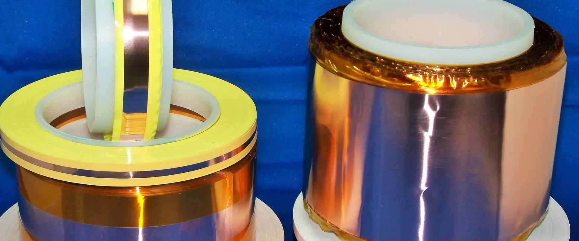
Copper

Out of the many radio frequency shielding materials in the market today, copper is the most reliable as per shielding performance. That is because copper is effective in terms of attenuating and absorbing the magnetic and electric components of EM waves hence it has the highest rf shielding performance. Moreover, it has impeccable electrical conductivity, which makes it perfect for this application.

Copper or CU is easy to produce. Moreover, you can easily manipulate it to form various shapes. Due to these reasons, shields made using copper tend to be pretty easy to install on various gadgets.

Additionally, copper is corrosive resistant, plus it can resist oxidation which occurs due to the environment.

Common copper alloy varieties that manufacturers utilize to build RF Interference shields include:

–          Bronze

–          Brass

–          Beryllium copper

–          Phosphorus bronze

Beryllium copper and phosphorus bronze have a unique elasticity feature, making them great for contact applications in springs and batteries.

However, even though copper has impeccable features that make it stand out, it is pretty expensive compared to other materials.

Nickel Silver

Nickel silver which also goes by the name copper alloy 770, is a widely utilized RF shielding material that contains the following components:

–          Zinc

–          Copper

–          Nickel

Nickel silver is primarily utilized in environments that are highly corrosive. Moreover, this material is pretty effective in terms of radiofrequency from mid-kilohertz to the gigahertz frequency range. Additionally, this component’s permeability stands at 1, which makes this material great for constructing radio frequency shields for MRI equipment.

Copper alloy 770 doesn’t need post-plating to become solderable and corrosion-resistant, making it great for RF shielding. Moreover, this component is highly aesthetic even though it doesn’t contain silver.

Aluminum

ESD shielding is required for FPC Design

Aluminum (Al) is a metal component that has a weight-to-strength ratio and impeccable electrical conductivity. Moreover, this material is pretty versatile.

Thin Al sheets are pretty efficient in terms of blocking low-RF waves. Due to this reason, aluminum tends to be utilized to generate RF shields for various electrical devices. However, the conductivity of aluminum tends to be 50 โ€“ 60% less than that of copper. Therefore, to achieve the shielding effectiveness of copper when utilizing aluminum, you have to make the shield thicker.

Moreover, aluminum tends to be pretty prone to oxidation and galvanic corrosion. Therefore, extensive exposure of Al RF shields to the environment might lead to oxidation on its surface. Moreover, the solderability of aluminum RF is also pretty poor.

Steel

Steel is produced in varying production processes, and it bears assorted alloy content. Moreover, steel and various ferromagnetic components offer low-frequency MF (magnetic field) shielding that lacks in both aluminum and copper alloy. Furthermore, these components possess multiple mechanical and RF shielding properties. However, this feature depends on the steel variety that you are using.

Low Carbon Steel

When compared with steel components that have high carbon levels, these steel variety has higher saturation and permeability. These properties tend to be crucial when drawing magnetic components of EM waves in radiofrequency shielding.

Annealed Steel

These steel variety has enhanced magnetic features when compared with other steel varieties. Generally, Annealing relieves the steel’s internal stress and enlarges the component’s grain structure.

Conclusion

For an electronic gadget to be regarded as functioning in an optimal manner, it has to be working correctly. However, RFI tends to decrease the device’s performance by making the device’s electrical circuit perform abnormally. However, using various RF shielding materials, you can quickly curb this issue before it drags down your device’s performance or makes it fail.

How to Create Smart Irrigation System Using Arduino

Smart Irrigation system using Arduino

The world keeps evolving and so are many things around it. Traditional irrigation was the irrigation system employed in those days. This irrigation system is overdue for a change in our world. The manual process of watering gardens and crops is a waste of time. This method of irrigation canโ€™t amount for any changes in soil or water that can affect the levels of moisture.

Also, several countries are experiencing water shortage. Irrigation water is as important as drinking water. Irrigation can result in water waste as this process requires a lot of water. Therefore, there is a need to find a lasting solution to this method of irrigation.  There is a need to bring irrigation to the next level. The lasting solution is the smart irrigation system.

Smart irrigation is a type of irrigation that accounts for the soil or weather conditions to define watering processes. This system optimizes irrigation for the particular area you are watering. This helps to save enough water and as well optimize the growth of the plants. In this article, we will be looking into smart irrigation system using Arduino.

What is Smart Irrigation System?

The smart irrigation system involves the use of technology and science to save water during irrigation. Also, smart irrigation involves the use of smart irrigation controller, weather sensors, and soil sensors. According to research, smart irrigation technology can minimize water waste by a whooping 40%. This irrigation system decides when to water plants and the amount of water needed based on the conditions of soil moisture.

The sensors integrated in this irrigation system monitors the actual ground humidity and weather conditions at present, while the controller regulates the water valve. The smart irrigation system can also be called automatic irrigation. This system judges when to water a plant and how much water is required. Therefore, it is ideal for water-saving management in landscape, farmland, lawn, and other areas.

Furthermore, smart irrigation system adopts technologies like remote sensing monitoring, the Internet of Things IoT, mobile Internet, and LORA. This irrigation system supplies the appropriate amount of water to plants based on weather conditions and soil type in order to save irrigation water. The smart irrigation system mainly incorporates different technologies like computer technology sensor technology, and automatic control technology. Also, it incorporates garden irrigation methods like drip irrigation and sprinkler irrigation.

Smart irrigation system waters plants without your help. This system offers a high level of precision. The software application behind the functioning of this system is Arduino. Arduino irrigation system is widely integrated in farms and gardens.

How the Smart Irrigation System Works

FULL PCB MANUFACTURING Quote

As it was earlier mentioned, the smart irrigation controller is one of the crucial components in this system. This controller is an advanced sensors that decides the frequency and amount of water for the system  based on either soil moisture or temperature  levels. Therefore, it is often regarded as the brain behind the entire irrigation system.

Due to the way weather-based controllers work, they are also called evapotranspiration. These controllers account for the expected transpiration and evaporation in a system to get weather information. This information helps them decide how often the the garden or lawn should be watered.

The three primary types of weather controllers are signal-based controllers, on-site controllers, and historic controllers. Also, these weather controller types are usually categorized according to the method used in obtaining their information:

  • Signal-based controllers: These controllers get their information from a public source and transfers it wirelessly to the controller.
  • On-site controllers: They use their own sensors to calculate the temperature, therefore, they respond to the particular temperature in the area.
  • Historic controllers: These controllers account for the historical water use in a particular region and function according to these averages.

Rather soil-based controllers depend on soil moisture. The smart irrigation system makes use of home Wifi or Lora for signal transmission. Also, this system can be controlled via a mobile phone or computer regardless of the location. The irrigator doesnโ€™t need to open or close the water valve manually. The operator places a sensor on the garden at a low level and determines the amount of water. This reveals how much water the soil contains.

What Does the Smart Irrigation System Comprise?

The composition of a smart irrigation system can  be complex since it features some powerful functions. This helps it to realize automatic water-saving irrigation. The smart irrigation system comprises terminal platform, monitoring part, transmission part, and control part. Each of these accessories works together to create a unit. These accessories have the following composition:

Monitoring part

The monitoring units for the smart irrigation system comprise different sensors. These sensors include leaf wetness sensor, soil moisture sensor, snow sensor, wind speed sensor, evaporation sensor, and data collector.

Control part

The basis for this irrigation system lies in different control valves. These valves offer support to remote switching which include ball valves, pulse valves, butterfly valves, etc. Therefore, it is crucial to various water pipes and valves based on different irrigation areas.

Transmission part

In the smart irrigation system, the control terminal and monitored terminal transmits the command signal and monitored data signal. If lora wireless transmission is being used in this process, the transmission part is the data concentrator. However, the transmission part is the monitoring host and the router if you are utilizing home WiFi.

Terminal platform

This is a software system for sorting and analyzing data. The terminal platform is capable of analyzing data, storing data and giving out control instructions. Also, this platform software offers support to the operations of a computer and mobile phone.

Different sensors send meteorological and soil moisture data to the platform. Then, this platform analyzes the data and studies it. Also, it analyzes the area and volume of water that requires irrigation, and then transmits wireless commands at every point. The controller regulates the opening and closing of the water valve. Also, it offers proper irrigation.

How Can you Make Smart Irrigation System Using Arduino?

Arduino is a popular and reliable development board for making smart irrigation system.  In this type of project, we will be using Arduino board, water pump, relay module, and moisture sensor. When you are planning to make a smart irrigation using Arduino, you need to ensure all the components you need are available. You will need to dip the soil moisture sensor inside the soil. Ensure you connect the water pump to a source of water supply.

The relay module will help you connect the water pump to the Arduino board. Arduino will use the soil moisture sensor to measure the moisture of the soil to determine if the soil is wet or not. The Arduino board will switch on the relay module if the soil is dry, the water pump will then turn on.

The water pump will be on until the soilโ€™s moisture level gets to a particular level. After it has achieved a certain level, the pump will go off.

Below are the components needed for smart irrigation system using Arduino

  • Arduino Uno
  • A soil moisture sensor
  • 9V battery
  • A breadboard
  • 30 Jumper wires
  • 5V DC water pump
  • Servo motor
  • Relay module

The Arduino UNO plays a crucial role. It regulates the motor pump based on soil moisture. You will need an external battery to power the circuit. Also, you can make use of 9v or 12v battery. You will connect the battery to the ground pins and Vin of Arduino. The motor can be connected to the battery through a relay. Connect the moisture sensor output to the Arduinoโ€™s analog pin.

Creating smart irrigation system using Arduino is very easy if you carry out the necessary steps.

Benefits of Smart Irrigation System with Arduino

Saves water

The smart irrigation system offers more accuracy and reduces water wastage. According to experts, this system conserves water across various scenarios. Research studies have revealed the substantial water saved by this system is around 30 to 50%. Smart irrigation systems save about 20% more water compared to traditional irrigation systems.

Presently, smart irrigation system using Arduino are reducing water wastage in agricultural production. Most farmers are interested in these systems because of the amount of water it saves.

Saves manpower

Smart irrigation system helps in saving manpower. This system uses automation to water plants. Therefore, there is no need to hire an irrigator to water the plant. Also, you donโ€™t need to open and close a water valve manually. You can carry out the irrigation task from your mobile phone. Also, it saves you the stress of worrying about your garden while you away.

Intelligent control

This system gives you an intelligent control over irrigation. It offers remote irrigation, time irrigation, and switching between the irrigation modes.

Conclusion

Smart irrigation system monitors soil moisture, weather, plant species and evaporation to adjust watering schedules. Also, this system reduces water wastage which occurs in traditional preset irrigation. Smart irrigation system using Arduino accounts for certain variables like sprinkler rates as rainfall changes or outdoor temperatures rise.  Also, they adjust the watering time constantly.

What are the Types of USB Ports Available?

types of USB ports

In the past it was difficult to connect devices to computers. Printers could only connect to parallel printer ports. Also, in those days, the computer featured one parallel printer port. This port offers limited success and less speed. However, the introduction of USB ports offered a long lasting solution to these problems

What are USB Ports?

USB ports are a cable connection interface designed for consumer electronic devices like computers. The full meaning of USB is Universal Serial Bus. USB ports enable connection between USB devices. They allow devices to connect and transmit digital data over USB cables. Also, the USB port is capable of supplying electric power through the cable to devices. This port allows you to charge a device.

The USB enables computers to interact with its peripheral and some devices. Devices connected to USB ย cover a very ย broad range. As technology advanced, USB ports are now more functional. Therefore, these ports paved way for lighter and smaller devices. There are three major things that matter in USB. These things are form factors, data transfer speed, video delivery, and power delivery.

Types of USB Ports

As regards form factors, there are different types of USB ports. Each of these USB ports has a unique use case and design. Micro-USB, USB-A, USB-C, and mini-USB are the commonest types of USB.

USB-A

If you are using the USB-A for the first time, you might find it difficult to plug it in correctly.  The USB- A is a rectangular and flat connector. These cables feature USB-A on one end having another type of port on the other. Also, this USB-A is specially designed for charging and transferring data between devices. You can still find USB-A in devices such as TVs, computers, gaming consoles, and different types of peripherals.

USB-B

These types of USB ports are widely integrated on large devices such as printers or scanners. This connector looks like square. Most connectors are USB-B to USB-A cables. However, some newer devices are now using smaller options such as Mini-USB or Micro-USB.

Micro-USB

These types of USB  ports were the major standard for some particular portable devices sometimes ago. They were  ideal for devices such as smartphones since this USB is capable of transferring data and offering charge. The Micro USB is available in Type-A Micro and Type-B Micro. Also, it is smaller when compared to USB-A. The micro-USB parts are still being used by some manufacturers for their devices since they are less expensive than the parts for USB-C.

Mini-USB

The mini-USB is similar to the USB-B, it is a smaller version. Before the introduction of Micro-USB, the mini-USB was the standard for data transfer from devices or charging. Also, this connector has its Type-B and Type-A versions. Today, you will hardly find products that integrate Mini-USB, although these types of USB ports are available in older electronics such as PlayStation3 controller or MP3 players.

USB-C

These types of USB ports  combine both power and data delivery alongside display connectivity. These types of USB ports are the current standard. They are widely integrated in most recent devices such as earbud cases, laptops,  smartphones, microphones, and game controllers. The form factor of this USB is reversible, small, and oblong, and as such, you can plug it in either way. This port features 100-watt connection which makes it suitable for data transfers and fast charging. It enables fast data transfer between larger devices.

USB-C ports offer more functionalities and benefits than other types of USB ports. Due to their unique multi-tasking abilities, these types of USB ports can replace all other cables. Also, they can power the most power-hungry devices such as TVs and computers. ย Also, they can transfer 40 gigabits of data at every second (Gbps). You can use these ports to deliver 4K video to external monitors.

Power Delivery of USB Ports

FULL PCB MANUFACTURING Quote

Some USB cables can supply power or transmit data, although the majority of USB cables can do both. When it comes to power delivery in USB ports, there are three main categories which are fast charge, fast charge, and power only.

The USB 3.0 enables 4.5W charging and USB 2.0 enables 2.5W charging. 10W can charge your phone slowly while 18W can charge your smartphone fast. The power delivery of USB is capable of handling about 100W. This can power devices such as dock stations, MacBook Pro, Tv, and monitors. Also, it is capable of charging compatible devices such as Nintendo Switch or phone.

Also, power delivery supplies the available charge to your device. However, it wonโ€™t overcharge it. More recent battery banks can now support USB PD. These battery banks can charge your power-hungry devices full.

USB Data Transfer Speed

USB are available in various size and shapes. Also, USB types feature multiple speed standards. It is important to know that some USB cables are only designed for data transfer while some can only deliver power. However, there are USB cables that serve the two purposes. Therefore, it is necessary to verify the abilities of a cable before you buy it.

USB 1.x was the first USB. This USB is extremely slow, and can only handle 1.5 Mbps. USB 2.0 is slightly old and charges slowly. However, it is still common. It is mostly available in older electronics. Also, USB 2.0 features a full-speed option that is capable of handling 12 Mbps, and a high-speed version is capable of handling 480 Mbps.

The USB 3.0 which is often regarded as SuperSpeed USB is an improved version of the USB 2.0. USB 3.0 offers increased performance and speed, better bandwidth capability, and better power management. This USB offers two unidirectional data paths for sending and receiving data. Also, it supports about 5.0 gigabits transfer rates per second.

USB 4.0, Thunderbolt 4, and Thunderbolt 3 are the most recent entries. In these entries, youโ€™ll  get the highest data transfer speeds. Also, these entries offer a maximum capable throughput of 40 Gbps. Another type of data transfer speed in standard in USB-C cables is Thunderbolt. All Thunderbolt 4 and Thunderbolt 3 cables are USB-C. However, some USB-C cables are not Thunderbolt. Therefore, you have to ensure the cable you are purchasing has Thunderbolt if that is what you need.

USB Video Delivery

The ability of a USB port to power a device and transmit data between devices is impressive enough. However, you can decide to integrate USB-C to link to monitors in place of a VGA cable or HDMI. Also, USB-C also offers support to 4K video delivery.

Thunderbolt 4 cables can display 4K content on two different monitors at a time. However, this may not be the use case for a vast number of people. You will need a cable that is capable if 8K and 4K video become more commonplace.

How Do USB Ports Work?

Computers usually feature one or more USB connectors. These USB connectors allow you to connect printers, mouse, keyboards, and other accessories to your computer. Also, the operating system of the computer supports USB. Therefore, the installation of the device drivers is very fast.

USB devices are very simple to connect compared to other connected devices like special cards and parallel ports that you install inside the case of a computer.

Also, modems made use of serial port. However, the majority of computers featured two serial ports at most. These serial ports were extremely slow. Some devices featured their own cards since they needed faster connections. These cards needed to fit inside a card slot in the case of computer. However, it is difficult to install some of these cards.  

USB was specially designed to put an end to all these headaches as it offers you a standardized and easy way to link about 127 devices to a computer. It is very easy and straightforward to connect a USB device. The USB connector is usually beside or at the back of your machine.

The operating system of a new device will detect the USB and request for the driver disk. If you have already installed the device, the computer will activate it and begins to interact with it. You can connect and disconnect USB devices at any time.

Most USB devices feature a built-in cable. This cable usually has an โ€œAโ€ connection. Otherwise, the device features a socket which accepts the USB โ€œBโ€ connector. Furthermore, the USB standard makes use of the โ€œA and โ€œBโ€ connectors to prevent any form of confusion.

What are USB Hubs?

The majority of computers available today feature at least two USB sockets. However, the availability of many USB devices today can make you run out of USB sockets. For instance, you could need to connect your mouse, printer, webcam, and keyboard to your computer. All of these devices are running on the USB technology. So, how do you connect all these devices?

The solution to this problem is to get an inexpensive USB hub. The USB standard supports about 127 devices. A hub features at least four new ports. All you need to do is to connect the hub to your computer and plug these devices. Also, you can plug in other hubs in this hub. You can create several USB ports on a computer by linking hubs.

You can power or unpower hubs. The USB standard enables devices to generate power from USB connection. Also, a high-power device such as scanner or printer will have its source of power supply. However, low-power devices such as digital cameras and mice can generate their power from the bus.

You donโ€™t need to power your hub if you have many self-powered devices. None of these devices require extra power, therefore, the computer is capable of handling it.

What are the Features of USB?

The USB comes with some features:

  • The computer is the host.
  • About 127 devices can be connected to the host, directly or by using many USB hubs.
  • The host computer can put several USB devices to sleep when it goes into a power-saving mode
  • Low power devices get power from the bus while high-power devices like printers feature their power supplies. Therefore, they get minimal power directly from the bus. Also, hubs can feature their power supplies to power devices attached to the hub.
  • USB devices can plugged into the bus and unplugged at any time.

Why USB Ports are now Replacing Serial Ports

USB provides three major benefits. It is better than serial ports in several ways.

Speed

USB ports enable the transmission of data at a much faster speed. They work ten times faster than the normal parallel port. Also, they are much faster than serial ports. On the average, a serial port offers a data transfer rate of 150kbps. On the other hand, the USB port offers about 12 Mbps. The data transmission rate depends on the types of USB ports. For instance, the maximum data transfer rate of USB 2.0 is 480 Mbps.

Compatibility

In the past few years, USB ports replaced serial ports. A wide range of industrial devices feature serial ports. This replacement is causing problems. USB ports are usually compatible with most USB devices.

Durability

USB ports are more durable than serial ports. The tiny little pins on serial ports can easily break or bend. USB ports, on the other hand, are very rugged. ย 

Frequently Asked Questions

How do you know if your USB cable is safe?

Ensure you make use of the USB cable featured by your device. Also, if you will be replacing your USB cable, always get it from the manufacturer of the device. However, if you need to buy from a third party, stick with a reliable brand.

What makes a USB port malfunction?

There are several reason your USB port may malfunction. This could be a result of a broken connection or an issue related with a software. Also, dirt in your USB ports could interfere with performance.

What can be plugged in a USB port?

You can plug several consumer electronics in a USB port. Most consumer electronics like TVs, smartphones, and radios support USB interfaces.

Conclusion

There are different types of USB ports and connectors. It is important to know these types of USB ports,  especially in these modern times when different devices feature various types of USB port. You will prevent any damage to your device by choosing the appropriate USB connector.

What is a CNC Machine and How Does it Aid Manufacturing?

What is a CNC

CNC means computer numerical control. CNC machines are widely integrated in the manufacturing industry as they play important roles. A computer controls the activities of these machines; therefore, they offer a level of consistency, efficiency, and accuracy. All this canโ€™t be achieved via a manual process.

CNC machines are completely different from โ€œold-schoolโ€ devices that are controlled manually by levers, or hand wheels. Todayโ€™s CNC machines understand the CNC machining language and function based on this. The CNC machining language is known as G-code. This language informs the machine about the precise measurements for production, such as coordination, speed, and feed rate.

In the 1940s and 1950s, the first CNC machines were developed. These machines depended on a common telecommunication data storage technology known as โ€œperforated paper tapeโ€ or โ€œpunched tape.โ€ However, punched tape technology has become obsolete as the data medium transformed to analog and digital computer processing. CNC machines kept improving their performance and efficiency as new technologies were introduced.

What is CNC Machining?

CNC Machine

CNC machining defines a process in manufacturing in which computer software controls the movement of machinery and factory tools. Also, this process can control several complex machinery, from lathes to grinders and CNC routers and mills. CNC machining helps in achieving three-dimensional cutting tasks in just a single set of prompts.

Therefore, this enables manufacturers to produce parts within a short time, minimize waste and get rid of the risk of human error. CNC is a computerized manufacturing process.

The CNC process functions in contrast to manual process and as such overcomes its limitations. In manual control process, live operators prompt and guide the machining tools through wheels, levers, and buttons. To a layman, a CNC system might look like computer components. However, CNC machining works differently from other forms of computation. This can be attributed to its integration of consoles and software programs.

How Does the CNC Machining Process Work?

Machining integrates a controlled material removal process to transform a piece of material like a block of plastic into a finished product. This process is very similar to a prototype development technology, FDM (3D printing. CNC functions based on digital instructions from a Computer-Aided Design (CAD) file such as Solidworks 3D. The CAD file offers the roadmap required for the CNC to create the design. The CNC machine then interprets these designs as instructions for cutting parts of a prototype.

CNC machining enhanced productivity by automating labor-intensive and highly technical processes through its ability to control machine tools through programming. Also, automated cuts enhance both the accuracy and the speed to create prototype parts, particularly for critical materials like polypropylene.

Machining processes usually integrate multiple tools to achieve the desired cuts. CNC machines combine tools into common cells or units from which the machine can make a drawing. Automated cuts are usually more accurate than cuts from manual inputs. When you activate a CNC system, the software programs the desired cuts and dictates corresponding machinery and tools which then perform the dimensional tasks as defined, just like a robot.

The code generator in CNC programming will often assume the mechanisms are without errors despite the possibility of errors. These errors may be more when you direct a CNC machine to cut in more than one direction at the same time. A series of input outlines how a tool is placed in a numerical control system.

Types of CNC Machines

FULL PCB MANUFACTURING Quote

The first CNC machines were developed in the 1940s. At this period, machine producers integrated motors to regulate pre-existing toolsโ€™ movement. However, these mechanisms enhanced as technologies advanced from analog computers to digital computers. Below are the most commonly used machines in CNC systems.

Lathes

Lathe machines integrate indexable tools to cut pieces in a circular direction. The introduction of CNC technology made it possible for lathes to make cut with high velocity and precision. Also, CNC lathes are widely integrated in producing complex designs that are impossible with manual machines. In general, lathes share similar control functions with CNC-run mills.

Lathes can make use of different tools to make precise cuts. Also, unique proprietary code or G-code can direct lathes. However, the majority of CNC lathes comprise two axes which are X and Z. CNC lathes offer more precision than manual lathes.

CNC plasma cutter

Plasma cutter integrates a plasma torch to cut a material. Also, plasma cutting is a common method employed to cut heavy materials like steel.  A CNC plasma cutter blows gas at a high speed from a nozzle. While doing this, the gas discharging from the nozzle to the surface that is being cut forms an electrical arc.

Therefore, some of the gas converts into plasma. Therefore, the temperature of the plasma ranges from about 10,000-50,000 degrees. In this case, the plasma becomes very hot and can melt whatever material that needs to be cut. After this, it blows away  molten metal from the cut.

CNC cutters have a similar appearance with CNC routers as regards size and shape. Also, CNC plasma cutters work only with two-dimensional shapes.

CNC milling machine

The CNC milling machine is one of the most commonly used CNC machines. This mill cuts different materials by integrating computer controls. Also, a CNC milling machine is capable of translating particular programs of letters and numbers to move the spindle in different ways. Most mills integrated a programming language called G-code.

Furthermore, a CNC milling machine can serve several purposes like shoulder milling, turning, face milling, and tapping. The majority of CNC mills are available in three to six-axis configurations.

Electric discharge machine

This machine uses electrical discharges to create a particular shape within a specific material. The electrical discharge machine removes the material from a particular work piece by several recurring electrical discharges between two electrodes. A dielectric fluid separates these two electrodes. This fluid receives an electric voltage.

The electric discharge machine places the material between two electrodes and then it calculates the amount of electrical discharge needed to be produces by each electrode. The electric field is more intense when there is a smaller space between the electrodes.

Water Jet cutter

This CNC machine can cut hard materials like metal and granite. It makes use of high-pressure from water. Sometimes, the water mixes with strong abrasive substance like sand. Manufacturing companies shape parts of factory machine with water jet cutter.

Water jets are usually integrated as a cooler option for materials that canโ€™t endure the heat-intensive processes of some CNC machines. Also, water jets are widely employed in mining and aerospace industries since they have cooler nature.

What is CNC Programming?

CNC machines integrate programming languages. Programming in CNC machines involves developing code for a computer to operate CNC tools and machines. The computer sends instructions to machines to carry out their tasks.

CNC programming enables manufacturers to automatically create parts while regulating the process manually. Also, CNC machines can convert raw materials into finished goods in large batches. Also, these machines offer great precision while doing this. Mass production can be more cost-efficient and more consistent with repeatable machine movements. This production process is better and faster than products made manually.

CNC machines can make products safer and stronger. Also, CNC machines can make it much easier to produce parts with 3D geometrics as computers are capable of handling the measurements and mathematical calculations.

Methods of CNC machine programming

There are three primary CNC machine programming methods. These are conversational, CAM, and manual system programming. When it comes to manual programming, the code is manually input. This process can be time-consuming and can require some efforts. Also, it requires having an intensive knowledge of the programming language. Manual programming is a foundational skill for operators. Also, it is a good way to carry out quick modifications to CAM outputs and as well optimize code.

The CAM system programming works in a similar way with the conversational method. However, it is more advanced. The software offers an advanced GUI in a CAM system. This helps the operator generate and prepare the program, thereby, getting rid of the need for manual programming.

All these methods of CNC machine programming involve M-code and G-code. The programming language that tells the CNC machine what to perform is the G-code. Also, this code enhances repeatable and accurate parts. On the other hand, M-code takes control over all of the miscellaneous CNC machine functions. Also, these codes are customizable and they vary based on the type of CNC machine. Therefore, programmers and programmers must be sure they are inputting the right functions before machining begins.

Types of Codes Integrated for CNC Programming

CNC

There are several codes used for CNC programming. Each of these codes has its specific function. Different letters are used to identify these codes. CNC programming codes instruct the machine on how, where and when to remove material from the stock. The most common types of CNC code includes:

D-code

This code is the tool offset of the CNC machine. It can be the distance the tool sticks out from the tool holder.

G-code

This means โ€œGeometryโ€ code. G-code tells the machine where, how, and when to move between two points.

N-code

N-code is a block of machine code or identify line. This line labels some parts which helps the programmer to follow written CNC code.

T-code

This code is ideal for use when machining a particular feature on the workpiece.

F-code

This code describes the various speeds at which the machine should move while cutting. The F-code is a feed rate code.

How Do You Write CNC Codes?

It is very easy to write CNC codes if you follow the necessary steps.  However, you need to be familiar with some principles of CNC machining. Having a good understanding of the functions and features of CNC tools is important to optimizing the best speed settings. Below are steps on how to write CNC codes:

Export 3D model

You can export the CAD model in the CAM software first. However, you might not need to export since some CAD systems have CAM capabilities.

Create tool paths

You can transform the CAD model into tool paths manually or by allowing the CAM software produce the tool paths.

Verify tool paths

You need to confirm that the tool paths are accurate. You can do this by simulating the tool paths or manually.

Download code to CNC machine

You need to input the G-code in the machine. A portable storage device can help you achieve this process. Alternatively, you can download the code to the machine.

Tips for CNC Machine Programming

Revisit the basics

CNC programmers and machinists should master the basics before beginning any project. Conversational and manual programmers need to cross-check their mathematical calculation to be sure the right specifications are being programmed in the CNC machine. Also, it is important that programmers know that CNC software is fallible.

Simplify CNC machine programming

For the majority of CNC machining programs, G-codes are the standard programming code. But, it can take a lot of time to program operations. Therefore, CNC machine operators can use canned cycles to reduce the programming of hole-machining operations.

Canned cycles only need a block for each hole, irrespective of the machining style. Operator can machine extra holes by programming the holeโ€™s coordinates again once he inputs a canned cycle. Codes such as G83 minimize errors, make programming easier, and save time.

Customize CNC machine feed rates

Operators usually spend time to dial a program to be certain that it runs consistently and smoothly. Immediately they accomplish this and they lock the program, they can โ€œset it and forget it.โ€ Operators can optimize manufacturing by simply customizing particular parts of CNC machining.

Understand types of CNC machine compensation

Compensation is CNC machine programming enables and accounts for the occurrence of unpredictable variations. Also, it is possible for an operator to input CNC programming codes or calculate the values that should produce the perfect part. However, they can only confirm the precision and accuracy of programming until they have completed machining.

Conclusion

The CNC process functions in contrast to manual process and as such overcomes its limitations. In the manual control process, live operators prompt and guide the machining tools through wheels, levers, and buttons.

What is a Relay and what is its Significance?

What is a Relay

Although it is a difficult process, turning a low-current electrical input to an output of high current is needed to utilize a variety of common products and vehicles effectively. Relays, which are essential in all types of different electronic equipment, are used in many circuits to accomplish these conversions.

What is a Relay?

Relays are electrical switches that transform weak electrical inputs into stronger currents through the use of electromagnetism. These transformations take place whenever electrical inputs cause electromagnets to break or build circuits in response to electrical inputs.

Relays essentially function as either an amplifier or a switch for an electric circuit, based on the intended application, by using weak inputs for powering higher currents.

Why Would You Use a Relay?

Relays are incredibly adaptable parts that work equally well in both simple and complex circuits. They can replace other types of switches or be specifically created based on requirements like necessary voltage.

Switching Current Level

The requirement to go from low to high current (and vice versa) inside a circuit is a frequent scenario that calls for the employment of the relay.

For instance, the HVAC systems’ temperature sensors require amounts of amperage well in excess of what their wiring can handle. Relays offer the required amplification to increase a tiny current’s size.

Complex Applications

These relays can do more than just convert one input into one output at different single points present in a circuit.

Secondary applications allow a single input to start numerous other effects thanks to the ability of one relay to activate many circuits.

Relays can also be employed in conjunction with each other to carry out Boolean logic operations that, while they can be carried out utilizing different components, might be more affordable when relays are utilized.

Furthermore, certain relays have more sophisticated capabilities than other types of electronic components. For example, time delay relays let systems run for a predetermined amount of time or start just after a predetermined amount of time.

It opens up more complex options for developing electronic systems.

Advantages of a Relay

FULL PCB MANUFACTURING Quote

Employing a relay might be helpful even if the application doesn’t clearly call for one. High-amperage wiring as well as switches may not be necessary with the use of relays, which are costly and takes up much space.

As a result, switching to the relays in the electrical systems can enable manufacturers to include additional functionality to a space having the same size or lower the weight or size of the casing.

How Do Relays Work?  

Capacity, size, as well as corresponding uses of relays vary. Nevertheless, despite these differences, all relays work in basically similar ways: one circuit powers another. Depending upon whether the relay remains normally open or closed, this can happen in a variety of ways. ย 

Normally Opened Relays

Many relays are ordinarily open, which means that the second and larger circuit gets typically turned off. An electromagnet is activated by power passing via the input circuit of a usually open relay.

As a result, a contact is drawn to the other, larger circuit, creating a magnetic field which attracts it and enables current to pass through. The spring draws away the contact from this second circuit when the power supply is cut off, cutting off the electricity flow and shutting off the device.

Standard Closed Relays

A NC (not closed) relay operates similarly to a NO (not opened) relay in that it has two circuits, the second of which is larger, and it uses an electromagnet to shift the physical contact in-between the two locations.

However, its default states become the opposite for the NC relay. The electromagnet pulls this contact away out of your second circuit whenever the initial circuit is turned on. NC relays maintain the larger circuit’s on state as a result.

How to Spot a Malfunctioning Relay

relay-circuit-board

Relays, despite being generally reliable, are susceptible to mechanical failure. Fortunately, utilizing a multimeter to find a defective relay is not too difficult.

To do this, you should first find the locations of the circuits within and outside the relay, which are frequently indicated by pins. You can utilize the multimeter for gauging this voltage present at every site after locating it.

Use the troubleshooting methods listed below:

  • Verify that there is voltage where this relay is plugged in. When there isn’t, look for problems with the switch or fuse.
  • When there is a voltage present at the point of connection, utilize the continuity feature on your multimeter to check if the relay’s other side has a solid ground connection.
  • Check its voltage at that location where its relay attaches to a battery or another power source if the first two steps above are unsuccessful in identifying the issue’s root cause. Should there be no voltage at this location, a circuit breaker or fuse may be faulty.
  • Lastly, use the multimeter’s continuity function to check that there is a good connection between this relay as well as the component. It might be time for you to replace this relay if a connection is present and the previous stages did not indicate a different problem.  

How Many Relay Types are There?

There are numerous varieties of relays, and each one serves a different purpose in a range of applications. Several of the more general types are:

Time-Delay Relays

Relays with a time delay come in handy when a component needs to be operated for a predetermined period of time as well as after a predetermined delay. The relays are ideal for a variety of applications that are time based since they provide built-in time-delay capability.

There are various time-delay relay types included in this category, and each has a unique use.

One of the two main categories can be used to group the majority of time-delay relays:

Whenever this input has been applied, on-delay timers start timing and power the 2nd circuit after the predetermined amount of waiting. This could be used for applications including warning and alarm systems, to prevent power surges, to stagger its powering of different components, or both.

Off-delay timers keep the input active until a trigger is received. The output gets energized when the trigger gets released, and after this time delay, it de-energizes. The delay is reset when the trigger is reapplied. In cycles for the dryer and washer or on rides at amusement parks, these relays could be utilized to power equipment for predetermined durations.

With flashers, repeat cycles, or one-shot timers additional start as well as delay patterns are possible. With each of these, the component can be energized at various repeating intervals. It permits some kinds of scheduled cycles as well as flashing indication or the warning lights.

Sequential Relays

Multiple components can be powered sequentially, often in a predetermined order, through relays. Using this kind of relay to power several systems and light sets one by one like in sequencing of power supply or runway lights is a typical use.

Automotive Relays

Relays are used in a wide variety of automobile applications, which include majority of the types of relay mentioned. Numerous automotive relays enable designers to incorporate cutting-edge security measures and contemporary electrical comforts.

Relays are used to power these systems in typical trucks or cars, just to name some examples: Gas valves, alarm systems, windshield wipers, headlights, interior lighting, , and warning devices for seatbelt use, weight restrictions, and hazard detection.

Applications of Relay

Relays are utilized to safeguard its electrical system as well as reduce damage to connected equipment from overcurrents and overvoltages. The relay is used to protect the equipment that is linked to it.

With the help of low voltage signals, these are utilized to operate high voltage circuits in devices like audio amplifiers as well as some kinds of modems.

They are utilized in applications including starter solenoids in automobiles to control the circuit of high current by the signal of low current. These are capable of identifying and isolating faults in the power transmission as well as distribution system.

Relays typically find use in the following areas: computer interfaces, home appliances, automotive, industrial process controller, telecommunication, motor drive control, traffic control, and systems for lighting control systems.

How is a Relay Tested?

Relays are unique electromechanical devices, therefore they ultimately wear out a as well as quit functioning. However, there aren’t many methods for determining whether a relay is operational.

These methods include:

  • Multimeter testing for relays
  • Create a straightforward circuit for testing the relay;
  • Check the relay’s operation using the direct current power supply.

Where Can You Find Your Next Relay?

Relays are a crucial component of the circuit design, therefore it’s important to get high-quality relays that are the right type as well as size that suits your application.

Relays as well as other electronic parts from us are available in a variety of styles that can save you time, energy, and money. We also focus on designing items specifically for you in order to solve your personal concerns.

Unleashing the Power of Raspberry Pi 400

Raspberry pi into a Router

The mission of the Raspberry Pi Company is to deliver quality and affordable computing to every person, wherever they are in the world. And true to its word, this company has gone a pretty long way in terms of trying to deliver on its promise via affordable kits which bundle a mouse and keyboard for a complete computing experience for their users.

But how about a Pi gadget that is built inside a keyboard? After all, Pi developers have previously installed this device inside storage centers, media centers, and even laptop cases. However, all these examples are projects done for third parties and not for the company, in particular, to supply to Pi users. Moreover, these projects involve taking already-made raspberry Pi circuit boards off the shelf and then integrating them inside new hardware components. But what if the raspberry developers found a way to redesign these boards and incorporate them inside their own official raspberry pi keyboard? That is precisely what the Raspberry Pi 400 is all about. ย However, the raspberry pi 400 also has some cool features that make it stand out.

What is a Raspberry Pi and its Connection to PCBs?

Printed Circuit Boards, or PCBs, are electronic assemblies that utilize copper conductors to generate electrical connections between various electronic components. Moreover, PCBs offer mechanical support to various electrical components so that the devices can be efficiently mounted in enclosures.

PCBs include conductive features such as:

  • Conductive planes
  • Pads
  • Copper traces

Moreover, the boardโ€™s mechanical structure tends to be generated using insulating components which are laminated between the conductor layers. Additionally, the overall circuit board structure is then plated, after which a solder mask is applied, followed by a silk screen utilized to imprint crucial information on the board, such as the company’s logo.

On the other hand, a raspberry pi printed circuit board is simply a PCB that bears a combo of castellated holes and through-holes with pitch pin headers. In other words, the raspberry pi circuit board is a complex computer board that is pretty small. The raspberry pi is actually as small as a credit card. Therefore it is pretty portable. However, it is also pretty powerful and efficient.

The Raspberry Pi 400

Can a person really purchase a fully functioning PC for as little as 70 USD? Most people ask themselves this question whenever they hear about raspberry pi gadgets. However, the answer to that question is yes. By utilizing the all-in-one PC design, which manufacturers were using in the classic 1990s and 1980s home computer, the raspberry pi company has found a way to integrate a raspberry pi gadget inside their official keyboard.

The raspberry pi 400 devices are integrated inside keyboards which means that all you have to do to utilize these devices is connect the keyboard to a TV or monitor via an HDMI socket, and you are done. Moreover, based on its quad-core chip, the raspberry pi 400 can efficiently host various desktop apps in the raspberry pi operating system, which is Linux based.

The Hardware Components of the Raspberry Pi 400

FULL PCB MANUFACTURING Quote

On paper, raspberry pi 400 specifications (specs) might not compare well with most entry-level laptop and desktop computers. However, these devices are affordable compared to laptops and desktop computers.

Inside, the raspberry pi 400 is typically a modified raspberry 4 version. That is because these devices utilize the same BCM2711 Broadcom SoC, which quad-core cortex-A72 64-bit processors power. Moreover, these processors clock 1.8 gigahertz by default, though by making some modifications, you can increase this to about 2.2 gigahertz.

Additionally, the raspberry 400 comes with 4 gigabytes of Ram, which means that it canโ€™t match the raspberry pi 4 in terms of performance since the pi 4 version comes with 8 gigabytes of ram. However, the raspberry pi 400 is still very fast. It is around 40 times more powerful than the first Pi model, which hit the market in 2012.

The compact keyboard of the raspberry pi 400 features various Chiclet keys.  These keys include the unique raspberry pi key, which pops up the pi’s desktop menu on the monitor when you click it. Moreover, you can easily power up or down your raspberry gadget by utilizing a unique combo of buttons (Fn + F10).

Raspberry pi manufacturers can supply the pi 400 with various international keyboard layouts. Therefore, you can select the keyboard layout you like, and the company will deliver the raspberry pi 400 in a keyboard bearing that layout.

Ports

At the board’s rear side, you will find 3 USB-A ports which you can utilize to connect peripheral gadgets such as:

  • A mouse
  • External storage gadgets

Moreover, just like in most raspberry pi models, the pi 400 has a microSD card slot that you can utilize to host the board’s storage and operating system. In addition, however, you can opt to use an SDD since it offers improved performance.

On the other hand, the pi 400 also comes with two micro HDMI ports, which you can utilize to connect at most two displays. Moreover, the HDMI ports provide a resolution of 4Kp60. However, to connect the pi 400 to a display, you will require a micro HDMI to HDMI connector cable.

Other ports that you will find on the raspberry 400 include the following:

  • A USB-C port for power utilizes the 15 watts official raspberry pi PSU which is supplied separately.
  • A Gigabit Ethernet port – However, most people prefer to utilize the in-built dual-band wireless functionality for Wi-FI.
  • Bluetooth 5.0 BLE โ€“ you can use this feature to connect to nearby devices easily.

However, on the downside, raspberry pi 400s lack the popular 3.5-millimeter AV port. Moreover, the raspberry pi 400 also lacks display and camera connectors which are found in full-size pi circuit boards. However, these boards come with 40-pin general-purpose output and input headers on the rear, like in other pi models. Using these GPIO headers, you can easily connect add-on boards and electronics.

PC Kit

If you are planning on purchasing a Raspberry Pi 400, there are a few things that you should keep in mind. Firstly, the standalone 70 USD raspberry pi 400 does not come with the following components:

  • MicroSD cards
  • HDMI Cable
  • Mouse
  • PSU

But you can purchase these components separately. However, you can get all these components plus a beginner guidebook on raspberry pi 400 in the kit bundle of pi 400 that will only cost you 100 USD.

Operating System

Raspberry Pi 3A+
Raspberry Pi 3A+

Like all other pi computers, by default, raspberry pi 400 computers host their OS on microSD cards. Moreover, these microSD cards also double down as the boardโ€™s storage.

In most cases, you will find raspberry pi computers utilizing the official pi operating system based on Linux (Debian version). However, you can still install other OS versions, such as:

  • Ubuntu
  • Specialist OSes โ€“ which come in handy if you are a retro gamer

Moreover, by slightly manipulating the pi 400, you can even install and use windows 10. However, compared to other operating systems, windows is not very efficient on a raspberry pi 400.

All versions of Pi operating systems installable via the Pi Imager card flashing tools are 32-bit. However, the company is working on a version that will run on 64 bits. The 64 bits OS version will run efficiently on both raspberry pi four and raspberry pi 400.

Desktop Software and Environment

The standard version of the Pi operating system has a GUI (graphical user interface) that sorts various apps into categories. Moreover, by default, raspberry pi comes bearing a few applications, which include an email application. However, you can still install more applications on the computer for free via recommended software tools.  

Available apps include the complete LibreOffice suite, which bears the following elements:

  • A presentation software
  • A spreadsheet software
  • And word processing software

Programming and Electronics

The core applications of the raspberry pi 400 include:

  • Thonny IDE, which users utilize for programming purposes
  • Scratch, which is a block-based programming tool

Using these two applications, you can effectively utilize the GPIO headers of the pi 400 to communicate with various components, such as the board’s pins and electronic circuitry. With this power in your hands, you can make multiple manipulations on the board to make it cooler or more efficient. Moreover, this feature also lets you utilize the pi 400 like an Arduino.  

Additionally, you can connect expansion boards, often referred to as HATs, to the board’s GPIO headers. However, one problem with integrating HATs is that even though they function correctly, the pi board will have to face toward the rear side. Therefore, if the board has any type of display, users can’t see it. However, you can simply install the HATs using 40-pin ribbon wires to get around this issue.

ย 

Pros of Using a Raspberry Pi 400

The raspberry pi 400 has multiple advantages, which include:

  • A faster processor
  • The raspberry pi is installed inside a keyboard, making it pretty compact and efficient.
  • An available kit that has everything that you need to run your pi 400

Cons

Even though the raspberry pi 400 is efficient, it still has some disadvantages, which include:

  • Not having an audio-out jack
  • Lacking some ports which are found on other raspberry pi versions
  • Not fitting all HATs

Conclusion

If you are looking for an affordable computer to use for browsing, coding, or basic productivity suites, then the pi 400 is a solution worth trying out. The raspberry pi 400 has a simple installation process, is pretty easy to utilize, and makes a tremendously credible Linux PC. Therefore, we hope this article has provided you with all the answers you were looking for regarding the raspberry pi 400.

The Importance of Capacitance Formula in Engineering Applications

Capacitance Formula

Capacitors are specially designed to store energy by holding opposite charges apart. These two-terminal devices are capable of storing energy. On the other hand, capacitance measures the ability of a capacitor to store energy.

The capacitance formula is needed to calculate capacitance. Also, there are various applications of the capacitance formula. This formula is applied in some engineering applications. Also, the capacitance formula is crucial in calculating some things related to capacitance.

What is Capacitance?

Capacitance refers to the capability of a circuit to absorb and store energy in an electrical charge form. Also, capacitance is an electrical property that determines how much energy is stored in a capacitor. The unit of capacitance is Farad (F).

Furthermore, capacitance is usually expressed electric chargeโ€™s ratio on each conductor to the possible difference between them. Farads (F) represent the capacitance value of a capacitor. This was named after an English physicist Michael Faraday.

A farad represents a large quantity of capacitance. The majority of household electrical appliances have capacitors that generate just a fraction of a farad often known as microfarad. Microfarad represents a thousandth of a farad while nanofarad is a unit of capacitance that represent a billionth of a farad. Picofarad represents a trillionth of a farad. To have a better understanding, the units of capacitance include;

Picofarad (pF) 1pF=1/1,000,000,000

Nanofarad (nF) 1nF=1/1,000,000,000

Microfarad (ฮผF) 1ฮผF=1/1,000,000

On the other hand, Supercapacitors are capable of storing large electrical charges. Supercapacitors feature high capacitance which is about 2kF. Also, these capacitors are capable of storing large amounts of energy. They provide advanced technological possibilities in applications such as regenerative braking in automobiles and electrical motors.

What are Capacitors?

Capacitors are electronic components that store are energy. They are usually available in a wide range of shapes and sizes. Furthermore, they comprise two plates of conducting material which is usually sandwiched between an insulator made of materials like glass, film, and ceramic. A capacitor can store electrical charge and electrical energy.

The insulator is an electronic component that enhances the charging capacity of a capacitor. It is also known as a dielectric. The aviation, automotive and marine industries sometimes refer to capacitors as condensers in the automotive, marine and aviation industries. The internal plates of the capacitor are usually wired to two outer terminals. You can plug these terminals into a circuit.

Furthermore, batteries and capacitors store energy. However, capacitors quickly discharge energy while batteries gradually release energy.

Generally, capacitors have two electrical conductors in which distance separates them. These electrical conductors can sometimes be called โ€œelectrodes.โ€However,  they are widely known as more correctly, โ€œcapacitor plates.โ€Also, if the space between capacitors is a vacuum, such a capacitor is referred to as a โ€œvacuum capacitor.โ€

However, a dielectric usually fills up the space. The dielectric is simply an insulating material. Capacitance determines how much energy is stored in a capacitor. Capacitors serves various functions ranging from radio reception to filtering static and storage of energy in heart defibrillators. Commercial capacitors usually comprise two conducting parts which are close to one another but not in contact.

Most times, engineers use a dielectric is used between the two plates. The battery moves some amount of charge of magnitude Q to the negative plate when you connect battery terminals to an initially uncharged capacitor.

How Do Capacitors Work?

FULL PCB MANUFACTURING Quote

To have a better understanding of how capacitors work, we will need to take the most basic structure of a capacitor into consideration.  Parallel plate capacitor can be described as the most basic structure of a capacitor. It comprises two parallel plates in which a dielectric separates them.

One plate (plate I) connects to the positive end while the other plate (Plate II) connects to the negative end when a DC voltage source is connected across the capacitor. The plate I is positive in respect to the second plate when you apply the battery potential across the capacitor. At this point, the current attempts to pass through the capacitor from its positive plate to its negative plate. However, it cannot pass through since an insulating material is separating the plates.

There is an electric field across the capacitor. Plate I will store positive charges from the battery while the plate II which connects to the negative end stores negative charges from the battery.  At a point in time, the capacitor will absorb the highest amount of charge as regards its capacitance in accordance to this voltage. This time span is usually referred to as the capacitorโ€™s charging time.

The two plates will hold a positive and negative charge for a particular period when you remove the battery from the capacitor. Therefore, the capacitor functions as a source of electrical energy.

What are the Functions of Capacitors?

Capacitors serve various functions. Therefore, they are widely used in various applications and circuits like preventing the flow of DC current while allowing the transmission of audio signals, pulses, or other time different wave forms. The ability of capacitors to prevent the flow of DC currents makes capacitors ideal for smoothing out the output voltages of power supplies.

Also, capacitors can get rid of unwanted spikes that are in signals which could cause damage to components. These unwanted spikes could result in false triggering of digital components. Capacitors can as well help in adjusting an audio circuitsโ€™ frequency response. These components can couple together individual amplifier stages that need protection from DC currentโ€™s transmission.

A capacitor features infinite impedance when integrated on DC supplies. However, it features no impedance when integrated at extremely high frequencies. Also, it is important to know that all capacitors feature a maximum working DC voltage rating. Therefore, ensure you select a capacitor that has a higher voltage rating than the supply voltage.

Capacitors function as sensors. In this case, they measure various things which include fuel levels, humidity, and mechanical strain. Furthermore, capacitors condition power supplies. They enable the flow of AC signals when charged, thereby, preventing the flow of DC signals. A capacitor helps to decouple different parts of a circuit. This helps to minimize noise due to increasing efficiency. In utility substations, capacitors play a crucial role as they counteract inductive loading caused by transmission lines.

Capacitor Formula

Capacitors have many equations and calculation. To get the value of capacitance, you need to know the capacitor formula. The capacitor reactance equations are very common. However, you need to perform more capacitor calculations.

Capacitor calculations and capacitor equation have several aspects of capacitor operation. This includes the capacitance reactance calculations, capacitor charge, and more. The basic capacitor equation or capacitor formula is very useful in several areas of electronic circuit design. These calculations may seem useful only for theoretical purposes, but these calculations can also be useful in practical scenarios.

What is the Basic Capacitance Formula?

Capacitors in Series

Basic capacitor equations connect the capacitance with the charge the capacitor is holding. Capacitance is simply the capability of an electronic component to absorb and store energy in the form of an electrical charge. Also, it is how much electric charge a conductor can store for a defined difference in electric potential.

The basic equation for capacitance is C=Q/V

In this equation:

  • C represents capacitance in Farads
  • Q represents the charge on the plates
  • V represents the possible difference across the plates

It is crucial to always know the basic equation for capacitance. This is because it is usually integrated in a wide range of electrical circuit design. You can always remember this equation by using a memory triangle.

How to Calculate Capacitance of a Parallel Plate Capacitor

The calculation of the capacitance of a parallel plate capacitor is another basic calculations associated with capacitance. With the formula that was earlier given, you can predict the capacitance of a capacitor based on the area of the plates or the dielectric constant (Dk) between the two plates.

You can understand the levels of stray capacitance on PCBs and other aspects of electronic circuit design by using this basic theory and equation. As the speeds on electronic circuits keep rising fast as the technology for ICs , the levels of stray capacitance of the tracks increases and this can have a significant impact on the operation of the circuit. Therefore, it is important to take this factor into account for many circuit designs.

We can deduce capacitance equation below;

C=ฮตr  ฮต0  A/d

Where

 C is the capacitance

ฮตr  is the relative permittivity for that medium

ฮต0  is the permittivity of space

A is the area of one plate

d is the distance between two plates

It is important to calculate the capacitance of a plate capacitor where you need to make use of flat capacitors. However, it is crucial to calculate the capacitance for a tubular capacitor.

How to Calculate the amount of Energy Stored in a Capacitor

Calculating the energy stored in a capacitor is another crucial equation related with capacitors. The amount of energy in the capacitors equals the work needed to pace the charge in a capacitor.

The energy stored in a capacitor is calculated using the formula;

W=โˆซQ0V dQ 

W=โˆซQ0qC dQ 

W=12CV2

These formulae are important to determine the charge level in a capacitor. They are widely used in several areas of electronic circuit design. Also, calculating the amount of energy stored in a capacitor can be very useful in various scenarios like power supply design.

The capacitance equation helps in calculating the levels if capacitance and as well as the stored energy in them.

Voltage Rating in Capacitors

There is a maximum voltage rating in all capacitors. Therefore, you need to consider the amount of voltage applied to the capacitor when selecting a capacitor. The highest amount of voltage you can apply to the capacitor without any form of damage to its dielectric material is given as: WV DC, (DC working voltage).

There will be a breakdown in the dielectric if high voltage is applied across the capacitor. This is usually referred to as electrical breakdown. The breakdown will result in arcing between the capacitor plates and as such there is a short-circuit. The thickness of the dielectric material and the type of dielectric material determine the capacitorโ€™s working voltage.

Dielectric leakage is another crucial factor that has a direct impact on the operation of a capacitor. Also, dielectric leakage occurs when an unwanted leakage current moves through the dielectric material. It is usually assumed that the dielectricโ€™s resistance is very high and the dielectric is a good insulator that prevents the flow of DC current via the capacitor from one plate to another.

If excessive temperature or voltage causes a damage to the dielectric material becomes, this will result in a high leakage current flowing through the dielectric. Therefore, this makes the plates to loose charge quickly and also an overheating of the capacitor which causes the capacitor to have premature failure in the long run. Avoid using a capacitor in a circuit whose voltages are higher than the capacitor it is rated for. Otherwise, the capacitor may explode due to overheating.

Frequently Asked Questions

What is a variable capacitor?

The capacitance of a variable capacitor can vary to a particular range of values depending on necessity. A variable capacitor has two plates in which these plates are made of metals. One of the plates is movable while the other is fixed.

What type of energy does a capacitor store?

Electrical potential energy is the energy stored in a capacitor, which is related to the voltage V and charge Q on the capacitor.

How do you calculate the capacitance of a spherical capacitor?

A spherical capacitor comprises concentric conducting spherical shells of Radii R1 and R2. R1 has +Q while R2 has โ€“Q charges. The electric field between these shells are radially outward.

The capacitance formula of a spherical capacitor is

C=4ฯ€ฯต0โ€‹R1โ€‹R2โ€‹โ€‹/R2-R1

With this capacitance equation, you can calculate the capacitance of a spherical capacitor.

Conclusion

A capacitor features infinite impedance when integrated on DC supplies. However, it features no impedance when integrated at extremely high frequencies. Capacitance is an electrical property that determines how much energy is stored in a capacitor. The unit of capacitance is Farad (F).

How to discharge a capacitor

How to Discharge a Capacitor

A capacitor can be described as a tool for storing electrical energy. By generating electric field in-between the two plates, it does this. The capacitor charges when it receives a voltage.

The capacitor is measured by its capacitance, which is often expressed in farads. In AC circuits, capacitors function as rechargeable batteries. They serve the purpose for which they were designed, which is to store electrical energy as well as transmit it to the other components of your circuit.

Why Is It Necessary To Discharge Capacitors?

As we previously stated, capacitors serve as energy storage devices and can shock you severely if you handle them when they are still charged. To discharge these capacitors first before handling them is crucial.

After this current stops passing via the circuit, they can retain this current in them for some minutes. We must always release them before you work because of this.

What Capacitors Are Generally Recognized as Safe?

Discharge a Capacitor

This query has no answer. Any capacitor has some degree of potential harm. However, capacitors with a voltage of about 50 volts canโ€™t send current via the body as well as result in death.

Smaller-than-50V capacitors frequently result in stinging, minor electrical shocks, and a faint tingling in the fingertips. They are relatively safe in our opinion.

Keep in mind that just empty capacitors remain completely secure.

Precautions to Take Before Discharging a Capacitor

Remove the capacitor out from its electrical source

  • You should first turn off the supply of power before we will be able to explain how to discharge a capacitor.
  • If the gadget is within the house, it can be unplugged from the power socket; when it’s in your car, you must unplug the wires that are attached to the – and + terminals of your car battery.
  • Disable your power line and turn off any equipment that is powered by an external battery and an independent power source.

Put on safety gear

When discharging a capacitor, it’s crucial to wear protective gear for some reasons. One explanation is because capacitors have a high energy storage capacity and can spark when they begin to discharge.

Another factor is that when a capacitor’s metal contacts make contact with skin, they might cause electric shocks.

Most individuals find wearing protective gear amusing, but whenever they are hurt by sparks or electric shock, they have a change of heart. Gloves and goggles, for example, can assist shield you from such dangers.

Safe environments

Before emptying the capacitor, make sure the area is free of any objects or materials that could catch fire.

Different Techniques on How to Discharge a Capacitor

FULL PCB MANUFACTURING Quote

How to Discharge a Capacitor Using a Screwdriver

Disconnect the power source

Always cut off the source of power before discharging capacitors while working with them. Injury and accident prevention will benefit from this. Energy can be stored in capacitors in vast quantities.

On your electronic equipment, locate your capacitor

Capacitors are typically found close to the power source since they are known for energy storage as well as the regulation of current flow.

If you’re having trouble locating the capacitor, go to the owner’s manual or the schematic diagram.

Locate the negative and positive terminals of the capacitor

Wearing gloves, grab the body’s condenser without contacting the terminals on the feet. The electrical circuit’s negative and positive connectors are represented by these metal contacts.

To join terminals together, use the insulated screwdriver

Use the insulated screwdriver when discharging the capacitor to prevent coming into contact with its live contacts.

Determine the capacitor’s negative and positive terminals first. Use the insulated screwdriver to connect the negative and positive terminals after that. Until this capacitor discharges, hold your screwdriver there for a short period of time. A brief sound flash or spark can result from capacitor discharge. Don’t be scared as it is normal.

Take out the screwdriver out from terminals of the capacitor

To confirm that it’s empty, repeat the initial step. Simply remove the screwdriver out from its terminals after that. To measure the voltage, connect a multimeter.

Capacitor voltage should be measured using a multimeter

Connect the metal connections and probes. It doesn’t matter how the connections are made (the polarity).

If you obtain a value greater than zero, your capacitor has not been discharged entirely, and you should repeat the process a few more times to be sure that it has.

How to Discharge a Capacitor Using the Pen Tool

PCB Capacitor

The pen tool can be used to shorten out a capacitor’s two plates in order to discharge it. This will produce a spark, immediately releasing the energy. Make sure you discharge capacitors with caution, because they have the ability to store significant energy.

The simplest and quickest method is this. A resistor with high-value built into a discharging tool enables fast current discharge.

How to Discharge a Capacitor Using a Light Bulb

This third method involves using the light bulb. You can use the light bulb if you do not have a screwdriver or discharge tool at home.

  • You must take a single light bulb which is wired to the bulb socket.
  • Join the positive termination of one of its wires to the negative terminal of the second wire. When the light goes out, it implies the capacitor has gone empty. The bulb would start to come on.

The bulb has the benefit of having the light pointer which indicates when this capacitor becomes full empty.

How to Discharge a Capacitor Using a Resistor

  • Verify that the capacitor has been unplugged and not receiving any electricity.
  • Cross the capacitor’s terminals with its high-value resistors.
  • Place the resistor’s ends in contact with the capacitor’s metal contacts.
  • Let the capacitor discharge completely.
  • Cut the resistor’s connection to the capacitor.
  • Turn on the capacitor by plugging it in.

The capacitor is shielded from potential damage by the resistor, which stops a high surge in current from passing through it. Avoid any possible issues by gradually discharging your capacitor utilizing a resistor.

Conclusion

Capacitors serve as energy storage devices and can shock you severely if you handle them when they are still charged. This is why discharging these capacitors first before handling them is crucia

The Huge Impact of IIoT in the Manufacturing Sector

IIoT

The integration of the internet of things (IoT) has played a significant role in how several industries operate, communicate, and use data. Over time, IoT has gained popularity and its implementation has only continued to grow. According to an estimate, more than 75 billion devices will be connected through IoT by 2025.

In the manufacturing sector, those developments and changes have already begun. This has had a positive impact on the manufacturing industry. The manufacturing industry that wasnโ€™t experiencing development at a fast pace is now digitizing at a fast speed. In 2021, the value of IoT in the manufacturing market was estimated at $62.1 billion. By 2030, this will increase to about $200.3 billion. This will amount to a 13.9% compound annual growth rate within a span of 9 years.

However, manufacturers need to focus on all facets of operations in order to stay competitive in the modern market. The increasing demand for the advancement of IoT technologies, has triggered another movement in the manufacturing industry. This new movement is the industrial internet of things (IIoT).

The industrial internet of things is the next movement of IoT technology and its application has had a positive impact in manufacturing. Manufacturers who need to stay relevant and competitive donโ€™t need to further than what IIoT can offer.  The benefits of IIoT have had a significant impact on everything from supplier logistics and line maintenance to offering Product as a Service.

However, it is important to understand Industrial IoT and how its significant roles in transforming manufacturing operations.

What is IIoT?

Industrial internet of things (IIoT) refers to the integration of actuators and smart sensors to improve manufacturing processes. IIoT which is also known as Industry 4.0 integrates the power of smart machines to provide improved benefits that “dumb machines” couldnโ€™t offer in industrial settings for years.

IIoT believes that smart machines are more efficient than humans when it comes to gathering and analyzing real time data. Also, these machines communicate important data that help in making accurate decisions concerning business.

Furthermore, businesses can easily find solutions to problems and inefficiencies with the help of actuators and connected sensors. Also, this can help in saving money and time while providing support to business intelligence efforts. IIoT plays a significant role in manufacturing by holding great possibility for overall supply chain efficiency, quality control, and supply chain traceability. IIoT is crucial to processes like asset tracking, predictive maintenance, and energy management.  

IIoT integrates machine learning, big data, and machine-to-machine (M2M) communication. Therefore, it helps industries and businesses to achieve improved reliability and efficiency in their activities. The IIoT spans across the consumer devices and interconnectedness of physical devices.

IIoT has transformed the operations of the industry by changing the way businesses operate daily. It is either enabling the detection of corrosion in a refinery pipe or offering real-time data to reveal more capacity in a plant. Smart machines are the principal driver of IIoT. This is because they allow data capturing and analysis in real time. Also, smart machines have the capability to reveal their findings in a simple and fast manner.

IIoT is widely integrated across several industries like oil and gas, aviation, logistics, energy, manufacturing, and more. Also, IIoTโ€™s main focus is the optimization of operations, especially the automation of processes.

How IIoT Works

FULL PCB MANUFACTURING Quote

IIoT comprises intelligent devices which are connected to create systems that gather, monitor and analyze data. The industrial IoT ecosystem comprises:

  • Connected devices that have the ability to detect, interact and store information data about themselves;
  • Private and public data communications infrastructure
  • Applications that use raw data to produce business information
  • Tools that help in utilizing data for better business decisions and results

IIoT applications can work effectively when there is dataflow. Therefore, companies integrate a databus to share and manage real-time data in order to improve dataflows. IIoT technology creates opportunities for devices and applications to function together as a unit. A databus manages data in transit and a database manages historical data.

Industrial IoT helps in automating processes, which improves the productivity of a business. Also, it enhances operational efficiency, reduces operational costs, and improves income. Increased automation levels helps to boost the quality of a product. This aids predictive maintenance when combined with efficient operations.

The integration of operational technology (OT) and information technology (IT) makes IIoT distinct. Operational technology (OT) is simply the networking of industrial control systems and operational processes.

Benefits of IIoT Implementation in Manufacturing

The implementation of IIoT in manufacturing helps in transforming the industrial sector. IIoT is believed to be a crucial part of manufacturingโ€™s future. Industrial IoT has gained popularity across several sectors. Some of its benefits include:

Minimized Errors

The integration of industrial IoT in manufacturing helps to digitize almost every aspect of a business.  IIoT helps manufacturers to minimize human error, which is the greatest risk related to manual labor. This isnโ€™t just about manufacturing and operational errors. Also, IIoT solutions can minimize cyber-related risk caused by human error.

World Economic Forumโ€™s Global Risks Report revealed that human error is the major cause of 95% of cybersecurity threats. AI-enabled programs and machinery can perform the computing better, hence, getting rid of the possibility of making a simple mistake which could put the data of the manufacturer at risk.

Improved Safety

Another benefit of implementing IIoT in manufacturing is improved safety. The data and sensors integrated by a functioning IIoT manufacturing operation help to improve safety in the workplace. For instance, โ€œSmart manufacturingโ€ is becoming โ€œsmart securityโ€ in which all the IIoT sensors monitor the safety of a workplace and the employees around.

Furthermore, the introduction of Integrated safety systems are safeguarding workers from accidents. The integrated safety systems alerts everyone in the facility when an accident happens. Also, these systems help to ensure operations come to a halt and interventions are made to resolve the accident and incident.  These systems can generate valuable data to prevent the occurrence of such in the future.

Improved efficiency

IIoT helps manufacturers improve their efficiency. Automated machinery and robotics offer better efficiency and accuracy, thereby enhancing productivity. Furthermore, you can connect physical machines to software through sensors that monitor functionality on a constant basis. Therefore, this allows manufacturers to have a better understanding of the performance of each piece of equipment.

Reduced costs

IIoT solutions provides manufacturers with knowledge which offers them the tools needed to minimize costs and as well get more revenue. A business can operate at a profitable phase when a manufacturer has data-driven insights into aspects like production, sales, and marketing.

IIoT offers a wide range of benefits which helps in reducing manufacturing costs. Some of these benefits include increased efficiencies, fewer errors, and enhanced quality control.  These benefits help in increasing profits in the manufacturing sector.

Predictive maintenance

This is another benefit of IIoT. Machine downtime has a negative impact on manufacturing operation. According to an estimate, the average manufacturer experiences machine downtime for 800 hours every year. Lack of predictive maintenance is reason behind machine downtime. When maintenance isnโ€™t reactive, manufacturers spend their time trying to know what the problem is and how to fix this problem.

However, IIoT offers predictive maintenance which helps to solve the issue of machine downtime. Also, consistent monitoring of machinery performance can give manufacturers a baseline. With this baseline, companies can have the necessary information at hand and look for a way to prevent any issue. Also, manufacturers can plan for maintenance before downtime occurs.

Risks and Challenges of Industrial IoT

Smart Manufacturing IoT

Security is the greatest risks associated with the implementation of IIoT. It’s quite common for IIoT devices to integrate default passwords, even when manufacturers placed these devices into production. Data is often transmitted as clear text by most IIoT devices. Therefore, this can make it very easy for an attacker to breach IIoT data. Also, an hacker could use an insecure IIoT device as a platform attack other network resources.

Organizations with IIoT devices are usually concerned about security issues. This is because security is a gre at challenge for these organizations.  However, another common challenge in IIoT is device management. It is crucial for an organization to integrate a device management strategy as it keeps adopting more IIoT devices.

Also, organizations must pay attention to identifying IIoT devices as this helps in preventing the utilization of rogue devices. Identifying every individual device is important for tasks like performing a device refresh and as well replacing a failed device.

Furthermore, patch management is another great challenge associated with IIoT devices. Device manufacturers are now issuing periodic firmware updates more frequently. Therefore, organizations need to have an efficient method of checking their devices to know if the latest firmware is installed and deploy new firmware when necessary. Also, this method must adhere to the established maintenance schedule of the organization to avoid the disruption of operations.

IIoT needs to focus on three areas which are security, scalability, and availability. Scalability and availability are areas which IIoT has invested on. However, security, is a great challenge when businesses are integrating the IIoT in their operations.

How does the Industrial IoT Differ from IoT?

Industrial-IoT-Devices

The Internet of Things  and Industrial Internet of Things may share some similarities as regards their technologies. This may include machine-to-machine communications, sensors, data analytics, cloud platforms, and connectivity.

Internet of Things connect physical devices across several sectors which include healthcare, agriculture, enterprise, utilities, and government among others. Examples of IoT devices are fitness bands, smart appliances, and other applications.

On the other hand, IIoT connects devices and machines in industries like manufacturing, power generation, and oil & gas. Industrial Internet of Things is widely integrated in applications where unplanned downtime and system failure can happen. Also, Industrial Internet of Things applications focus more on enhancing efficiency and improving safety or health.

A good example of the implementation of IIoT is the Digital Twin. This machine offers solutions on how manufacturers can increase productivity. Also, the Digital Twin detects a potential failure before its occurrence and as such, it has saved companies from losing a huge amount of money in a year.

IoT includes consumer devices like smart home appliances and heart monitors. These devices are functional and offer a level of conveniences. However, they donโ€™t create emergency situations when there is downtime.

How Can Businesses Secure Industrial Internet of Things (IIoT)?

Despite the risks and challenges in IIoT, it remains the best way for organizations to always stay competitive and relevant. Therefore, businesses can take advantage of these benefits by integrating methodical research and maintenance.

One major concern in of IIoT is cyber-security. Any business can become vulnerable once it connects its operational technology to the internet. Therefore, insecurity can undermine all the benefits and capabilities of IIoT. This can make a business vulnerable to great risk. Businesses require security design in major areas like:

A Centralized Security Operations Centre

Businesses keen to IIoT implementation must ensure their security operations center (SOC) is in place. With the SOC in place, business can monitor and defend their operations against external threats. Also, a centralized set up helps businesses in tackling several red flags and as well ensure quick responses.

Furthermore, a centralized security operations center is ideal for organizations that need enhanced visibility. One of the important ways to prevent compromise is by pre-empting security incidents. Also, companies can enhance and update their legacy systems with this approach.

Also, another way to deal with slow response times and low system visibility is through SOC. SOC prioritizes and handles alerts. It also optimizes operational technologies and information technology.

Full-stack protection

It is important to build a full stack of security into the major layers of IIoT like:

  • The network

There is a gateway in the network area via which data is collected from devices. Also, organizations must put in place advanced intrusion prevention systems (IPSs) to check for any possible attacks. They must ensure they place this gateway at the control center. It is important to always place security measures at the control center so as to prevent any malware infections and hackers.

  • The device

The device layer comprises IIoT devices and applications provided by different service providers and manufactures. Also, service providers and manufacturers should inform companies when a security breach occurs.

  • The cloud

Service providers must integrate security that performs server-based protection against anyone that wants to gain access to data and servers.

Businesses need end-to-end protection systems and inter-connected threat defenses to secure IIoT. These systems should ensure security when transferring data, detect any form of threats on time, integrate advanced IPS to prevent attacks and monitor malware infections constantly.

Recruitment of Security experts

Organizations need to adapt to new threats as the IT threat landscape keeps evolving. Therefore, businesses that implement IIoT must create a security team dedicated to protecting operational technology environments. This team of security experts need to work together to predict potential attacks and adopt measures to preventing them from occurring.

Applications of IIoT

Industrial Internet of Things has really transformed a wide range of industries involved in producing physical products. Also, IIoT has a huge impact on operational efficiencies which creates opportunities to design new business models.

Automotive

The automotive industry is integrating IIoT for asset tracking. Also, they use this technology to order more stock automatically. IIoT is indeed a game changer in the automotive industry.

Healthcare

For a long time now, healthcare has continued to embrace the use of smart devices. Also, smart devices help healthcare professionals to monitor their patients remotely and receive alert if there is any change in status. With this, the healthcare system can be more precise in their activities. As progress is being made, AI may be able to help doctors diagnose illnesses in the future. This will enable doctors to treat patients in a more accurate and effective manner.

Supply chain

One of the most important things in supply chain is smooth delivery. The implementation of IIoT helps suppliers to replenish their stocks automatically. This helps in keeping record of stock numbers, reducing waste, and ensuring the appropriate amount of raw materials are available. Furthermore, supply chains automation will help employees devote their time on more complex parts.

Retail

The implementation of IIoT in retail helps in making marketing decisions particular to each store. Also, companies use IIoT to update storefronts according to consumer interests in the region. With these data-driven insights, a store will always stand out from other competitors.

Companies have been using sensors to monitor their machines or track goods in transits for a long time now. However, IIoT makes it easy for companies to integrate these things o a large scale due to its big-data analytics and wiring networks.

Production

IIoT is widely integrated in production sectors. With IIoT-enabled smart machines, these sectors can predict possible production problems and prevent them from occurring. Therefore, this helps to achieve better efficiency and reduced downtime.

Building management

IIoT technology is capable of addressing most issues that arise in building management. ย Climate control with the help of sensors gets rid of all the uncertainties associated with the management of the internal climate of a building. Also, sensor-driven climate control considers some factors like population density, machinery, and ventilation spots among others.

Challenges of Industrial IoT Implementation

The implementation of IIoT comes with its own challenges. We may not fully understand these challenges until we take a look at the various areas manufacturers have run into problems or hit a wall.

 Deciding on the device(s)

There is always a need to make a decision on the device that will be gathering data. Is the device new or is it already existing. Does, the already existing device needs new sensors. This might look like a simple decision. However, several factors like logistics and more can complicate things.

 Establish how to collect data

Another challenge is determining how the device will gather the data. How will a device work if you will be adding sensors to it? How do you determine the types of data collected?  How can you protect or secure the device when there is no available power.

Allow communication

After the sensors have been added to the device, how do you create communication? How can data transmission occur if no Wi-Fi is enabled?  In this case, you need to look for a means to collect and analyze data.

Also, you have to implement efficient protection for your data to ensure safety and security. Hackers target manufacturing and every connected item can be open to cyberattacks.

Data management

You need to decide on how to manage data once your device can collect data. How does the system address issues without an disruption in service?

Standardization across all devices is crucial. Machines come from different vendors and are most likely to contain different information and provide different outcomes.

How will 5G Enhance IIoT Adoption?

The most recent standard for mobile networks is 5G. This mobile network standard was specially designed to provide fast data throughput speeds. The emergence of 5G will play a crucial role in the integration of IIoT devices.

First, the low latency and high data throughput offered by 5G will make it possible for IIoT devices to share real-time data. Before, this was possible when devices were available where private networks were present. The ability to share real-time data will support IIoT devices.

Secondly, industrial operations will integrate several 5G connected devices. The low latency and high speed of 5G will make it possible to use IIoT devices in remote sites that have no high-speed connectivity.

Conclusion

IIoT plays a crucial role in the manufacturing process. Also, IIoT technology has enabled digital transformation across industries. The IIoT systems ensure industrial data are kept safe and secure. These systems enable companies to achieve improved customer satisfaction. When internet connected devices are integrated in production processes, data acquisition is faster and easier.

Today, we are in the fourth industrial revolution, Industry 4.0. This revolution focuses on the integration of connected devices, especially IIoT devices in industrial operations. IIoT devices will impact digital transformations, particularly as organizations try to digitize their supply chains and production lines. IIoT enables companies to achieve maximum efficiency by increasing productivity.

What are the Services Rendered by the RF Hardware Engineer?

RF Hardware Engineer

Do you look forward to starting your new position as a RF hardware engineer? Working this way, you can showcase your abilities, connect with clients across the world, and obtain the best freelancing job possibilities.

What Exactly Does the Job of an RF Hardware Engineer Entail?

The RF hardware engineer focuses on the creation and utilization of equipment that generates or utilizes the radio band signal. The job of any RF hardware engineer frequently contains a broad range of responsibilities because it is thought of as a specialized area of electronics and electrical engineering.

An engineer who specializes in radio-frequency hardware might construct amplifiers, mixers, and oscillators by using designs for antenna systems, transmission and coupling line structures, as well as other things.

According to your talents and interests, there is room for further specialization when you offer your RF hardware engineer services as a freelancer because there is such a wide range of devices and products that require RF hardware. For instance, you might wish to focus on providing comprehensive installation services, professional RF technology design, or ongoing maintenance assistance for clients.

Your work as freelance engineer could be as broad as you like since many businesses and organizations need the expertise of the RF hardware engineer.

What Tasks Are Assigned to the Radio Frequency Drive Tester?

RF Hardware

The tasks you perform as an RF hardware engineer will vary based on the project you’ll be working on. You will be opportune to undertake a variety of tasks and projects as a RF hardware engineer, therefore your duties may change accordingly.

When you’re responsible for developing new Radio Frequency Technology, you might be responsible for leading a group of electrical engineers as well as overseeing the production of a fresh RF hardware. Conversely, the task of ensuring that the installation gets done in compliance with state law and the requirements of the business may be included in the new RF hardware installation.

In the end, the RF hardware engineer remains in charge of making sure they achieve important project goals, such as:

  • Providing the structures for the RF transmission line without the usage of radiation
  • Development of antenna technologies to offer coverage in any specific location
  • RF hardware as well as device testing
  • Setting up backup emergency power systems to enable continued transmitter performance

What Training do RF Hardware Engineer Positions Require?

FULL PCB MANUFACTURING Quote

A bachelor of science in electrical engineering is typically the entry point for any job as RF hardware engineer.

However, having an undergraduate degree in computer science, computer engineering, or telecommunications engineering may serve as the foundation for a career path in RF hardware sector.

What Qualifications Do You Need?

For RF hardware engineers looking for freelance work, real-world experience is crucial. You might choose to take additional courses to earn additional certifications asides from becoming licensed as Professional Engineer.

You will be capable of working with the major customers in RF hardware market if you have a strong undergraduate degree, the necessary licenses, as well as advanced certification.

We advise you to continue reading and have more certifications if you’re looking for a fascinating employment prospect.

How Much Money Should You Expect?

Although the income range for the RF hardware engineer might be anywhere from $50 to $124,000, the typical pay for one is approximately $83,000.

You can dramatically raise your income when working as freelancer offering RF hardware engineering services. You can leverage your specialized expertise to secure the maximum salary as freelancer by taking on tasks that have a significant financial incentive.

What Job Outlook Does the RF Hardware Engineer Have?

Your services as well as knowledge are highly sought after since RF hardware engineering would be regarded as a highly specialist field. RF engineers are constantly in demand from businesses, enterprises, and governmental organizations. By freelancing, you can choose from a list of prestigious clients.

Working as freelance engineer provides you with the flexibility to work wherever and whenever you choose, the opportunity to use your RF hardware engineering expertise to very interesting projects, as well as the chance to establish yourself as one of the experts in the field.

You won’t worry about finding clients because RF hardware engineer freelancing jobs are simple to discover on freelance marketplaces such as Field Engineer.

You may check which clients require your knowledge, communicate with them about projects, and approve the work you want, when you want, with the help of a secure, user-friendly website. Join various platforms for freelancing and discover how much the RF hardware engineer job are in high demand!

What Do You Mean By Hardware Engineer?

An expert who deals with hardware at different phases, from the design to the maintenance, is known as hardware engineer. Hardware engineers must be able to work with components, integrated circuits, and other circuitry.

In the highly virtual server environment of today, their duty is specific: The actual “guts” of the IT system, including servers, storage or RAID media, PLCs, and routing devices, are the responsibility of the hardware engineer. For routing hardware, they worry about physical electronics.

Computer systems like servers, rack configurations, physical data partitioning, or other sort of hardware supporting the IT architecture may be designed, developed, or tested by hardware engineers.

Over time, the hardware engineer’s job has evolved. Hardware engineers focus on building efficiently and supporting data-crunching using actual hardware systems more like the process of design migrates to software platforms. Hardware engineers of today might, for instance, spend much time inspecting the physical systems in the data center while software developers and AI specialists manage the incredibly complex activities taking place there.

Conclusion

As weโ€™ve learnt, the RF hardware engineer focuses on the creation and utilization of equipment that generates or utilizes the radio band signal. RF hardware engineers are constantly in demand from businesses, enterprises, and governmental organizations. A bachelor of science in electrical engineering is typically the entry point for any job as RF hardware engineer. You also need additional certifications to ensure that you have more chances of securing tops jobs especially as a freelancer offering RF hardware engineer services.