What is Microelectronics Manufacturing Process

Microelectronics Manufacturing

Whether you are looking to create a new product for your business or looking for an existing product to improve the quality, the Microelectronics manufacturing process is a must for the modern-day business. With the increasingly competitive environment, these electronic devices have become more efficient, and the microelectronics manufacturing process is no longer limited to traditional metal-based manufacturing methods. These machines can be helpful for all fabrication processes, including plastic, aluminum, glass, copper, and ceramic. Even machines can help to stack separately manufactured components in the medical industry. In addition, the microelectronics manufacturing process is also helpful in the entertainment and computer industries, where it is necessary to create high-quality, compact electronic components.

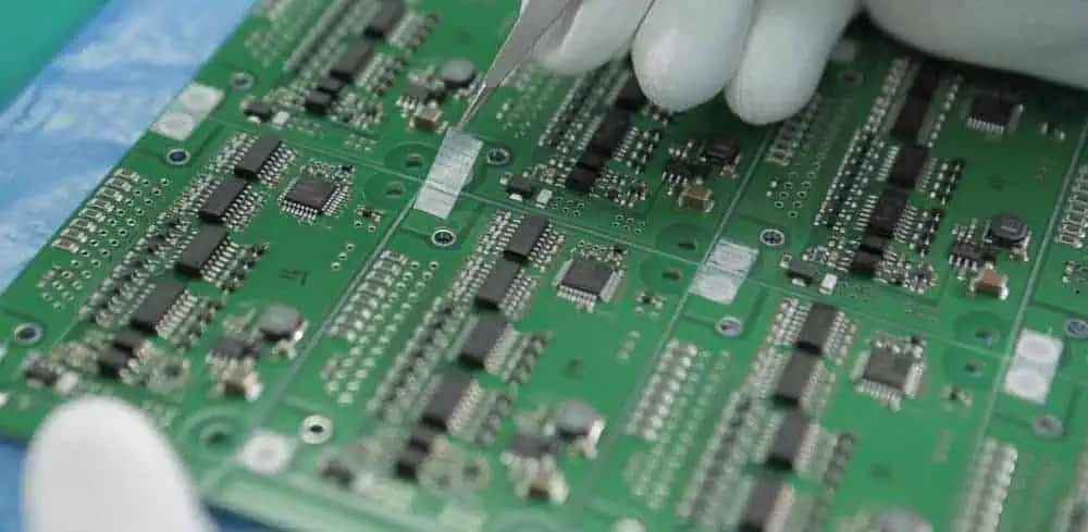
Modules employed in the process

Several different process modules may be present in a microelectronics manufacturing process. In addition, these modules may be integrated or separated in various ways within the semiconductor fabrication system.

A typical semiconductor manufacturing system may include several process modules, each of which has a unique function. For example, these modules may consist of a multi-wafer process module, a single-wafer process module, a wide-entry process module, or a dual-entry process module. In addition, each process module may contain a processing tool, such as a lithography tool or a tool for plasma processing.

A single-wafer process module may have an entry shaped to fit one wafer. This entry may also be wider to accommodate multiple wafer passage paths. This entry may also include an isolation valve. This valve will provide a vacuum seal when closed. This valve may be employed to control the pressure, fluid level, or flow of gases.

DT vision for semiconductor manufacturing

microelectronics fabrication process flow

Despite the flurry of press releases from various vendors touting the latest and greatest, a fab is a fab, and the talent competition is stiff. Aside from the usual suspects like IBM and Intel, newcomers are vying for top-dog status. Applied Materials is among them. A recent survey of senior executives revealed that the company’s top-line revenue was down 9% compared to the previous year. But it isn’t all bad news. Part of the reason is a supply chain diversifying beyond the usual suspects. The key to success is identifying and leveraging these emerging market opportunities.

While the company hasn’t disclosed any specifics, the company mentioned above would likely be among the first to make the grade. It is a safe bet that other fabs will follow suit. If the competition continues to play by the rules, the industry can look forward to an even brighter future. Certainly, a large part of this success will come from improved supply chain and manufacturing efficiency.

Roll-to-roll

Essentially, a roll-to-roll microelectronics manufacturing process is a method for creating semiconductor devices on a flexible substrate. The process is essential in various industries, including display components, energy, medical devices, and metal fabrication. It has a high throughput capacity, which allows for the mass production of finished materials. It can also help to maintain technological superiority and capabilities developed.

The roll-to-roll process has become increasingly popular over the last two decades. Among the most successful commercial applications are display components and optics.

A roll-to-roll microelectronics manufacturing process is a series of processes that produce semiconductor devices on a flexible substrate. The process involves winding material over rollers, coating it with additive materials, and then applying it to a flexible substrate.

e-manufacturing in a semiconductor and microelectronics environment

Across the world, 100 billion integrated circuits are helpful every day. These chips are at the heart of our computers, gaming consoles, televisions, smartphones, and other electronic devices. Without semiconductors, we would not have televisions, smartphones, or advanced medical diagnostic equipment. In addition, these devices enable advances in computing, communications, transportation, clean energy, and healthcare.

With the increasingly competitive environment, the industry has been able to produce smaller, faster, and more reliable electronic devices. Microelectronics also makes it possible for devices to be less expensive. The industry is also attempting to reduce time to market and improve microelectronics manufacturing processes.

Evolution

The semiconductor and microelectronics industry is undergoing a fourth industrial revolution. It combines physical and digital technologies, including artificial intelligence, robotics, and bioengineering. The fourth industrial revolution includes the internet of things (IoT), augmented and virtual reality (AR/VR), and embedded digital computing. This fourth industrial revolution is changing the way we live and work.

The National Institute of Standards and Technology (NIST) is the only national laboratory dedicated to measurement science. It came up with a report that specifies seven premeditated “grand challenges” in modeling, simulation, and measurement. These challenges will be vital to semiconductor manufacturing.

What Products Use Microelectronics in the semiconductor industry

FULL PCB MANUFACTURING Quote

During the past 20 years, microelectronics has been the dominant force in the electronics industry. However, as it grows, many companies are facing the challenge of microfabrication for the first time. This trend will continue.

The semiconductor industry has an enormous diversity of products and processes. The demand for smaller, cheaper devices continues to grow. It has also led to serious design problems. The trend is likely to accelerate in the coming years.

The national semiconductor technology center has been working with the industry for decades. This collaboration includes intense X-ray sources, sensitive particle detectors, sophisticated microscopes, and microelectronic devices. This will allow scientists to plan for improvements in the microelectronics industry.

These advancements will be critical to protecting against cyberattacks. They will also enable researchers to use devices closer to stack separately manufactured components. This will reduce the size of lab equipment and provide scientists with devices that are more energy efficient.

The Internet of Things is also growing quickly. We estimate the IoT market will be worth hundreds of billions of dollars within a few years. This market will include wearables, home security systems, personal computers, electronic gaming hardware, and telephone answering machines.

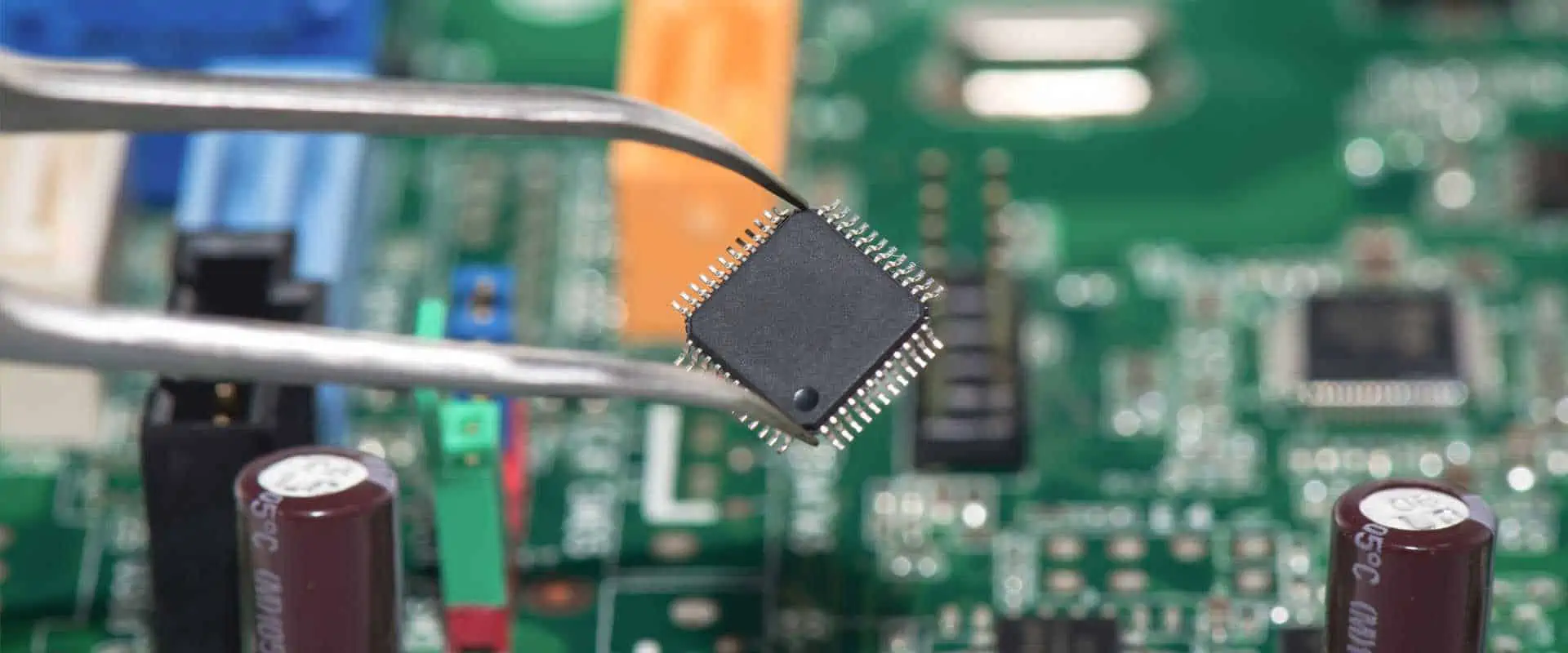
How Are Microelectronics Made?

Understanding how to make microelectronics is vital to understanding how computers work. However, there are numerous types of semiconductors, so it cannot be very clear to determine which ones you need to know. Nevertheless, here are some things you should know about semiconductors.

Integrated circuits

Integrated circuits are the main building blocks of modern electronic devices. They create them by combining small electronic components, such as resistors, transistors, capacitors, and wires.

An integrated circuit can perform operations similar to large discrete electronic circuits but is 1000 times smaller. It also requires less power, which helps to reduce the size and weight of electronic appliances. In addition, manufacturers can pack many circuits into an IC package.

Analog circuits

Unlike digital systems, analog circuits are less automated and require more skill. Analog circuits may be simple, such as two resistors combining to make a voltage divider, or complex, such as a high-fidelity audio amplifier. Analog circuits may also employ microprocessor techniques.

In general, digital circuits are more efficient and accurate than analog circuits. However, implementing an analog circuit can be more expensive and difficult.
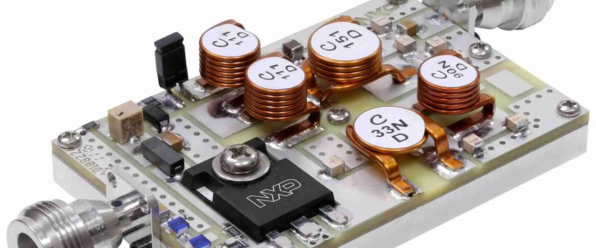
Semiconductors

Those who have watched TV or used computers know that semiconductors are essential to our lives. They enable us to power and handle electrical currents and store information. They also play a vital role in our transportation, military systems, and healthcare. In addition, without them, we wouldn’t be able to use smartphones, watches, and many other popular electronics.

Silicon is the most common semiconductor material used in heterogeneous integration. It is a chemical element found in natural rocks, soil, and water. It has a crystalline structure and is a relatively strong material.

Dry etch process

The dry etch process is more accurate than wet etching and offers a higher etch rate. It also uses less expensive chemicals and equipment. In addition, it has more control over the etch process and can be performed remotely or in a vacuum chamber. As a result, the process is often helpful in semiconductor manufacturing, display production, and micromachining.

The dry etch process involves the conversion of a gas into plasma in a vacuum chamber. The plasma is a mixture of ions, radicals, and gases. The plasma is ideal for etching metals and non-metals. It can also help to maintain technological superiority and capabilities developed.

Diffusion

Microelectronics are key components in heterogeneous integration, whether it’s a microcontroller, NAND flash memory, or DRAM. As a result, they have a significant role in enabling revolutionary changes in global commerce. In addition, microelectronics have enabled various breakthroughs in science, technology, and economics.

Making microelectronics is a complex process combining chemical processing steps and several photolithographic steps. Traditionally, doping transistor sources help to maintain technological superiority. However, more advanced processing steps are necessary for the increasingly competitive environment.

The most basic diffusion process is similar to that of a charge carrier. First, impurity atoms enter the semiconductor substrate through chemical vapor sources and then activated by annealing.

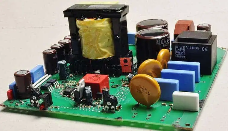
Examples of Microelectronics

During the last fifty years, microelectronics has had a significant impact on the way our world operates. Computers, calculators, televisions, and fax machines are a few ubiquitous devices we have grown accustomed to. Microelectronics is a branch of engineering that focuses on manufacturing small electronic components.

Microelectronics is a field that is constantly developing and expanding. Many large universities have begun research into the various applications of microelectronics. The focus of most research is on making the components smaller. In the future, nanotechnology will manufacture smaller, more energy-efficient, and data-nimble microelectronics. This will allow researchers to analyze more data faster and support ever-stronger supercomputing capabilities.

How Supply Chain Disruptions Threaten Semiconductor Manufacturing

micro manufacturing techniques

Several factors have created a supply chain crisis for semiconductor manufacturing. These include geopolitical tensions and the global economy. In addition, manufacturers face a shortage of key raw materials. Nevertheless, the semiconductor supply chain creates a huge value, generating between $45 billion and $125 billion in annual cost savings.

In response, the Biden administration has been working to improve US manufacturing. One of its efforts is the Made in America initiative. However, while the Biden administration has done its part to boost US manufacturing, supply chain disruptions threaten the fabrication process. Its impact can range from short-term operational disruptions to longer-term economic damage. Therefore, it will be necessary for companies to develop supply chain resiliency to mitigate the severity of supply chain surprises.

The semiconductor supply chain is an integrated, complex system requiring resiliency to avoid disruption. This is particularly important because computer chips are helpful in many electronic devices.

Chip shortage has hit the automotive industry hard. It has reduced the number of trucks that Daimler and Volkswagen have to operate by five digits over the past two years. It has also delayed the launch of a number of consumer electronics merchandise. And the chip shortage has affected companies’ ability of onboarding new workers.

The chip shortage will only worsen if new supply chain bottlenecks arise. For example, the auto industry has already canceled orders, anticipating lower demand. In the meantime, some contractors seek job extensions because of material shortages.

How Microelectronics Will Transform Future Technological Performance

Whether you are interested in microelectronics or are a scientist or engineer, there is a great deal to be learned about how technology will transform how we interact with the world around us.

Moore’s Law

Whether or not Moore’s Law in microelectronics will continue to transform future technological performance is still a debate among industry experts. However, several observers have speculated that the Law will eventually end.

Moore’s Law specifies that transistor number in a given dense integrated circuit doubles after every two years. It has been a key benchmark in microelectronics for decades. Its influence has also extended to other digital technology measures, such as memory capacity and sensor improvements.

Eroom’s Law

Developed by researchers at the University of Nevada, Eroom’s Law of microelectronics is a surprisingly short term in a competitive industry. The gizmo is a small microprocessor paired with a microchip capable of storing massive amounts of information is a feat of engineering and computer science. The best part is that it is feasible and affordable to the average Joe and Jane. The resulting microchips are rising as smartphones and mobile devices grow in popularity. Likewise, the number of companies engaged in microelectronics has grown significantly. And the quality of these chips is only getting better. Naturally, this has a knock-on effect on productivity and quality of work.

Swanson’s Law

Even though we have a solar industry that is growing at a rapid pace, we have yet to see the sunshine on par with coal, gas, and nuclear power. Gas-fired power stations produce a fifth of the world’s electricity. So it seems like a given that fossil fuel-powered electricity will not be going anywhere soon.

Swanson’s Law, based on those mentioned earlier mentioned, is a set of consistent observations about the photovoltaic power industry. The most impressive observation is that the cost of a photovoltaic cell is on the decline for every 100% increase in sales volume.

The Law also has a more subdued cousin. Unlike the sun, the cost of building a coal or natural gas-powered power plant in the US is a hefty three dollars per watt. Fracking allows us to extract natural gas from shale at a fraction of the price.

Threadwork

Across the entire electronic system life cycle, energy efficiency, climate protection, and sustainability are key considerations. Microelectronics is a critical driver in addressing these needs. Research and development efforts include advanced materials, EDA design tools, and core IP.

These microelectronics research and development efforts will advance the fabrication technologies and materials that will enable the next generation of computing architectures. They will also support the research and development of microelectronics critical to the missions of the national semiconductor technology center.

Microelectronics can help create a new kind of computing architecture, which combines different levels of computing with different degrees of speed, memory, and storage. The technology will also provide increased functionality for future computing needs.

Types of Wire Connections in Electronic Cable Assemblies

Electronic Cable Assemblies

Choosing the right wire connection type for your cable assemblies can be an essential factor in ensuring the proper electrical connection of the circuit. The types of wire connections available include Insulation-displacement connectors, Terminal blocks, and Screw connections.

Insulation-displacement connectors

Generally, insulation displacement connectors are electrical connectors used to form an electrical connection between a conductive core and a PCB. Moreover, this connector is helpful for various applications, including telecommunications and medical equipment. Insulation displacement connectors are available in various types and configurations. The benefits of this type of connector include low contact resistance, high contact density, and high normal force. These connectors are also RoHS compliant.

An IDC connector comprises an insulative housing with a top surface and a series of passageways. The passageways can allow external network cables to enter into the connector. The connector also has a pair of electrical contacts. The electrical contacts go in phoenix contact receiving slots defined by the front and rear side surfaces.

Wire-to-board connectors

Cable Assemblies

During the process of manufacturing electronic cable assemblies, there are several types of connectors available. One of the common types is the wire-to-board connector. These are rectangular devices that contain a male and a female part. These connectors connect wires or ribbon cables to a printed circuit board. As a result, these connectors can differ in orientation, pitch, and construction materials.

Wire-to-board connectors are commonly helpful in various automotive, communication, lighting, and industrial industries. These connectors are efficient and cost-effective and provide long-term reliability. Some connectors even have locking mechanisms. These locking mechanisms include friction lock, quick disconnect, and full lock. These locking mechanisms ensure that the wire stays securely in the socket.

Several wire-to-board connector types are available, including surface mount and through-hole types. The surface mount version of the connectors uses pins soldered to the pads on the PCB. The through-hole version uses pins inserted through the board.

Wire-to-wire connectors

Whether used in industrial, lighting, telecommunications, and automotive applications, wire-to-wire connectors are versatile and efficient. They are also a cost-effective way to establish an electrical connection.

The housing of a wire-to-wire connector stabilizes the connection and protects the electrical contacts from environmental hazards. Several housing geometries are available, including surface-mount, surface-mount, and over-molded. In addition, these connectors are available with different power contacts, receptacles, and locking designs.

The size of the wire that will connect to the connector is another factor to consider. Also, thinner wires are less likely to carry current. The wire’s thickness also affects the wire’s electrical resistance over a given length. Depending on the application, it may also affect the strength of the connector.

The size and conductivity of the wires used in the connectors are also important. The conductors of the connector consist of metal or plastic. We affix the conductors affixed on the connector’s male and female sides. Depending on the connector type, the conductors may also consist of silicon or carbon.

Terminal blocks

Various types of wire connections are helpful in electronic cable assemblies. These connections include feed-through, screw, pre crimped leads, edge, and connectors. Each has its advantages and disadvantages. Therefore, knowing each type’s basic principles and specifications is essential before selecting.

The term terminal block is also commonly used for a connector type. These connectors help secure wires and ensure a secure and fast connection. Terminal blocks are available in various types, sizes, and configurations. In addition, they are usually modular, which allows them to mount on printed circuit boards (PCBs) and DIN rail. We can install them using a screwdriver.

The most common type of terminal block is a feed-through block. The connectors are metal and grounded to the panel. The connectors can be reversible, allowing different colors of the same module type.

Screw connections

Several types of screw connections are available. They are used in electronics to provide an electrically secure connection. We can adapt these connections to support various devices. They are commonly used in switchgear and building wiring devices. The advantage of using screw connections is that we can reuse them in the field. They are also relatively inexpensive.

The most common type of screw connection is a hand-screw connection. This connection has a secure fit and is easy to install. It also provides a good grip.

Another common type of screw connection is a clamping plate screw connection. This connection uses a sleeve of metal to hold the wire. The wire can be inserted directly into the sleeve or wrapped around the screw head. It is essential to use the proper wrapping method to prevent the conductors from being forced outwards by the screw.

Choosing HDMI Cables

FULL PCB MANUFACTURING Quote

Choosing the right HDMI cables is essential for a variety of reasons. They can connect your TV, BluRay player, or PlayStation to your computer. They can also be helpful in gaming, HDR content, and other useful applications. However, not all HDMI cables are created equal. The most important thing to look for is the speed of the cable.

There are four-speed categories for HDMI cables. Class 1, Class 2, Class 3, and Ultra High Speed. Each of these has a different maximum data rate. A high-speed HDMI cable is essential for streaming 4K Ultra HD video.

The HDMI Forum defines the standards for HDMI cables. These depend on the features the cable supports. For example, a high-speed HDMI cable generally supports more data than a low-speed HDMI cable. This is because it has a faster transfer rate and can handle higher data rates.

HDMI cables can be active or passive. Active HDMI cables have a built-in signal amplifier that transmits data from the source to the display. Active HDMI cables have a higher refresh rate, which produces smoother images.

HDMI cables are also available in various colors. Black network cables are the most common, but some people prefer to purchase network cables with discreet colors. The color of the cable may not matter much, but it is a good idea to choose a cable with good insulation.

Some of the newer HDMI cables may have a gold-plated connector. Gold-plated connectors are supposed to be more resistant to oxidation. This may make a slight difference with an analog signal. However, a digital signal is not affected by gold-plated connectors.

Choosing Cable Assembly Companies

Choosing a cable assembly company requires several factors. These factors include experience, cost, quality of workmanship, and more.

Cable assemblies help to connect a variety of systems, equipment, and devices. They are helpful in many industries, including consumer electronics, business/office, automation, manufacturing, military/aerospace, telecom, and transportation.

The automotive industry is one of the largest users of cable assemblies. In addition, with an increase in EV sales, the market for cable assemblies will grow significantly.

Koch Industries is an authorized distributor in the cable assembly market. The company has been building world-class products for decades.

Carl Stahl Sava Industries offers custom-engineered cable assemblies. The company also offers wire, precision miniature cables, pre crimped leads, assembly fittings, push-pull control assemblies, and prototype assembly kits.

Bergen Cable Technology manufactures tin over zinc cables. The company also provides vacuum packaging and flash-cutting services.

Amphenol DC Electronics is a leading designer and manufacturer of electrical connectors. Its product portfolio includes fiber optic connectors, minimum order quantity, electronic connectors, and interconnect systems.

TE connectivity is one of the leading manufacturers and sells consumer electronics, military equipment, and aerospace parts. It also offers sales, design, and manufacturing services.

TE connectivity is a cable assembly company that manufactures custom cable assemblies, wire harnesses, shrink tubing, and insulation. This company is an essential part of any electronic system. Additionally, TE connectivity offers innovative consumer products and technologically advanced technology. They consolidate potentially dangerous electrical wiring, preventing it from getting tangled and disrupting signals. As a result, TE connectivity has earned recognition from clients worldwide.

Functions and Types of Motor Control PCB Board

Motor Control PCB

Motor control systems are crucial to the protection and functioning of industrial equipment usually powered by electric motors. Basic motor control technologies are widely integrated in devices. Also, motors are crucial components in several electrical engineering projects. It is important to have a good understanding of motor operation and motor control. Also, you should know how motor control impacts engineering projects.

What are Motor Control Devices?

Motor control devices govern the functioning of an electric motor in a controlled manner. Also, these devices can help to start or stop a motor fixed to a machine. Motor control devices are also known as motor controllers. Also, they can be controlled automatically or manually. Motor controllers control the operation of an electric motor.

Also, motor controllers can regulate or limit the torque of an artificial system and protect against faults and overloads. In artificial lift applications, motor controllers are devices integrated with VFDs or switchboards to regulate the prime moverโ€˜s operation. Also, some motor control devices include additional features like data logging and data collection.

Motor controllers often use automatic or manual methods to control speed, stop, start, and reverse a motor. Also, they are often used with both AC and DC motors. Controllers can link the motor to the supply of electrical power. Furthermore, they may protect the motor from overload. Motor control devices can check the field circuit of the motor or identify issues like incorrect phase sequence, low voltage supply, and incorrect polarity.

Some motor control devices restrict the inrush starting current and as such, enable the motor to increase itself and link mechanical load slower than direct connection.

Functions of Motor Control

Motor Control board

Motor control systems perform some basic functions. We have mentioned some of their functions earlier.  We will be discussing these basic functions extensively in this section.

Starting

One of the primary functions of a motor control system is starting the motor. Motor controllers can employ several methods, based on the circuitโ€™s requirement. However, the across the-line starting is the simplest method. This method involves linking the motor directly to the power line. In some cases, the motor may need to start at a low speed and increase to full speed. Also, this is usually known as ramping.

Stopping

This is another important function of a motor control system. Also, the easiest method to stop a motor is to disconnect it from the power line. However, the motor may need to stop more quickly in some cases.

Motor and circuit protection

Motor control offers protection for the motor and the circuit components. Circuit breakers and fuses are usually integrated for circuit protection. Also, overload relays help to protect the motor.

Jogging  and inching

These are methods motor control employs to move a motor with short power. Jogging and inching are usually performed to move a load or motor in desired position. However, there is a slight difference between the two. You can accomplish jogging by momentarily linking the motor to full line voltage. On the other hand, you can achieve inching by linking the motor to reduce voltage.

Types of Motor Control Devices

Motor controllers can be either controlled manually or automatically. Also, you can control them in a remote manner. Motor control devices offer protection against several degrees of electrical faults and overloads. However, these controls are in different categories based on the type of motor they can operate.

Reduced voltage starters

For this type, two or more starters start a motor in low voltage conditions. Lower voltage is at the motor terminals via a series of autotransformer and inductance. Also, this helps to minimize the inrush electric current and the starting torque. The starter will send full voltage to the motor terminals immediately the motor gets to a particular portion of its top-load speed.

Intelligent controllers

These motor control devices integrate advanced microprocessors for regulating electronic devicesโ€™ power used in an electric motor. Also, these motor controllers regulate the load on a motor and ensure he torque matches with the recorded load.

Motor starters

To start small motors, plug the electric switch in the receptacle and then switch on the power button. Larger motors require contractors or motor starters. Moto starters are switching units that power an electric motor. After it has been powered, there is a connection between the direct on-line starters and motor terminals.

Servo controllers

These motor control devices have unique features such as fast acceleration rate, precise speed control, and precise closed-loop positional control. Also, these control devices integrate position feedback to close the control loop.

Adjustable-speed drives

Adjustable-speed drives are unified combination of devices that allow operators to drive and also adjust a mechanical loadโ€™s operating speed. Such drives include power converter, speed controller, and various auxiliary devices and equipment. An electrical adjustable-speed drive features a speed controller and an electric motor.

Types of Motor Controllers and Drives

FULL PCB MANUFACTURING Quote

Alternating Current (AC)

AC motor controllers and drives can adjust the frequency power of the motor thereby, modifying the input power to motors. This helps to regulate the torque and output speed. You need to consider key specifications such as power rating, drive operating mode, loop system classification, and motor type. Also, AC motor controllers are primarily integrated in process applications to regulate the speed of blowers, pumps, etc.

Furthermore, they are known as AC inverters or variable speed drivers. The controller supplies the driveโ€™s control signals. AC motors may not have much speed response to adjust terminal voltage. Therefore, controllers for AC adjust rotor circuit resistance.  AC motor drives regulate the speeds of motors that drive fans, pumps, and more

Direct Current (DC)

DC motor controllers and drives adjust the alternating current source to modify the input power. Key specifications here include drive operating mode, communication interface, intended application, and motor type. Also, these controllers and drives help in regulating torques and motor speeds for electric vehicles, machine tools, and more.  The controllers in direct current motors may adjust the voltage use for the motor.

DC motor drives regulate permanent magnet DC motors operating from AC sources. Also, these drives feature low-speed torque, which makes them ideal for cranes, winches, and more

Stepper

Steppers are electronic devices that change the input power by simply adjusting the source of alternating current to a โ€œsteppedโ€ or pulsed current output. Stepper motor controllers and drives are mainly integrated in motion control applications in construction and manufacturing environment. Also, they are widely used in controlling torques, motor speeds, and position.

These motor controllers and drives are commonly used in applications like robotics, machine tools, and other types of machinery.

Considerations in Selecting Motor Controllers and Drives

You need to know the motor type when selecting motor controllers and drives. If you are deciding to use AC or DC drives, you will need to consider some factors. For instance, DC motor drives feature good low-speed torque and as a result, this makes them an ideal option for cranes and winches. Also, these drives are suitable in applications where you need to lift loads without a โ€œrunning start.โ€

On the other hand, AC motor drives are ideal for applications that need to regulate the speeds of motors. Therefore, they are widely used in fans and pumps. AC motor drives increase efficiency by setting the speed of fan and pump to match requirements.

The nature of application is another consideration when choosing between AC drives and DC drives. AC drives are specially designed for constant or variable speed applications.

Types of Control Systems in Motor Controllers

There are three types of control methods in motor control systems. These are automatic, manual, and semiautomatic.

Automatic control

In automatic control, some actions initiate automatically. Once the operator sets the control conditions, the motor control system will operate on its own. The cooling and heating system in several homes is a good example of automatic control system. Also, the control circuit comprises sensing devices that shut the system automatically when there is an unsafe condition like excessive current.Automatic control integrate current sensors or internal timers to increase the motor.

Manual control

In manual controls, the operator must initiate any change. Also, manual controllers are usually simple devices that directly link the motor to the line. However, this type of control may not protect overload or release low-voltage. You can accomplish manual control by connecting a switch in series.

Semiautomatic control

This involves the use of pressure switches, push buttons, and other sensing devices to regulate the operation of a magnetic starter or contactor. Also, the starter links the motor to the line and other pilot devices to regulate the coil of the starter.

Motor Control Components

Motor Controller board

As explained earlier, there are various types of motor controls. Each of these motor controls integrates different mechanisms. Therefore, they are different types of motor control components. It is crucial to know the function of these components.

Motor circuit breaker

This component protects against short circuits and overloads. It works in a similar way with an ordinary circuit breaker. When short circuit or overload occurs, the device switches off the motor. You can fit in auxiliary contacts to offer a tripping feedback details to a pilot light indication. Furthermore, you can use motor circuit breakers with contractors for the loadโ€™s control.

Thermal overload relay

Thermal overload relay offers protection against current overloads that may result in overheat and service disruption. Also, this relay uses bimetallic strips. These strips heat up when overcurrent occurs.

Contractor

This is an electro-mechanical devices that switch off or switch on motor load. To switch on this contractor, voltage has to be applied across the coil terminals. A contractor works better than relay as it is ideal for higher power rating. Also, a contractor isnโ€™t only used for interrupting short circuits only. It serves other purposes.

Mini contractors

In reality, mini contractors function like contractors. However, they are much smaller. This offers reliability and efficiency where space saving is necessary.

Motor control accessories

These are peripheral devices attached with a motor to ensure its smooth operation. There are various motor control accessories based on the motor need.

What are DC Motors?

Motor Controller PCBA

DC motors convert electrical energy into mechanical energy. They operate on DC power-non-sinusoidal. Also, DC motors include basic parts such as stator, rotor, field magnets, and commutator. These motors function based on a principle of electromagnetism introduced by Faraday. This principle states that when you place current-carrying conductor present in the magnetic field, it feels and experiences a specific force.

DC motors are available in different types based on their construction. The brushed or brushless, series, and permanent magnet, are the most common types of DC motors.

Types of DC Motors

Brushed and brushless motors

Brushed DC motors use carbon brushes to deliver current from the armature. These brushes are close to the commutator. The brushless DC motors donโ€™t have graphite or carbon brushes. Also, these DC motors  comprise permanent magnets. Furthermore, brushless DC motors integrate electronic circuits to regulate the direction of speed and rotation.

Series-wound DC motors

Series motors have their field windings and stator windings usually connected in series. Also, the field currents and armature currents are always equal.

Permanent magnet DC motors

These DC motors comprises a rotor with two opposing permanent magnets. When you pass DC, these magnets deliver a magnetic field flux. This makes the rotor to spin in ant-clockwise or clockwise direction. One advantage of this type of DC motor is that it can function at synchronous speed.

Shunt DC motors

Shunt DC motors comprises field windings and armature which are usually connected in parallel. Also, both windings get the same voltage supply due to the parallel connection. Shunt DC motor can feature excellent speed regulation. However, they donโ€™t have high starting torque.

What RayMing Offers You

RayMing has the experience and sophisticated manufacturing facilities to help you design your motor control project. Regardless of your motor control needs, we offer you the best. We work with a team of experienced engineers devoted to offering the best solution to your motor controller needs.

Also, our motor control devices are ideal for use in different applications. We would like to provide the best motor controllers for you.  Furthermore, we offer support services such as assembly and technical support.

What are the Components of PCB?

PCB Embedded Components

PCB components are the parts making up a Printed Circuit Board (PCB). Without these parts, the circuit board might not be fully optimized to attain all the potentials. In this article, we explain what these components have to contribute to the PCB.

What is a PCB?

The full name is Printed Circuit Board. It is a centralized or mono-circuit-board โ€œwarehouseโ€ designed to accommodate most of the components used in consumer electronics. PCBs are in high-demand because of the less complicated process they bring when designing modern electronics.

Before the introduction, consumer electronics were mainly designed with different components and wires all scattered inside the product. But with the introduction and the continuous innovations in PCB designs, these parts can now be housed or placed inside one place โ€“ the circuit board.

Wikipedia defined PCB as one of the core engineering concepts and processes that allow for the โ€œconnection of electronic components to one another in a controlled manner.โ€

Today, PCBs can be manufactured with different process technologies, such as the Surface Mount Technology (SMT) and the Through Hole Technology (THT). PCBs have also been optimized to work with and accept the integration of different parts, including Integrated Circuits (ICs).

How Do You Identify PCB Components?

If a Printed Circuit Board (PCB) is placed in front of you, how are you going to identify it? What are some of the clues to look out for when checking for the components on the board?

The first thing to have in mind is that identifying the electronic components might be difficult, but luckily, there are some clues to figure it all out.

Thus, below is a table showing some of the designators โ€“ the letters or alphabets likely to be printed on the PCBโ€™s surface. Beside each of those designators is the full meaning. So, the next time you see the letters or alphabets marked on the PCB, you know what they mean.

DesignatorsFull Name
ATTAttenuator
BTBattery
CBCircuit Breaker
BRBridge Rectifier
DDiode
CCapacitor
GOscillator
DCDirectional Coupler
FFuse
ICIntegrated Circuit
JJack or Jumper
LInductor
KContractor/Relay
PPlug
LEDLight Emitting Diode
PSPower Supply
LSLoudspeaker
MOVMetal Oxide Varistor
SWSwitch
QTransistor
TBTerminal Block
POTPotentiometer
TPTest Point
RResistor
TRTransistor
TTransformer
XTransducer
TCThermocouple
UIntegrated Circuit
Z/ZDZener Diode
VRVariable Resistor
XTALCrystal

Understand the General Classifications of the Components

FULL PCB MANUFACTURING Quote

One of the best ways of identifying the components mounted or placed on a Printed Circuit Board (PCB) is by understanding the general classifications.

Generally, the components are classified into the mechanical and electrical components. Each of the two works in different ways and understanding these processes will help you figure out the PCB components faster.

How the Electrical Components Work

As the name signifies, these are the components that rely on electrical energy. They are usually placed on the PCB using either of the Surface Mount Technology (SMT) or Through Hole Technology (THT). Both are process technologies used in the design and configuration of Printed Circuit Boards (PCBs).

The electrical components are either soldered directly to the PCB or passed into the circuit board, using wires.

Mechanical Components

These types of PCB components use a โ€œmechanizedโ€ process, which has to do with the type of metal used in them. Typically, the mechanical PCB components are made of aluminum, but there are a couple of others made from steel, copper and bronze.

The difference between the mechanical and the electrical components is that unlike the electrical that provide electrical functions, the mechanical components donโ€™t. Instead, the primary function of mechanical components is to provide additional or secondary support to the PCB.

How to Identify the Through Hole Components

The Through Hole Technology (THT) is one of the process technologies used to manufacture Printed Circuit Boards (PCBs).

The components placed on the board via this technology are typically large-sized and have long leads. These leads have openings for holes to be passed through them to enable the placement on the PCB.

So, if you see a PCB component that has is attached to a pad with solder, it is likely to be a THT component.

While it is easy to identify a Through Hole Technology (THT) component, it is not always the case with a Surface Mount Technology (SMT) component.

What are SMT Components?

These are the PCB components โ€œmountedโ€ or โ€œplaced atopโ€ the Printed Circuit Board (PCB). Unlike the THT components, they do not use holes for the mounting process.

While these components can be identified because of the shorter leads and absence of holes, there are a couple of other important factors to have in mind.

Below are some of them:

  • These components have shorter leads.
  • They do not have holes.
  • These components rely on soldering of the surfaces to the coppers pads atop the Printed Circuit Board (PCB).

The Broader Division of Electrical PCB Components

Printed Circuit Boards (PCBs), which are classified under the electrical components, are furthered divided into the passive and the active electrical components.

Remember that the electrical PCB components are the circuit board parts, which are acting as secondary materials. Thus, all they do most of the time is to provide electrical connection of the components/parts to the PCB, either in the form of direct soldering or through wired connections.

Now, most of the electronic power configurations of a PCB are delivered via these electrical components. These parts are also further broken down into the passive and the active components, depending on how they transmit the electrical signal.

The Passive Electrical Components

Being โ€œpassiveโ€ implies that these parts do not directly transfer electrical energy or control the flow or passage of energy through them. Most of the passive electrical components have two (2) leads.

While the easiest way to identify a passive electrical component is via the silk screen printing atop the Printed Circuit Board (PCB), there can be other ways to identify it.

Below are some of the popular linear passive components you can find as a way of identifying the passive electrical parts on a PCB.

1. Capacitors (C)

Capacitors are one of the popular through hole components. They are identified with the Capacitance Value or โ€œC.โ€ So, if you see a component or circuit part marked as โ€œCโ€ or starting the alphabet โ€œC,โ€ there is a chance that it is a capacitor.

Now that we know how to identify a capacitor, let us understand how it works. It is used to store energy in an โ€œelectric fieldโ€ and is usually rated in Farads. The rating can either be written in Millifarads (mF) or in Microfarads (ยตF).

2. Fuse (F)

Denoted by the alphabet โ€œF,โ€ the Fuse is one of the most outstanding components used in PCB manufacturing. It is also easy-to-identify. You can recognize it because of the typical glass body, through which a fuse wire can be seen. The Fuse also has metal caps, which protect both ends of the fuse.

Note that it is common for the fuse to have the above characteristics if it is a through hole component. However, if you are working with a surface mount fuse, the properties typically include a semi-clear tube axial leaded slightly above the fuseโ€™s surface.

3. Resistors

As the name signifies, the resistors are used for โ€œresistanceโ€ โ€“ but the question is, what are the resistors resisting?

Resistors are one of the passive electrical PCB components, because they are designed in the form of passive two-terminal components. At the core of the operation is the โ€œresistance,โ€ โ€œrestrictionโ€ or โ€œpreventionโ€ of electric currents to pass through them.

Resistors can also be used to โ€œwedgeโ€ or stop the passage of the voltage in each of the connected components.

Since the function of a resistor is โ€œcurrent or voltage restriction,โ€ how then can one tell if it is a resistor or not? We have an idea on how to identify it faster.

First, check if the component has a longish body or structure and if green or blue bands of different colors are imprinted on it. If it does, it means that it is a resistor, because those varying colors highlight the important elements, such as the tolerance and value.

The second way to identify a resistor is by checking the alphabets. Resistors typically start with the alphabet โ€œR.โ€

The third and most difficult way to identify this component is by considering the body size. Although the ideal size is longish, there are some that could be smaller, especially if these resistors are manufactured with the Surface Mount Technology (SMT). For this type of resistors, the body size is smaller and might not any marking or color to signify them. But if you are able to pick out the alphabet โ€œR,โ€ it will be a lot easier for you.

4. Connectors

These are also one of the passive PCB components. Ideally, connectors are used for โ€œconnecting,โ€ โ€œattachingโ€ or โ€œintegratingโ€ multiple components. The ideal design is the attachment of the circuit board to a larger component. It can also be used to connect the attach one circuit board to another.

The simplest way to identify a connector in a PCB is to look out for the initial alphabet โ€œK.โ€ It is also possible to make the identification by:

  • They can integrate with jumpers. In this instance, the jumper wires will have connector pins at each end of the wires.
  • The sizes of the connectors also vary. They can either be slim or large. If they are slim, it means that the connectors are optimized for the flat cables to connect to them. But, if they are larger, it implies that other connectors can connect or be plugged into them.

5. Inductors

Inductors are easily denoted by the alphabet โ€œL.โ€ They are also a two-terminal component, primarily used for storing the electric power or store energy in a magnetic field. The energy storage happens when electric current passes through the inductors.

Note that the inductors are easily identified with the initial alphabet โ€œL,โ€ but there could be some other technicalities making it impossible to identify the component. Due to these, you want to pay more attention to the values or markings imprinted on it.

Inductors can be identified with any of the following markings or values:

  • H
  • ยตH
  • mH

6. Battery

We will not complete the list of electronic components mounted or โ€œpassed throughโ€ a circuit board without mentioning the battery.

The commonest way to identify a battery is to look out for the alphabets โ€œBTโ€ on the body. The battery is one of the passive electrical components and is used for storing energy and providing backup power for the Printed Circuit Board (PCB).

Aside from the imprinting of either โ€œBTโ€ or โ€œBโ€ on the body, the battery can also be identified with any of the following:

  • Check if it has either a blue or a green shrink-wrapping.
  • The shape can be in any of the following forms: coin-shaped, rectangular-shaped or cylindrical-shaped.

The Active PCB Components

Now that we understand some of the small electronic devices or components used in the passive states, let us look at the active ones.

The following are some of the active PCB components, all generally classified under electric current PCB component.

First, let us understand why they are called active components. They are so-called, because these are the components that help facilitate the electric signal passage in the PCB. These components are also available in both the Surface Mount and Through Hole process technologies.

Besides, you can use the active PCB components to enable electrical signal passage in different ways.

With that said, here are some of the popular active components in todayโ€™s PCB assembly process:

7. Integrated Circuits

Denoted by either the alphabet โ€œUโ€ or the alphabets โ€œIC,โ€ the Integrated Circuit is one of the easiest PCB components to identify. It has been in use for over 6 decades now, but the modern electronics spot new features, such as microcontrollers and microprocessors.

It is pertinent to mention here that the IC is the โ€œpowerhouseโ€ of the Printed Circuit Board (PCB), as the absence can hamper the boardโ€™s further configuration. It attained that status because of the following factors:

  • Integrated Circuits (ICs) hold the major โ€œbuilding blocksโ€ of a PCB. These blocks include but are not limited to oscillator, amplifier (especially the Operational Amplifier), microprocessor, memory and timer devices.
  • Because of the optimization as a microchip, the ICs help to save circuit board space.

Integrated Circuits (ICs) are also known by other names, such as Microchip, Chip and IC.

While you can identify the IC with the alphabets โ€œUโ€ or โ€œICโ€ imprinted on the silk screen next to the circuit board, it can also be identified some other way.

An alternative identification method is by checking the size of the body and the number of lads. That brings us to the different classifications of the IC. It can be broadly classified into the through-hole and the surface-mount variants.

If you are working with the through-hole IC, the identification metrics are:

  • The ICs can come either in form of dual-in-line or single-in-line packages.
  • The through-hole chips have several leads on either one side or on both the long sides.
  • You can also identify a through-hole IC because of the longish body.

On the other hand, the surface-mount Integrated Circuit (IC) offers more package options than the through-hole chips do. In addition to supporting the dual-inline and the single-inline packages, the surface-mount ICs also support the following:

  • Ball Grid Array (BGA)
  • Quad chip packaging

We want to mention that before an IC is made, it has to be processed via a wafer or wafers of semiconductor materials. Despite housing multiple components, on a standalone basis, ICs are small electronic devices, which have been โ€œunitedโ€ or โ€œintegratedโ€ in the same footprint to offer multiple functionalities at once, while saving circuit board space.

8. Diodes

Denoted by the alphabet โ€œD,โ€ Diodes are one of the PCB components you can easily identify. Note that these components typically regulate voltages, most times, doing so in a one-way model. It means that the diodes act as a one-way switch for currents or voltages in a Printed Circuit Board (PCB).

How Diodes Work

As a one-way switch for currents or voltages, diodes help to pass โ€œone current at a time.โ€ Thus, it allows currents or voltages from one direction to pass, while preventing the same coming from a different direction from passing.

Aside from the current or the voltage restriction capabilities, the diodes also help to rectify the Alternating Current (AC) into the Direct Current (DC).

Here are some clues on how to identify if the component you find on circuit boards are diodes:

  • The through-hole diodes are identified by the transparent glass cylinders, small cylindrical shapes with protruding leads, and black opaque bodies.
  • For the surface-mount diodes, they can be identified by the following: polarity marking and denoting with either the alphabets โ€œZโ€ or โ€œZDโ€ โ€“ for the Zener Diodes.

Classifications of Diodes for Easy Identification

You may have seen diodes, but you didnโ€™t know what they are. Well, there are several types of diodes and understanding these can help you in placing a hand on them when you see one.

First, you want to understand that the diodes are made of semiconductors and typically have the P-N junction. With that being said, here are some of the types of diodes:

  • Tunnel diode
  • Zener diode
  • Rectifier diode
  • Silicon-Controlled Rectifier (SCR)
  • Photodiode
  • Bridge rectifier
  • Varicap diode
  • Schottky diode
  • Constant-current diode
  • Shockley diode
  • Light-Emitting Diode (LED): The Light-Emitting Diode, also called the LED, is one of the popular diodes. It is generally known to be used to emit light. The process of emitting the light involves the use of the LED to convert the electrical energy into light.

9. Transistors

Transistors are a part of semiconductor devices. It plays an important role in the electrical connections of PCBs, especially those requiring mass production.

Transistors work by amplifying and rectifying electrical signals inside Integrated Circuits (ICs). Transistors also perform several other functions, such as:

  • Conducting and insulating electrical signals
  • Acting as amplifiers
  • Transistors also act as switches for these electrical signals

The following are some ideas on how to identify a transistor inside a Printed Circuit Board (PCB):

  • Check for the marking. Transistors typically start with the alphabet โ€œQ.โ€
  • Transistors can operate at lower voltages, even when they donโ€™t use a filament current.
  • These components are smaller in size
  • There are several variants of transistors, ranging from Field Effect Transistors (FETs), PNP Darlington Transistors, Metal-Oxide-Semiconductor Field-Effect Transistors (MOSFETs), PNP Bipolar Junction Transistors (BJTs) and N-Channel MOSFETs.

What are the 3 Types of PCB?

Product-Assembly
Product-Assembly

There are several types of Printed Circuit Boards (PCBs), but three (3) of them are outstanding. Here are the 3 and how they work:

Single-Sided PCB

Also called the single sided boards, these are the Printed Circuit Boards (PCBs) that donโ€™t use multiple conductive layers. Instead, it uses just one conductive copper layer, which is placed above the substrate.

The general specifications include:

  • The placement of one layer of the base substrate and one single, conductive layer, which make up the fiberglass and copper, respectively.
  • The single-sided boards also have the electrical components placed on one side and the conductive circuit placed on the other side.

Double-Sided Boards

The double-sided PCBs are the opposite of the single sided boards in the sense that they use one layer or conductive material (preferably copper) on both the top and bottom sides of the circuit board (the two sides of the substrate).

The double-sided PCBs can be connected on either side using either the Through-Hole Technology (THT) or Surface Mount Technology (SMT). If the through-hole is to be used, the through-hole components or the lead components must be installed into the pre-drilled holes on the Printed Circuit Board, before using a soldering iron to apply a solder mask to the pads on both sides of the circuit board.

If you are to use the surface-mount process, the process simply involves mounting the electrical connections on the circuit boardโ€™s surface.

Multi-Layer Boards

If you are looking for a PCB manufacturing process that uses several copper layers, it has to be the multi-layer PCB.

As the name suggests, it supports the use of multiple conductive layers, usually exceeding two (2).

The minimum number of supported copper layers is 3 and it can be as high as 40. The configuration process involves interconnecting the conductive layers with copper plated holes.

How are Components Connected in a PCB?

Proto Electronics highlighted some of the relevance of electronic component placement on a PCB to include:

  • Helping the electrical engineers to make an accurate positioning of the electronic components mounted or drilled into the circuit board. That way, the circuitโ€™s operation will be improved, while the signal paths will be clearer.
  • Aiding the separation of the analog components from the digital components or parts.

Then, when it comes to how electronic or electrical components are connected in the Printed Circuit Board (PCB); it all boils down to two (2) process technologies.

The first process technology is the Surface Mount Technology (SMT), which involves mounting or placing the PCB components atop the circuit board.

The second is the Through Hole Technology (THT), which allows for the components with leads to be โ€œdrilledโ€ or โ€œpassed throughโ€ the pre-drilled holes before the components are added to the circuit board.

Conclusion

We hope that you now understand most of the technicalities involved in mounting or adding PCB components to circuit boards. You also understood the different processes used to do that, how they differ and the best ways to identify some of the popular PCB components.

Finally, the Surface Mount Technology (SMT) and the Through Hole Technology (THT) may be the major processes to connecting components to Printed Circuit Boards (PCBs). However, you also want to double-check the componentโ€™s orientation/placement, positioning the components before wiring and soldering the parts into place.

TPS5420MDREP: A Buck Switching Regulator

TPS5420MDREP

We already know that a DC-to-DC converter helps in converting power or current coming directly into the corresponding value. However, for a DC-to-DC converter to work effectively, it sometimes needs to work with a DC-to-DC voltage regulator.

The reason is not far-fetched from the fact that the entire current conversion process could be fraught with some power shortchanges, which may end up halting the procedure. With the voltage regulator in place, it could be much easier to scale the current conversion process.

According to Digi-Key, a DC-to-DC voltage regulator can also be called a DC-to-DC switching regulator. It is to be used with devices or applications that require a higher stabilization of the DC input voltage.

The regulator is also greatly needed with the applications that require a transformation thereof from the input voltage to the corresponding value of the output voltage, in a different magnitude.

Introducing TPS5420MDREP as a Buck Switching Regulator

TPS5420MDREP is a buck switching regulator and from what we explained in the last paragraph, its functionality might be a bit different from what a DC-to-DC switching regulator does.

STMicroelectronics explains that a Buck Switching Regulator, also known as a buck converter or a buck regulator, is a type of DC-to-DC converter. The primary use is to provide a higher output voltage than the input voltage does.

One of the highlights of this converter is how it aids power or current โ€œstep-down.โ€ In a case where the current or voltage is excessive and could potentially harm the device, it makes sense to have something to stop that from happening.

What Makes TPS5420MDREPโ€™s Buck Switching Regulator Different?

FULL PCB MANUFACTURING Quote

If you are looking to buy any product (including a power or current converting device), one of the things to consider is the unique features. Does the product have something better to offer than its competitors offer? If so, what is the relevance of those features to how the product functions?

TPS5420MDREP is indeed, a bit different from some of the other DC-to-DC converters out there because of the following features:

1. It has a Controlled Baseline

By โ€œcontrolled baseline,โ€ the manufacturer means that there might no need to look for external components to use with the TPS5420MDREP.

The controlled baseline offers this regulator a one fabrication site, and the capabilities can also be assembled and tested on the same site.

2. TPS5420MDREP Supports Internal Compensation

Despite the fact that TPS5420MDREP uses a controlled baseline design, there is a chance that the designer may want to โ€œlook elsewhereโ€ for additional components.

It is for this purpose that the manufacturer thought it wise to add a feature to restrict that. The feature is called an internal compensation. It is attached to the TPS5420MDREPโ€™s feedback loop and the functions include:

3. It Reduces Design Complexities

The internal compensation goes a long way to โ€œsmoothen the processโ€ of configuring TPS5420MDREP. This smoothening is a part of the efforts to reduce the complexities that could come with designing or configuring the target applications.

4. Zero Support for External Components

External or additional components or parts could be required and that would mean faulting the controlled baseline for TPS5420MDREP.

In this instance, TPS5420MDREPโ€™s internal compensation feature helps to minimize the need for external parts for the converter.

5. TPS5420MDREP Offers Higher Voltage Regulator

Though the core function of a buck switching regulator is to provide a higher output voltage, that of TPS5420MDREP does it better.

Here are some of the reasons why it is so:

Higher Voltage Conversion with Resistance Balance

Converting current from a higher voltage can sometimes lead to over-voltage or under-voltage. In any of those instances, some of the voltages might be lost in the process and pose a resistance.

However, it is tackled with the balanced offered through TPS5420MDREPโ€™s high-output-current PWM converter, which integrates a low-resistance, high-side, N-Channel MOSFET.

Besides the balanced offered via the MOSFET, TPS5420MDREP also helps in tightening the voltage conversion process. This it does through the high-performance voltage error amplifier. The amplifier works by providing a โ€œtight voltage regulation accuracy under transient conditions.โ€ The provision made here helps TPS5420MDREP to work even under the โ€œtightest of conditions.โ€

TPS5420MDREP also offers the following:

Voltage Feed-Forward Circuit

The function of this circuit is to improve the deviceโ€™s transient response.

Slow-Start Circuit

This is an internally-set circuit that limits the inrush currents (the rate at which current comes into the TPS5420MDREP).

We think this is a great feature because it will help prevent TPS5420MDREP from going overboard when the current inflow is beyond the rating.

Undervoltage-Lockout Circuit

This is a dedicated circuit that first, helps to prevent the TPS5420MDREP from going below the rated voltage โ€“ which is undervoltage.

It also plays a role in ensuring that the TPS5420MDREP regulator doesnโ€™t boot or function until the undervoltage issue is tackled. It is for this reason that the undervoltage-lockout circuit prevents TPS5420MDREP from โ€œstarting upโ€ until the โ€œinput voltage reaches 5.5 V.โ€

Efficiency and Accuracy

Besides regulating the output and input voltages, TPS5420MDREP also has one other function โ€“ to ensure that the regulation is accuracy.

First, it offers a 1.5% initial accuracy via the adjustable down feature with a 1.22V. This helps the regulator to maximize the wide output voltage range.

As for the efficiency, TPS5420MDREP assures that with the 95% efficiency rating, which is enabled by the 110-mโ„ฆ Integrated MOSFET Switch.

As a way of increasing the operating capacity, TPS5420MDREP supports a wide input voltage range, which is between a minimum of 5.5 volts and a maximum of 35 volts.

TPS5420MDREP Offers System Protection

It is now possible to increase the protective measures for this buck switching regulator using the several protective features. The most outstanding is the thermal shutdown, that shuts down the system. There is also the overcurrent limiting feature that prevents the system from further operations when it exceeds the rated voltage.

Conclusion

TPS5420MDREP is a buck switching regulator with several protective features, excellent current conversion properties and a wide range of components (including the fixed 500-kHz switching frequency for small size filter) that make the entire process seamless.

Everything You Need to Know About RF Amplifier Manufacturer

RF Amplifier Manufacturer

RF Amplifiers are components or solutions commonly found in devices that use a speaker to produce sound. They also have various applications in other electronic equipment and instruments. The main purpose of this gadget is to increase or amplify the signal strength. This component is considered an audio component, but the truth is that it is not just an audio component; today, they are found everywhere around us.

You will find RF systems in TVs, public address systems, vehicle audio, and musical instruments. You will also find these RF systems in many other devices or solutions that require speakers for sound. They improve the overall sound quality of any audio equipment or musical instrument to which it is connected.

What is the Function of RF Amplifiers?

Many people have heard about RF power amplifiers used in different solutions and communications, but only a few know how these RF power amplifiers work or what these RF power amplifiers are used for. If you do not understand what RF power amplifiers are and what they are used for, then the list below provides some.

1. RF power amplifiers gain

This is necessary when the amplitude of all RF power amplifiers signal communications is small and too low to be used elsewhere in the circuit and must be increased so that the overall SNR (signal-to-noise ratio) does not degrade as the signal passes through the circuit.

2. RF buffer amplifier

This is needed when a circuit function or signal needs to maintain its shape and amplitude even as the load changes or it needs to be connected to a higher load than it normally receives. The buffer amplifier ensures that the presence of this inductor does not affect the accuracy of the ยฑ1 V signal or cause distortion.

3. RF driver amplifier

The primary function of a driver, an RF power amplifier, is to generate and deliver enough current at the operating frequency to drive a low-impedance load, such as a 50 or 75 ฮฉ coaxial cable. An RF driver can also be considered an RF power amplifier if its role is to provide power amplification (current and voltage) to drive a load such as an antenna.

Understanding RF Amplifier Specifications

These are the features and specifications to consider when choosing a general-purpose linear RF power amplifier.

โ— Frequency range

Wider is better for versatile rooms when discussing frequency range for wireless applications. Most designs of RF power amplifiers for wireless applications have a frequency range from 500 MHz to nearly 5 GHz to cover most applications. Ensure the frequency range of the RF power amplifiers you choose aligns with the room’s frequency range.

โ— Gain blocks

The gain block of the RF power rack mount amplifiers depends on the application, but something in the 10-20dB range is useful. In most RF amplifiers, the gain block will vary quite a bit over a wide frequency range for some rack mount amplifiers. Look for an RF power amplifier with gain blocks in segments of ยฑ100 MHz as low as possible, less than about ยฑ0.2 dB. These gain blocks will ensure effective delivery and durability.

โ— Input/output impedance

50 ฮฉ is the mandatory standard impedance specification for most RF power amplifier signal circuits. However, there may be a slight modification depending on whether it is a high-power or low-noise amplifier. For high-power amplifiers, the input is always higher than the low-noise amplifiers. On the other hand, low-noise amplifiers have a lower output impedance than other RF power amplifiers made by manufacturers.

โ— Noise figure

The noise figure is high if amplifier systems go with high frequencies set by the manufacturer. Therefore, the noise factor (NF) of the amplifier systems you buy is usually critical. Remember that NF measures the amount of noise an amplifier produces. It is the ratio of the amplifier’s input signal-to-noise ratio (S/N or SNR) to the amplifier’s output signal-to-noise ratio (S/N or SNR), expressed in dB. However, this may differ if there are any bipolar device technologies in the market.

โ— Output power

This maximum output power is possible with a 50 ฮฉ load at the highest supply voltage. This is usually expressed in dBm, denoting 1 mW. A typical range is usually 12 to 28 dBm, and there must be adequate power supplies along a linear power supply line to keep this going. The power supplies for the linear power can be medium power for bipolar device technologies or any of the other power levels depending on the radio and its capabilities.

How to Choose An RF Amplifier

FULL PCB MANUFACTURING Quote

When choosing an RF power amplifier, choosing one that can provide a high output power level is important. We often define this output level in several ways, including the saturation power level.

1. Class AB amplifier

Class AB amplifiers have similar characteristics to PNP amplifiers, with one major difference. Class AB uses a configuration that requires push and pulls off, combining the positive and negative waves of the signal going in. With this, the RF amplifier has no cross or distortion when amplifying the required sound output.

2. Class C power amplifier

When using a class C amplifier to drive an RF power amplifier, you must ensure that the output is parallel with the RF power amplifier. The parallel connection reduces the internal resistance of the RF power amplifier.

3. Class G amplifier

The inverter amplifier 32 power converter provides positive and negative voltages without a charge pump. Limiting the supply voltage across the output transistor increases the efficiency of the class G amplifier. Thanks to the increase in efficiency, the class G amplifier can be operated from a low-voltage supply.

4. Class J amplifier

This amplifier uses a capacitor tuned to the fundamental frequency at a low level. We will also look at waveforms and waveforms in the time domain of a Class J amplifier.

A class J amplifier is an RF power amplifier with a bifurcation circuit. This means that the transistor conducts half the time and is grounded the other half.

5. S-class

Class A amplifiers use switching transistors and have high gain and linearity. They also have a wide transmission range that causes less distortion. Note that the working components of Class A amplifiers get very hot, which can reduce their efficiency.

6. S+ class

Class S+ amplifiers are perfect for carrying RF power amplifiers. This power amplifier can drive high-quality sound. Therefore, we can increase the efficiency of the Class S+ amplifier in analog devices with higher switching frequencies.

What is An RF Power Amplifier Module?

An RF power amplifier module is an electronic part that produces a high-frequency signal. It must be very dense to produce this signal. Some features you can look for in an RF power amplifier module are compact design, high linearity, high gain, and high efficiency. This compact design also helps increase its lifespan.

โ— Compact

RF power amplifiers also help reduce noise, which is especially important for NMR reception.

โ— High linearity

Bandwidth is a limited commodity in modern communication RF systems, and high spectral efficiency is essential to transmit large amounts of data over limited channels. Achieving this requires amplifier linearity to maintain the integrity of the complex modulation format. Furthermore, maintaining high data rates requires precise phase and amplitude control.

โ— Power with high gain

An example of a module that can increase the transmitter or receiverโ€™s power is the high-gain RF power amplifier. They are stored with hermetic modules and operate from -55ยฐC to +85ยฐC. As a result, it is very versatile and suitable for broadband amplification. In addition, it has low noise and high RF gain.

โ— Wide dynamic range

An amplifier with a wide dynamic range can be useful in many applications. For example, a transmitter may require a wide dynamic range, and an amplifier may be useful for increasing the power of a weak signal. Conversely, if the input signal has a low dynamic range, the resulting output signal must have a higher dynamic range.

Practical Steps to Start the Typical RF Power Amplifier Design Process

As you might expect, designing a custom RF amplifier is subject to various implementation challenges and environmental conditions, including balancing performance, efficiency, size, and weight. Technological limitations are also always an issue, as while older technologies may offer greater predictability, they often sacrifice size and efficiency.

1. Research and plan for size and performance

Think about the variables that make a distinct and measurable difference. Size and weight can be important performance advantages that should be carefully considered during design. The main trade-offs are cost, efficiency, linearity, and power. Balancing these trade-offs against the end application will help you make the best technology decision.

2. Design, simulation, production

There are always design challenges when bringing an innovative product to market and getting to the production stage. Be prepared to spend on extensive modeling, simulation, and testing. This requires incorporating selected device design features into a simulation and modeling software package.

3. Test, adjust, and iterate

Computer modeling can be used to perform embedded software simulations of potential amplifier performance. However, sometimes, the performance of a published device compared to the real world can significantly impact the final design.

Once the final design is accepted internally, the engineer has one more job before submitting it to production. This includes testing the device, characterizing its performance, and modifying or adapting the design to optimize its performance.

Overcoming RF Design Challenges

Even with a clear customer plan, an RF design engineer’s job is still full of market research, business studies, and design decisions. Many design issues are involved in developing the final product; you should consider this when looking for an RF amplifier. Here are some:

โ— Technology limitations

RF design engineers can choose from various FET technologies to base your RF amplifier design. Using newer technologies such as gallium nitride (GaN) enables more efficient designs in smaller packages, especially when SWaP is a priority. However, this decision may prove more difficult to figure out.

โ— The weight, size, and power of the amplifier

Regarding the structure of any RF amplifier, the weight, size, and power can be a very different challenge to achieving your goal. Size requirements usually dictate the size of the network or circuit board to be used by the RF engineer. The smaller the size, the more complex the design should be.

โ— Environmental requirements

The environment in which your RF amplifier will operate is important to your design. RF amplifiers in space have a very different cooling design than standard space amplifiers. This environment can greatly impact amplifier design and is always a big challenge. Is your environment a stable test lab where power and cooling are generally not limited or an air vehicle with major vibration issues?

โ— Ambiguous/conflicting customer requirements

Customer requirements dictate the design of custom RF amplifiers but can create design problems due to conflicting or ambiguous requirements. It is important that engineering is involved in the design as early as possible, including during the requirements generation phase. This can help communicate any obstacles clearly and early to ensure the design process runs as smoothly as possible.

Understanding Custom RF Amplifiers: Planning and Finding the Right Supplier

The importance of using the right RF amplifier cannot be understated. Getting a higher power signal for long-distance applications without signal or data degradation is out of the question.

ย Because these long-range applications are critical, custom RF amplifiers are often required to meet specific criteria for a long-range radio system. Our extensive experience will help you get a custom RF amplifier.

What Does Your RF Amplifier Need?

The first thing you need to know is the precise function of your RF amplifier. What are your RF amplifier application and environment? Using an RF amplifier in Low Earth Orbit (LEO) will be very different from using an RF amplifier in an uncrewed aircraft. What kind of weather will it be? RF amplifiers used in the military may need to be built for MIL-STD shocks.

The second thing you need to know is what the RF amplifier needs in terms of specifications. Does it work on the UHF band, L band, and S band, or does it have to be ultrawideband? What are the input DC and output RF power requirements? Do you have size, weight, or power (SWaP) limitations? Identifying these factors is important because they can act as constraints and affect functionality and design.

The third thing you need to know is to ensure that any special features your RF amplifier needs are identified. In terms of applications, do you need high-speed video download, or is the MANET/MESH radio network more of a priority?

Finding the Right RF Amplifier Supplier

Find a partner who will work with you to build an RF amplifier that best meets your target goals. Any vendor can ask for a list of requirements and give you a quote, but the right partner will work with you to understand the big picture and ultimately add value to the larger system.

The right partner should have relevant experience in your area of โ€‹โ€‹interest, which can be in high-power applications, industrial applications, or wireless applications, and be able to pass it on to you. Sending a system with high-power applications into space requires a reliable RF amplifier, which means a partner with space heritage is a must. Do they provide specific amplifiers for use in driverless UxV RF systems?

Vendors in this industry have expertise in establishing, diagnosing, and improving ISR datalinks for uncrewed vehicles and other custom products with a noise figure. They will be able to understand your needs and best meet them because your specific environment has its challenges.

Another example of what a good partner should demonstrate is to provide examples of common design requests, ranging from output power balancing, DC input power, and efficiency to size and weight issues. Are their plug-in RF and microwave power amplifiers designed for easy integration and reliable operation? Does it provide the best protection and performance even under the most demanding system conditions?

What Are the Top Skills All Engineers Should Possess?

Between the availability of near-complete design platforms and the growing interest in the Internet of Things, the opportunity to design electronic products has never been greater. However, developers need skills to be successful designers who can face different challenges. Here are ten of the most common and most valuable skills that electronics engineers should possess:

โ— Understand analog filters

Although designing active analog filters for RF amplifiers is not necessary for all product designs, understanding the effects of components on analog signals is still an important skill. You must know that the analog filters for high-power amplifiers differ from that of low-power amplifiers. It becomes easy to work on and with RF systems when you understand how analog filters work.

โ— Digital filter design

Today, most audio, video, and wireless infrastructure become digital at some point, and the digital realm involves various signal manipulation. Knowing how a digital filter manipulates the analog signal underlying the data stream will be important to avoid surprises, even if developers use predefined functions instead of creating a filter.

โ— Feedback control design

Autonomous vehicles, robots, and RF systems rely on quality loops to function properly. (And these loops include filters, see above.) Designers need to know how the control loop works, how to determine its efficiency, and how to keep it stable. No one wants a system that says, “oops.”

โ— Manage hot components

As CPU power dissipation increases, so does component density in tight workspaces so that you might record cases of component overheating. Designers need to know their options for keeping things cool and how to analyze heat transfer to ensure they’ve provided enough relief.

โ— Work with RF amplifiers

Not long ago, designing for the radio frequency (RF) spectrum was a specialized discipline that most developers never had to worry about. But knowing how RF signals propagate and carry energy is critical with demanding IoT wireless infrastructure connectivity and ever-increasing speed that can cause PCB circuit traces to become RF waveguides.

โ— Software acknowledgment

Like it or not, more than half of the design efforts in the electronics industry today involve embedded software, and most electronic RF systems use microprocessors or microcontrollers to provide some or all of their functionality. However, material design decisions can significantly impact the ease and efficiency of code development.

โ— Use of statistics to determine manufacturability

Putting the prototype to work in the lab is only the first step to creating a product for the market. The design must be robust enough to accommodate all the changes in component values โ€‹โ€‹during mass production and the wide range of operating environments the product will encounter.

โ— Career management

With all the technical knowledge of satellite and commercial power amplifiers, developers must have basic business and career management skills. Getting and keeping a job, increasing access to opportunities and compensation, moving up in the hierarchy or starting a business, and maintaining long-term job satisfaction require conscious effort, interpersonal interaction, and learning. You must learn about different areas, like how an RF microwave works and the watts needed to run a MOSFET or scientific radar.

Let Rayming PCB and Assembly Take Care of Your RF Systems

For your RF systems, you need the best basic PA modules and test equipment that is ROHS compliant. That way, you can be sure that the status of your RF systems is in the best condition at all times. Rayming PCB assembly is one brand you can trust with your RF systems. Whether you have a power amplifier, low-noise amplifier, or similar controllers, we have the best knowledge and experience to ensure you get the best.

Conclusion

Many design challenges and manufacturing decisions play a role in the final custom RF amplifier design. We’ve written technical notes to guide your team through a custom development process to ensure your team meets your cost, schedule, and performance requirements.

The simple term “RF amplifier” covers many amplifier functions across the RF spectrum, from a few MHz to the multi-GHz range. Although the RF amplifier does not convert the signal or perform any analog signal processing, it still plays an important and distinct role in each stage of the signal chain.

Factors to Consider When Choosing a Volume PCB

Shengyi S1000 PCB

PCBs are one of those components that have been around since the mid-โ€™30s, firstly designed and manufactured as a big object with fewer functionalities. Still, they have since then integrated into a much smaller, more functional, and more cost-efficient production process. This is due to the ability to mass produce the boards and components, regarded as high-volume PCB and its alternative; low -volume PCB.

Both low-volume and high-volume PCBs have advantages and disadvantages; these will be discussed in this article. First, let us define a PCB and its manufacturing process to help you better understand what volume PCB assembly is all about.

What Are PCA and PCB: Application and Types?

In most electronics, the printed circuit board (PCB) serves as the base for supporting the wiring mounted on the surface and its socketed components.

In applications requiring fine conductive wiring, such as computer systems, PCBs are created using a photolithographic process, a larger-scale version of how connections in processors are created.

A machine typically fixes electronics onto a finished compatible PCB with solder dabs. The PCB is baked in an industrial microwave to melt the solder that connects the components. Most PCBs are composed of fiberglass or glass-reinforced polymers with copper traces.

PCBs used for simple electronic devices are single-layered. Complex electronic printed circuit boards, such as motherboards and digital graphics cards, can have up to twelve layers. PCBs typically come in green, but they can be custom-made to any color.

PCBs generally link electrical components with copper tracks, unlike regular wires. Drilled holes in the board are used to secure the electrical components. They are soldered into place, and the copper tracks connect them to form a circuit. The PCB and the components fixed together are known as a PCB Assembly or PCA (printed circuit assembly). A PCB is nothing more than a board with no functionality without this assembly process, so its significance is obvious.

What Are the Different Types of PCA Available?

nanya-pcb-material
  • Single-sided PCA
  • Double-sided PCA
  • Multi-layer PCA
  • Rigid PCA
  • Flexible PCA
  • Rigid-flex PCA

Applications of Printed Circuit Boards

PCBs can be found in almost every electronic device we see and use daily. They are responsible for many devices we use daily to appear smaller while containing more technology. Its applications include:

  • Televisions and Radios
  • Computers
  • Alarm Systems
  • Coffee Machines
  • Washing Machines
  • Games Consoles
  • Mobile phones
  • Oven
  • Other application areas include military, medical and industrial components (bikes, cars, airplanes, etc.)

An Overview of the Manufacturing Process of PCBs

Understanding the distinction between PCB manufacturing and its assembly process is critical. PCB assembly production includes PCB design and prototyping processes, while PCB assembly involves installing components on the printed circuit board.

And now, we will be delving into PCB manufacturing.

The three main procedures of PCB fabrication are board design, component sourcing, and assembly. Design for testing (DFT) and design for manufacturing (DFM) are indispensable operations to guarantee maximum return within your project cost, regardless of whether the PCB assembly and production are low-volume PCB or high-volume PCB. In contrast to manufacturing, the assembly of a specific PCB may vary depending on your preferences or application.

There are two means of manufacturing PCBs: Low volume PCB and High volume PCB.

Low-Volume PCB Assembly and Production

Low-volume PCB assembly and production is nothing more than producing and assembling a small amount of printed circuit board (PCB) that requires DFM and DFT checking. In simple terms, the number of PCBs produced and assembled is the most important factor to consider.

Low-Volume PCB Application

FULL PCB MANUFACTURING Quote

Low-volume PCB assembly and production are commonly found in aerospace with bare boards, technical and medical devices, and automated military PCBs with bare boards and multiple assembly lines.

As the name implies, low-volume PCB packaging has limited assembly batches. While some manufacturers require bulk PCBAs for electromechanical components like surface mount technology across a supply chain, low-volume PCB production and assembly may be required for limited products with very distinct specifications. In such a case, the contract manufacturer creating a low-volume prototype PCB understands that board manufacturing is critical to get a sense of the final result and whether any changes are required.

Types of Low-Volume PCB Assembly

While low-volume may appear similar, it is important that you understand the different types of low-volume PCBs available in the market and the contract manufacturer that makes them. Some of the notable PCB fabrication types you will come across in the production process for low volumes include:

Design for manufacturing (DFM)

DFM generally aids in the execution of integrity inspections on engineering diagrams, testing services, circuit diagrams, rigorous quality checks, assembly drawings, and manufacturing processes, including bill of materials, circuit diagram representation, assembly sequence, and so on.

As a result, the authentication is examined, and we avoid further manufacturing complexities. This goes a long way toward eliminating emissions and reducing the backtracking time of low volumes during manufacturing services.

Design for testing (DFT)

As eager clients express their desire to have test points on their PCBs during assembly or manufacturing services, these services assist them in better understanding the process. Typically, DFT includes the functions and features of checking regulations, defining issues, and so on, and they are available at competitive prices.

Options for Low-Volume PCB Assembly Prototyping

Unlike high volumes, you must know your prototyping options for PCB assemblies, especially when it is a low-volume PCBA and the other components that come with it, either in a small quantity or large low-volume orders available for customers at a quick turnaround time with the relevant test conducted.

Sequential prototyping

This prototyping approach involves only a few minor layout changes with the capabilities, equipment, and other benefits customers can enjoy. Sequentially examining each cycle is also a popular strategy for establishing reliable confirmation of the prototype, speed, delivery capabilities, and fabrication. So far, this is the best option for Design For Testing.

Parallel prototyping

Unlike the sequential prototype technique, this one reduces the possibility of production gaps. This procedure is carried out by assigning numerous layout changes to a marginal integer of the low-volume PCBs and evaluating each variant preceding the next production race.

Advantages of Low-Volume PCB Assembly

Here are a few advantages of choosing a low-volume PCB assembly or development if you are considering it but do not know what the development offers.

  1. Feasible layout modification before going to excess proceeds
  2. Stringent examination for all small batch pcb assembly for efficiency
  3. Low-volume PCBs ensure the required standard by undergoing robust testing mechanisms
  4. Cost-effective with value for cost and a cheap delivery cost

High-Volume PCB Production and Assembly

High-volume PCB production and assembly is a batch manufacturing technique. The smallest amount of PCBs produced in a single batch is 1000. The operation, however, may be as much as a set of 100000.

This Production and assembly method is a powerful volume PCB method due to the large number it can produce at once. This production technique is more popular in electronic testing and design changes due to its qualities, like process consistency, uniformity, and computer-aided automation.

The Benefits of High-Volume PCB Assembly

PCB Manufacturing with Immersion Gold-ENIG Surface Finish

Some of the numerous and vital advantages of high-volume Printed Circuit Boards include the following:

  1. High-volume printed circuit board production and assembly necessitate completing prototyping and design functions in a single step for the benefit of customers.
  2. High-volume PCB assembly services ensure a large production run of printed circuit board products in response to high market demand and a re-work of existing Gerber files or a sub-circuit while ensuring quality testing, as you will get with small batches. A situation like this is ideal for rapidly entering the market and getting ahead of the competition.
  3. It leads to low production costs compared to low-volume and ray inspection of PCB assemblies.
  4. Automation is also possible in high-volume printed circuit board production and assembly, resulting in a shortened production cycle and maximum capabilities.
  5. High-volume PCB production helps maintain feature consistency and uniformity.

Application Areas of High Volume PCBs Assembly Services

  • In the mass production of electronic appliances with uniformity needs.
  • New or existing geographical areas with large market demands.

Factors to Consider When Choosing a Volume PCB

The only distinction between low-volume and high-volume PCB is the number of products produced. In low-volume PCB, the amount of PCB production and assemblies will be 250 or less, whereas, in high-volume production, the number of PCB productions and assemblies will be 10000 or possibly 100,000.

If your goal is to maximize profits return, then the low volume is the best option. At the same time, a high-volume PCB is the better alternative to choose if you produce in larger quantities and have a uniform appearance and functionality.

Conclusion

Printed circuit boards have been and will always be a significant building block for most electronics. Its integration over the last decades leaves us wondering how much it will advance with future technologies. We hope this article gives you enough up-to-date information about PCBs; keep coming back for more updated information on its design and production improvement.

Choosing the Right Electronics Manufacturing Testing Equipment

electronics manufacturing testing

Choosing the right testing equipment is a crucial task for electronics manufacturing. Thankfully, many products on the market are affordable and will meet your testing needs. These include circuit breakers, dielectric withstand (hipot) test sets, oscilloscopes, load banks, and digital generators.

Oscilloscopes

Using an oscilloscope is one of the best ways to check the operation of your electronics. It can provide a high level of insight into your circuit’s operation and is a key piece of equipment for resolving problems.

Oscilloscopes have many applications, including testing electronic engine management systems. They can also help to test serial bus messages. In addition, most oscilloscopes can trigger on pulse widths, and some models also have a strip chart capability. As a result, these features make it possible to record rare electronic events, such as circuit failures.

There are two types of oscilloscopes: analog and digital. An analog scope has a limited bandwidth because it relies on an analog signal amplifier. A digital scope is a standalone instrument with a PC platform.

Circuit breakers

A circuit breaker is a great way to protect your electrical circuits from overcurrent. But the right type of breaker depends on the application. For example, you can choose between AC, DC, single-phase, three-phase, or a phase-to-phase circuit. The circuit breaker will have different features depending on the type of circuit you are looking to protect.

A microcomputer-based breaker can determine the RMS value of the current in your circuit. This allows the breaker to perform better and faster. The microcomputer can take many samples of the current waveform per second and calculate the true RMS value of the current. Even with harmonic distortions, the microcomputer can determine the true RMS value of the current.

Dielectric withstand (hipot) test sets

electronics testing

Using dielectric withstand (hipot) test sets for electronics manufacturing is essential to maintaining the safety and quality of an electrical device. A hipot test is a method of detecting possible design defects and workmanship flaws.

When conducting a hipot test, the test operator should be careful to operate the equipment with safety in mind. For example, if the equipment connects to the main power supply, an emergency switch should help to cut off the mains power immediately.

Load banks

Increasing electricity production and growing demand for electrical energy worldwide have led to an increased demand for load banks. Today, load banks help to test power sources and battery systems. So, they can be purchased, rented, or permanently installed at a site.

Load banks come in several different types. The most common types are resistive and inductive load banks. These are essential for testing AC power supplies, DC power supplies, generators, UPS systems, electrical distribution panels, and more.

In-circuit component testing (ICT)

Printed Circuit Boards (PCBs) are the core of electronic products. They are complex assemblies containing hundreds of electronic components. These boards are often green in color. There are thousands of solder connections on the board.

In-Circuit testing is an advanced type of PCB component testing. This type of testing is highly accurate and delivers component-level fault diagnosis. It also delivers consistency and reliability.

Digital generator

Various advanced testing equipment is available in the market to test the operation of electronics projects. This equipment are helpful in all kinds of electrical and electronic industries. They measure various circuit parameters such as voltage, current, resistance, and continuity. In addition, this equipment helps to analyze circuits.

A digital generator is an electronic testing equipment that produces electronic signals. It simulates the operation of a device under test. So, it is essential for testing electronic circuits, electro-acoustic devices, and electro-acoustic products.

Strategies for Testing Electronic Components

FULL PCB MANUFACTURING Quote

Some strategies will ensure that the product is not damaged in the process, whether you are testing a device for safety, security, or power requirements. For example, you might use Test criteria, Test access, and JTAG/boundary-scan techniques.

Test access

Developing test access strategies is essential for electronic testing. Choosing components and designing the circuit correctly can be difficult without proper access. These strategies include JTAG, boundary scan, and in-circuit testing.

The Joint Test Action Group (JTAG) developed the JTAG standard to address the challenges of probe access. So, this standard includes a protocol definition, open expandability of register architecture, and non-intrusive standards.

Boundary-scan-based device interconnections tests can be run at high speeds and provide excellent fault diagnostics. As a result, these tests can help detect manufacturing faults.

Test criteria

Different test criteria may be necessary depending on the component for testing. For example, the test criteria may depend on input parameters, such as resistances, voltages, and time intervals. We can perform some of these tests with digital multimeters, the most versatile testing devices available.

For example, a digital multimeter can measure various circuit parameters, such as voltages, currents, resistances, and continuity. These can validate day-to-day maintenance tasks, new designs, and manufacturing processes.

There are several other tests. However, that is not as well known. These include test and screening strategies, the long-term behavior of relevant parameters, and the quality of the end product. These are all introduced in Chapter 8 of this manual.

Pre-defined power-on and power-off periods at fixed current

Using pre-defined power-on and power-off cycles for testing your electronics components is a great way to test your products’ reliability and power efficiency. The key to success is to ensure that the power-on and power-off cycles are properly sequenced. Moreover, it helps reduce long-term reliability and quality degradation in the process.

Performing the best power-on and power-off cycles is a complex process. Depending on the power supply and its tolerance, some designs might require a voltage-sequencing IC to accomplish this task.

In identifying the best power-on and power-off sequence, you might be in the dark about which power-on and power-off devices to use. Sometimes, your microprocessor might power off during the testing process. In such cases, a manual reset is a good option.

Tests that assess the thermal performance and reliability of power electronics components

Using tests that assess the thermal performance and reliability of power electronics components is essential to understand the performance of these devices. Testing can also help identify the potential causes of failure. These tests can help improve understanding of emerging technologies.

Thermal testing measures how components perform when exposed to different environmental conditions. Additionally, it determine the performance of components when exposed to moist or damp atmospheres. This test mimics the operation of a device across a drive cycle.

Temperature uniformity is critical for power electronics performance. A small change in temperature causes a large variation in the failure rate. Therefore, ensuring that the materials used in the heat sink maintain a uniform temperature is also essential.

JTAG/boundary-scan techniques

Using JTAG/boundary-scan techniques in testing electronic components helps to speed up the test process and decrease the cost of testing. It can also generate tremendous business value for an OEM or EMS. In addition, this technology is helpful in high-volume consumer and defense applications, such as computer and telecommunication products.

This test method allows test systems to gain access to boards, ICs, and peripherals without requiring physical probes. Also, this eliminates the need for expensive testing equipment and procedures. Also, it reduces the time necessary to bring up a board in the production process.

The test system generates test vectors that can help to test ICs, memory, and peripherals. It can also be helpful for hardware/software integration testing. In addition, the test system can be beneficial for PCB-level testing.

LAN7500-ABZJ: A Hi-Speed Ethernet Controller with Bridge Function

LAN7500-ABZJ

A hi-speed Ethernet controller can make all the difference in the speedy transmission of communication-related data. LAN7500-ABZJโ€™s hi-speed communication offers that and many other benefits.

In this article, you will discover some of the additional features of this Ethernet controller โ€“ with an emphasis on how the bridging function works.

Ethernet Controllers are a type of interface used to establish a connection between the endpoints. The process typically involves the use of diverse signaling or communication protocol methods.

Ethernet Controllers are also positioned as modules or devices inside a larger device. Through this positioning, the controllers help in managing the communication (including data transfer) between an Ethernet interface and the digital processor of a system.

The Data Transfer Process

At the core of the data transfer is the receipt and transmission/transfer of data to and from the local processing bus connection.

The data would also be extended by establish the compliance with the Ethernet Standard (IEEE 802.3).

Thereafter, the data would be further sent to the Ethernet bus.

In all of these, LAN7500-ABZJโ€™s Ethernet Controller helps in โ€œcontrollingโ€ or regulating data flow. Now, we are going to talk about some of the core features the controller has.

USB to Ethernet Connection

FULL PCB MANUFACTURING Quote

Ethernet Controllers function by creating a connection between the Ethernet interface and the supported devices.

LAN7500-ABZJโ€™s connection is done via the path created with the high-performance USB to Ethernet connection. The connection allows the LAN7500-ABZJ Ethernet Controller to establish connection to a USB, especially as the USB can be based on the USB 2.0 communication module.

Such a module paves the way for a USB 2.0 to up to 1000 Mbps to the Ethernet Controller. Besides, the basis on the internal USB 2.0 device controller also paves the way for a connection to the USB PHY. Through this device, it is possible to obtain a wide range of other supported functions, including Bulk-out USB Endpoints, Control, Bulk-in and Interrupt functions.

Fully Integrated Functions

A majority of the functions offered via LAN7500-ABZJ are integrated. These functions include but are not limited to EEPROM controller, up to Ethernet to MAC and PHY, a FIFO controller with up to 32 kilobytes of internal packet buffering and a Filtering Engine. It also includes the following:

  • TAP controller
  • USB PHY
  • Hi-Speed USB 2.0 device controller

Load Offsetting

Excessive load, especially on the hostโ€™s part could be limiting, in terms of the Ethernet Controllerโ€™s part.

LAN7500-ABZJ has enabled a host offloading function to reduce this. It supports a wide range of TCP/UDP/IP checksum offloads. These offloads are further used to cut down on the loads on the host, thereby, making it flexible.

Depending on the peripherals, the load offsetting process could differ. For example, the device is configured to validate the IP checksum and the UDT/TCP checksum. That is for the Ethernet receive frames.

On the other hand, the Ethernet transmitted frames are configured with the intent of calculating the IP checksum, as well as the UDT/TCP checksum.

If a larger load is to be offset, it would be imperative to activate the Large Send Offload (LSO). It is primarily used in offloading or cutting down on the larger loads on the host CPU.

The Function of the EEPROM Controller

The EEPROM Controller, also known as the EPC, is a dedicated external EEPROM used to store the default values of the MAC address and the USB descriptors.

The EEPROM Controller (EPC) supports up to nine (9) address bits, which are used for establishing connection to the device.

The controller also supports most of the Type 256/512-byte EEPROMs, with some examples being the:

  • 93C56
  • 93C66

There is a chance that the EEPROM Controller (EPC) might not be functioning optimally at all times. An example is when it is not properly detected. In that situation, the Host LAN Driver required to set the IEEE addresses.

Due to the system-level resetting, it may be impossible for the Host to function optimally. The EEPROM Controller (EPC) also aids this process by allowing the device to load the default values. This is on the condition that the EEPROM is properly configured.

In addition to preventing the Host from initiating USB transactions pending the completion of the default value transfer; the EEPROM Controller also permits the Host to read, write and delete the content of the Serial EEPROM.

The USB Device Controller Function

Asides from the EEPROM Controller (EPC), LAN7500-ABZJ also supports the USB Device Controller. This controller works with the Universal Serial Bus (USB) and packs a variety of features.

Below are some of the functionalities:

1. Multi-Duplex Capabilities

LAN7500-ABZJ supports multiple devices, which are the half-duplex and the full-duplex. Or the full-duplex, the focus is on the transmission of data or enabling of communication both ways; so that the receiver and the sender can communicate at once. The reverse is the case with the half-duplex architecture, which has to do with the one-way communication method.

By supporting these two duplex options, LAN7500-ABZJโ€™s USB Device Controller allows for the selection of any kind of duplex that aligns with the communication in view.

2. Support for Multiple Power Modes

LAN7500-ABZJ also supports several power modes, such as a variable voltage I/O supply up to 3.3 volts, various GPIOs (up to 12), and the support for the self-powered and bus-powered operations.

The USB Driver Controller also supports the following:

  • Integrated Ethernet PHY, such as link status change wake-up detection, auto-negotiation and HP Auto-MDIX support.
  • Support for four (4) endpoints
  • Flexible address filtering modes, such as inverse filtering, 33 exact matches (both the multicast and unicast); and promiscuous multicast and unicast modes.
  • Integrated Ethernet MAC and PHY
  • PME pin support
  • The controller also supports the HS (40 Mbps) and the FS (12 Mbps) modes.
  • Support for remote wakeup
  • Wakeup packet support, including magic pocket, perfect FA frame and wakeup frame. It also supports the IPv6 and the IPv4 TCP SYN.

Final Words

LAN7500-ABZJ is a high-speed USB to Ethernet Controller, with the capability of supporting up to 1000 Mbps of data transfer.

TMS320F28379DPTPS: A Microcontroller with Dual-Core Architecture

TMS320F28379DPTPS

Have you ever come across a Microcontroller (MCU) with dual architecture? Experts say that these are one of the best MCU architectures because of the improved design. TMS320F28379DPTPS is a dual-core architecture Microcontroller (MCU) and from the components, we see that the claims are true.

So, in this article, we are going to expose you to some of the working concepts of this dual-core architecture, including the contributions of the dual-core to the entire process.

The Essence of the Dual-Core Architecture

A dual-core architecture could simply mean that TMS320F28379DPTPSโ€™s performance would be double of what it could have been if it were to use a mono architecture.

While that is true, there is more to it. From the datasheet, we deduced that the primary reason for integrating the dual-core architecture is to help the TMS320F28379DPTPS MCU with improved performance.

Among the different components or compositions of TMS320F28379DPTPSโ€™s dual-core architecture is the 32-bit CPUs/MCUs specifically designed for processing, sensing and actuating towards the improved functionality of the closed-loop performance.

The closed-loop performance is relevant in the real-time control applications. Examples of these applications are:

  • Sensing and signal processing devices.
  • Industrial motor drives
  • Electrical vehicles and transportation applications
  • Motor control
  • Solar inverters and digital power

It is Optimized for Different Applications

FULL PCB MANUFACTURING Quote

The above are the general applications or use cases supported by TMS320F28379DPTPS. However, the manufacturer, Texas Instruments furthered the target applications, depending on the Microcontroller (MCU)โ€™s performance.

That is why we have variations of the TMS320F28379DPTPS, including the:

  • Entry performance MCUs
  • Premium performance MCUs

The Function of the Floating CPUs

TMS320F28379DPTPS has 32-bit, 28x floating-point CPUs, which are used to deliver the highest levels of signal processing to the target devices.

In this case, we are looking at the possibility of deriving about 200 MHz of processing power from each of the cores.

TMS320F28379DPTPSโ€™s real-time control subsystems are also leveraging the combined performances of the signal processing performance and the TMU accelerator. The TMU accelerator helps โ€œaccelerateโ€ or increase the faster execution or implementation of TMS320F28379DPTPSโ€™s algorithms.

These executions are made with the trigonometric operations that are common in both the torque loop and transforms calculations.

There is also the use of a VCU accelerator. It is a dedicated accelerator used for reducing the time spent when making complex math operations, especially in the encoded applications.

TMS320F28379DPTPS Supports Multiple Peripherals

Peripherals cannot be ruled out when optimizing a Microcontroller (MCU) for the highest levels of performance. TMS320F28379DPTPS supports a wide range of these peripherals and we are going to talk about how each of those works.

Peripheral-Enabled Connections

Most times, a Microcontroller (MCU) needs to connect to external devices or applications for maximum operations. TMS320F28379DPTPSโ€™s uses the peripherals to make these connections.

For that purpose, the trio of the uPP interface, CAN Modules and EMIFs are used for the external connection. Generally, they are used to extend TMS320F28379DPTPSโ€™s connections to other devices.

Now, the uPP interface is one of the most-functional of the three (3). It is a common interface standard, peculiar to the C2000TM Microcontrollers (MCUs), manufactured by Texas Instruments.

The uPP interface supports the connection of the TMS320F28379DPTPS to both the processors using the same type of interface, as well as those that support high-speed parallel connections to Field Programmable Gate Arrays (FPGAs).

There is Support for the USB 2.0. Port Standard

TMS320F28379DPTPS also supports the use of a Universal Serial Bus (USB). It supports the USB 2.0. port standard. This port comes with a support for PHY and MAC. That enables the addition of a Universal Serial Bus (USB) to the targeted applications.

Excellent Power Regulation

TMS320F28379DPTPS also has another set of dedicated peripherals called the Comparator Subsystem or CMPSS. It come with windowed comparators and the function is to allow for the protection or regulation of the power stages. The protection is in place when the current limit conditions are either not met or are exceeded.

System Throughput Improvement

Certain peripherals are integrated in TMS320F28379DPTPS to help boost the systemโ€™s performance. The first on the list are the four independent, 16-bit ADCs, which are used to provide efficient and precise management of several analog signals. That goes a long way to boost the systemโ€™s throughput.

TMS320F28379DPTPS also supports the integration of performance analog and control peripherals that have one function โ€“ to boost the systemโ€™s consolidation.

TMS320F28379DPTPS also has the new Sigma-Delta Filter Module (SDFM), which works alongside the Sigma-Delta Modulator. These two are used to enable the isolation of the current shunt measurements.

TMS320F28379DPTPSโ€™s eCAP Module

The full name is Enhanced Capture (eCAP). It is a dedicated module that is primarily used in systems or MCUs that have a higher requirement for the accurate timing of external events.

As a peripheral, the eCAP module in TMS320F28379DPTPS is used to provide different timing solutions. Examples of these solutions include:

1. Continuous Timing Capabilities

TMS320F28379DPTPS uses a 4-deep Circular Buffer or CAP1-CAP4 scheme to provide for a control that oversees the continuous time-stamp capture.

2. It is a Complete Capture Peripheral

Due to the characteristics, the eCAP is best described as a โ€œcomplete capture channelโ€ that allows for an all-around capture of the external events.

It can be used for the following:

  • Input capture signal prescaling (from 2 to 62).
  • Making interruptions on any of the four (4) capture events.
  • Using a Modulo4 Counter (which is a 4-stage sequencer), to make synchronizations to the external events.
  • Making comparisons via the one-shot compare register (of 2 bits). When this is made, it freezes the captures after up to 4 time-stamp events have been captured.

Product Attributes

Below are some of the attributes of the TMS320F28379DPTPS dual-core MCU:

AttributesDescriptions
RAM Size102K x 16
Core Size32-Bit Dual-Core
Program Memory TypeFLASH
Program Memory Size1MB (51K x 16)
Core Processor28x
Type of OscillatorInternal
Speed200 MHz
Mounting StyleSurface Mount
Voltage โ€“ Supply (Vcc/Vdd)Between 1.14 volts and 3.47 volts
Operating TemperatureBetween -40หšC and 125หšC
Supported PeripheralsWDT, DMA, PWM, and POR

Final Thoughts on TMS320F28379DPTPS

The major advantage to TMS320F28379DPTPSโ€™s dual-core processor architecture is the delegation of tasks to each of the processors. While one of the processors would be handling parallel tasks, such as be independent of the communications by the other processor, the second processor would be handling real-time computations.