What is a Socket PCB?

Socket PCB

Computers, smartphones, televisions, and the majority of other electronic gadgets all require printed circuit boards, sometimes known as PCBs. The PCB is constructed out of a rigid, non conductive substance. Then, using specialized equipment and the right configuration for such a board being created, those circuits are printed on it.

The PCB features areas where components can be directly mounted onto the board in addition to those conductive lines which link the various components of that board.

What Does the Socket PCB Offer?

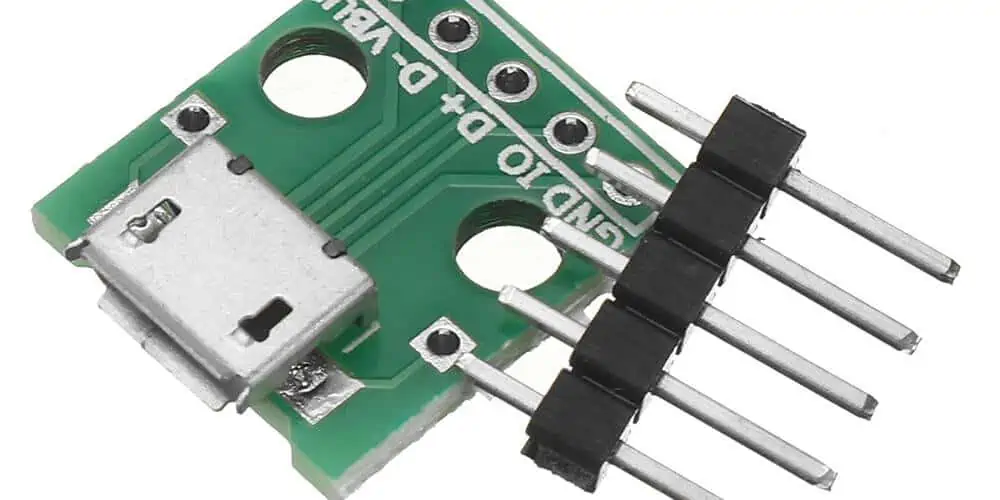
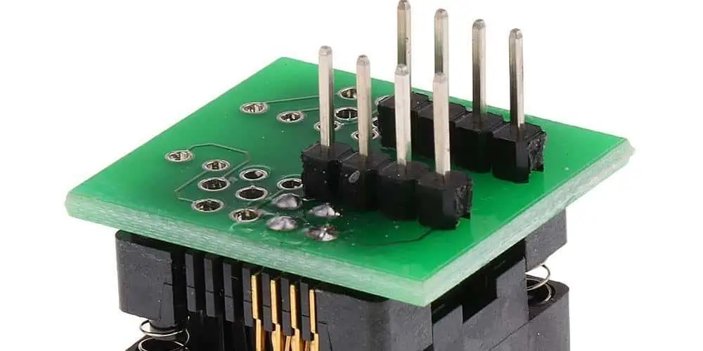
The PCB socket can be frequently utilized to create mounting space on the circuit board for different integrated circuits, also known as chips or ICs. Rows of different pins are seen on the underside of a PCB socket.

Depending on what type of Integrated Circuit it will be utilized for, different sockets feature different amounts of pins. Holes in rows which match the pins can be found on the socket’s upper side. Plastic that is not conducting makes up the socket. Whenever a chip is inserted into a PCB socket, then each leg would be in contact with one of its socket’s legs because each hole provides access to all the pins underneath.

By inserting each socket leg in a corresponding hole on the circuit board, this PCB socket will be directly mounted onto the PCB. The printed circuits in these holes connect them to other parts of the board. After the socket has been installed on the circuit board, it is either manually or automatically soldered into place.

The circuit board is prepared to receive its integrated circuit once this PCB socket has been soldered to it. The IC is put into the socket after each pin is precisely lined up with its holes. As soon as the chip gets inserted into the socket, then it functions just as though it were directly connected to the printed circuit boards.

Importance of Socket PCB

PCB Socket

The installment of a PCB socket during the manufacturing process of a printed circuit board includes an additional step to the process. However, a socket PCB lays a significant role in the functioning of the board. If there is any need to replace the integrated circuit maybe as a result of upgrade or failure, the IC can be easily removed out of the socket and it can be simply replaced by a new chip.

However, if the socket PCB isnโ€™t integrated, the old chip needs de-soldering if a chip needs replacement. This can result in the damage of the printed circuit board and in this case, you need to solder the new chip. Also, the PCB socket is very easy to use and it has no damage risk to the printed circuit board. This is because soldering is not required.

Furthermore, PCB sockets are components lead sockets for unplugging and plugging components on circuit boards. These sockets are ideal for applications exposed to high levels of shock and vibration. Also, the manufacturing of PCB sockets involves press-fitting a pre-tooled contact into a precision machined shell. Furthermore, these receptacles will receive round pins that range in diameter from .008 inches to .102 inches. Also, the rectangular and square component leads are available in different sizes and shapes.

What are the Features of a Socket PCB?

  • A nonconductive plastic is used in making the socket
  • The socket PCB comprises several pins on its underside. These pins are in rows.
  • PCB sockets are very easy to use and they hardly cause any damage to the circuit board
  • Also, the PCB socket is usually mounted on the PCB by placing each of the socket legs on the PCB hole

What are the Different Types of PCB Socket Designs?

FULL PCB MANUFACTURING Quote

There are different types of PCB socket designs. These include:

Throughboard two-piece sockets

Two-piece socket comprises an outer Brass shell. This shell holds Berylium Copper contact clip with 6 or 4 contact fingers. Also, the brass shell safeguards the chip and offers strength to the chip. The clip contact fingers offer the mechanic force need to make positive electrical contact.

The design of this socket is similar to M300 contacts. The throughboard two-piece sockets are ideal for applications that require durability and vibration-resistance. Also, the throughboard design is usually soldered to the circuit board on the underside. This is opposite to the entry point. Furthermore, some designs may comprise a knurl feature on the body. This helps in enhancing mechanical retention in the circuit board before soldering and after. Also, there are open-ended designs for use.

  • The 6-finger and 4-finger designs help in ensuring there is electrical contact via high shock and vibration.
  • There is Beryllium Copper to enhance the temperature range from 55ยฐC to +125ยฐC
  • Mating pin sizes are available in ร˜2.00mm, ร˜0.80mm, ร˜0.50mm, ร˜1.00mm
  • Has about 1,000 mating cycles

SYCAMORE Contact: 3-Beam SMT Single-Piece Socket

This is a single piece socket. This socket is made from a strip of Beryllium Copper. Also, it integrates SMT wings and three contact fingers within the design. Furthermore, you can supply these designs in reel and tape, available for volume automated placement.

This design is much more cost-effective than two-piece socket due to the integration of automation during the circuit board assembly. Also, lower material use contributes to its cost effectiveness.

  • The 3-beam design helps in achieving 500 mating cycles
  • The Beryllium Copper helps in enhancing the temperature range from-50ยฐC to +125ยฐC
  • There are top and bottom entry variations
  • The mating pin sizes are usually available from ร˜0.8mm to ร˜1.9mm

Twin-Beam SMT Single-Piece Socket

The twin-beam SMT single-piece socket is specially made from Phosphor Bronze. It features two contact fingers and there is a central opening via the surface of the material surface for mating pin. Therefore, this provides the least PCB height of the three designs. Also, these designs are available in reel and tape. They are available for automated placement. This cost-effective PCB socket is a suitable option for static equipment installations.

  • There are available mating pins from ร˜0.8mm to ร˜1.8mm
  • The range of operating temperature is between -40ยฐC to +105ยฐC
  • It is low profile and lightweight

Some Important Aspects of Socket Development

pcb socket
pcb socket

In the conventional sense, a socket’s job is to connect the electronic component’s connecting pins, like an integrated circuit, in order to securely grab the contact and create a solid connection. When the electronic industry first began to expand during 1980s, the integrated circuits came as exceedingly expensive parts.

Appropriate sockets were created to enable replacement and prevent soldering them on the circuit board. There are numerous socket kinds as a result of the various IC component designs and their various connecting connections. Both row-row spacing and grid contact must be observed.

The dual-in-line (DIL) variant, which is the most frequently discovered form, is for the DIL ICs. Additionally, there are sockets with a round shape for transistors with various poles that are specially made for the power transistors, quartz oscillators, including sockets made of plastic that is highly heat-resistant.

There are additional frame types that are still in use today. The J-shaped connection type on these integrated circuit modules, works in tandem with the associated fitting to create a spring and clamping contact.

What Distinguishes a PCB Socket from the PCB Connector?

When viewed from the outside, sockets as well as PCB connectors seem to have no connection at all. They can be used in many various technical applications.

Upon closer inspection, both do share a number of traits, and as a result, they can occasionally seem quite similar regarding specifics. Electronic circuit components are held in sockets, which come in different range of styles, sizes, and connections.

In the case of damage, the technician must have the ability of replacing the damaged components simply and quickly without placing undue strain on the solder joints of that circuit boards. The three main purposes of circuit board connections are powering the assembly, transferring data, and connecting circuit boards onto one another. In this case, designs with comparable intricate architecture should be taken into account.

Relationship between Sockets and PCB Connector

Regarding individual contacts, a socket headers’ structure is comparable to or perhaps entirely identical to those of other sockets. This socket connection like with sockets can be utilized when choosing precise contact types. The contacts of the socket must match the pins’ cross-section plug in as the sole requirement.

Also, the IC modules’ connection pins can fit circular pins that measure 0.5 mm in diameter. As a result, a mating strip is often made with 0.5 mm diameter round connectors on its plug in area. Early pcb connector development was primarily based on precision contacts, comparable to those used in the integrated circuit sockets.

In double and single row strips, they are primarily utilized. Also, there are several three row as well as four row design variations.

Designing the single row as well as double strips to be able to be connected together will make using multi row strips more affordable.

Naturally, socket contacts are required to be bigger for larger contact cross sections, like the square pin, which has contacts including a 0.635mm edge dimension. To ensure a better secure connection, its inner spring can be frequently chosen having about 6 main contact fingers rather than four.

The sleeve, as well as their inner contact springs, are the two components that make up the precision socket contact. This inner spring gets rolled and punched as the sleeve rotates. It is put into this sleeve and then fitted with a help of the press fit after receiving a galvanic coating.

Process of Soldering and Selection of Plastic

Correction of PCB connectors and sockets is accomplished by soldering operations. This covers component-safe vapour soldering as well as different “reflow” soldering techniques, including wave soldering method. High-temperature qualities and uses for that insulating material were developed recently.

However, because of the high temperature of soldering used in SMT soldering, the demands placed on the sockets and connectors have greatly grown.

While temperatures of about 260ยฐC are typical when using SMT soldering methods, these connectors are hardly ever exposed to a typical maximum temperature load when using wave soldering procedure. Also, the insulating bodies were supposed to be constructed of plastic which is adequately high-temperature resistant.

Using separate polymers for the process of wave soldering as well as the process of SMT soldering with this same design for that insulating body seems barely worthwhile for smaller makers of sockets and connectors. Therefore, regardless of your soldering procedure, it is advised to always utilize a plastic that can resist high temperature for all the identical designs.

Additionally, only advanced plastics like those from LCP group (polymers that are liquid and crystalline) could be employed for components with exceptionally thin walls. However, for this, the appropriate molding tools must be used, which necessitate that they be properly matched, entirely form-fitting, as well as created with great precision owing to its thin-bodied plastic.

Also, both tool technology as well as machine technology must respect the molds’ temperature management, which is above 130ยฐC. This implies that even with an extremely long path for the flow, even the thinnest wall thicknesses could be reliably filled. This is made possible by its molecular structure, which consists of rod-shaped, rigid, macromolecules that line up parallel to one another within the melts.

Conclusion

Individual lead sockets called PCB Sockets are generally used to plug and unplug components on computer boards. Mill-Max type of PCB sockets are created by pressing a multi-finger pre-tooled contact into the precisely machined shell. These sockets are ideal for applications that are exposed to significant vibration and stress. These receptacles come in a variety of sizes and forms and may accommodate rectangular and square component leads as well as round pins with a diameter of .008″ to about .102″. Every form of design for the PCB Socket has advantages of its own, therefore this article did well to offer some evaluations to assist you in making the best decision for your requirements.

Types and Applications of a Special PCB

Rogers RO4835T PCB

PCB has developed for the past few years. It has developed from the regular board for components to the circuit board with complex components.

As PCB designer or manufacturer, you constantly face challenges on how to achieve a better outcome. You want to provide a new solution or breakthrough to problems. In some cases these problems may require new functionality. It could also be a choice between a module-based or custom PCB design. In any of these cases, you need special PCB types. The ever-growing demand to provide electronic capabilities like high speed or high power into odd spaces made special circuit board types crucial.

ย There may be reasons for this apprehension. Your PCB assembly and fabrication will become successful if you work with right contract manufacturer (CM). To have a clear knowledge of what a special PCB is, we will first define printed circuit boards according to their mechanical and electrical properties which you can use to define your board requirements. Furthermore, we will discuss how manufacturing printed circuit boards with special materials affect turnaround time and cost.

What is a Special PCB?

The Multi-layers High Glass Transition (TG) Printed Circuit Boards Manufacturer

If PCB was classified based on its material, special PCB can be FR4 PCB or metal core PCB. Special PCBs have special requirements. This is a reason they are known as special PCBs. For instance, special PCBs like buried and blind unique, 10 oz heavy copper, and high frequency boards have special requirements.

Special PCB can realize both electrical and mechanical functions. Furthermore, extreme factors like copper thickness, precision, and the PCB thickness are becoming the focus.

Special PCB Types

Ceramic PCB: This printed circuit board features high reliable volume electronic, exceptional high pressure, high frequency, and high insulation.

High frequency RF boards: High frequency RF PCB makes use of Taconic, Rogers, and some high frequency materials. The frequency of this material ranges between 300MHz ~ 3GHz.

Impedance controlled PCB: This circuit board is available in 100 ohms, 50 ohms. The tolerance can be +-10%.

Heavy copper PCB: The copper weight of heavy copper boards is 4~10 OZ/ft2. Extreme heavy copper PCB has a copper weight of 20~200 OZ/ft2.

Carbon ink PCB:ย Carbon ink PCB is said to have a normal resistance if the resistance is 500 ohm or 100 ohms. The resistance could be as high as 10,000 ohms.

How to Optimize Special PCB Board Manufacturing Process

The materials used for printed circuit boards primarily define their properties. Therefore, it is crucial to choose the best PCB material. The choice of the PCB material is an aspect of PCB design. However, PCB designers need to explore the properties of a board if the PCB board material doesnโ€™t satisfy the board requirements.

Furthermore, there are parameters you CM must consider during the manufacturing process of special PCBs. These parameters include type of material, light copper weight, trace width, size, heavy copper weight, surface finish, and more. These parameters can affect the manufacturing process as regards cost and turnaround time.

As PCB designer or manufacturer, you constantly face challenges on how to achieve a better outcome. You want to provide a new solution or breakthrough to problems. In some cases these problems may require new functionality. It could also be a choice between a module-based or custom PCB design. In any of these cases, you need special PCB types.

Special PCB Technologies

FULL PCB MANUFACTURING Quote

HDI blind buried hole

You can only see blind holes on the top or bottom layers. This means that blind holes are usually created from the PCB surface. On the other hand, both sides of buried holes are inside the PCB layers. Buried holes are usually drilled in the inner layer. This means that a buried hole is a type of hole inside circuit boards. Blind buried holes have helped in reducing the quality and size of High-Density Interconnect (HDI) PCBs. Also, these holes help in enhancing electromagnetic compatibility, minimizing the number of layers, making PCB design faster, and reducing costs.

The integration of blind buried hole in the FR-4 prototype has advanced to the highest level of 20 layers. Also, the board thickness is โ‰ค6.0mm, blind holes stage is 1~4, and laser drilling technology is integrated.

Multi-layer special stack-up structure

The ever-growing demands for high-speed circuits have made the complexity of PCB boards become higher.  There is a need to separate the power layer and the signal layer to prevent the interruption of electrical factors. Therefore, multiple layers are involved in this process.

Furthermore, the stack-up structure is plays a significant role in electromagnetic compatibility (EMC) performance of the circuit boards. Also, it is a critical way to reduce electromagnetic interference. For the number of signal networks, the PIN density will be greater if the device density is greater. In this case, a special stack-up structure is needed.

Impedance control

Characteristic impedance refers to the resistance electromagnetic waves or high-frequency signals encounter in the transmission signal lines of components. The PCB characteristic impedance value must correspond with the tail and head componentsโ€™ electronic impedance when transmitting the digital signal on the circuit board.

In a case where mismatch occurs, there will be reflection, delay, attenuation, and scattering of transmitted signal energy. In this case, the PCB designer must carry out impedance control. For FR-4, flexible circuit board, a rigid-flex board, the process of impedance control can help achieve 2โ€“20 layers.

Thick copper PCB

A thick copper PCB is a type of printed circuit board in which the thickness of the copper is 2 oz or beyond. Also, the thick copper circuit board features corrosion resistance, low temperature resistance, high temperature resistance, and great extension performance. These properties enable electronic devices to have a longer life span. Also, they help in simplifying the size of electronic equipment. Some PCB designers can achieve 2~6 layers in thick copper PCB technology. 10 oz is the maximum copper thickness.

Electroless Nickel Electroless Palladium Immersion Gold(ENEPIG)

The Electroless Nickel Electroless Palladium Immersion Gold(ENEPIG) is a commonly used surface finish type used in circuit boards. The ENEPIG process involves depositing nickel, palladium, and gold on the PCB surface by chemical methods. This surface finish technology is non-selective.

This surface finish option integrates 50 nm thick palladium plating and 10 nm thick gold plating. The integration of these plating helps in achieving anti-friction, corrosion resistance, and good electrical conductivity. The copper layer thickness will impact the different appearance and physical properties mentioned above. ENEPIG is the most recent surface finish technology integrated in the PCB prototype. plated pad

Electroplated nickel gold/gold finger

Nickel electroplating is also known as electrolytic gold. This surface finish type attaches gold particles to the circuit board by integrating electroplating. It is usually called hard gold since its strong adhesion. ย This process of attaching gold particles can help to improve the wear resistance and the hardness the circuit board. Also, it can prevent copper and other metals from diffusing. Furthermore, it can meet the requirements of brazing and hot press welding. The coating can have good ductility, low stress, and low porosity. Therefore, coating is widely integrated in PCB proofing.

Considerations for Choosing a Manufacturer for your Special PCB

Isola FR408 PCB

There are several special PCB manufacturers. When choosing a manufacturer for your special board, it is crucial you consider some factors.

Expertise

Special PCBs like heavy copper board, ceramic PCB, and high frequency board require great skill and knowledge during their manufacturing process. Your manufacturer must have a vast knowledge in the design and production of this PCB. Also, you can get more information from review of customers.

Certification

Your special PCB manufacturer must adhere to certain standards in the industry. Also, ensure the company you are hiring has the right certification. Certification implies that your PCB manufacturer adheres to certain standards in the industry. Also, it indicates the quality of the printed circuit board your manufacturer supplies. The right certification assures you your manufacturer is on the right track.

Experience

This is another factor you need to consider when choosing a manufacturer for your special PCB project. Some manufacturers have a long standing experience in fabricating special PCBs. The years of experience your PCB manufacturer has acquired indicates how well they have been performing.

Turnaround time

Turnaround time is an essential factor to consider when choosing a special PCB manufacturer. This factor describes the time it takes to complete the fabrication of a printed circuit board. Before you request for a circuit board, make enquiry about your manufacturerโ€™s turnaround time.

Customer support

This is an important factor you need to consider when choosing a manufacturer for your special PCB. Your manufacturer should be attentive to all your needs and details. Also, some PCB manufacturers offer after sale services to their clients. Consider a manufacturer who puts your interest first.

Conclusion

Some PCB manufacturers offer customers special PCBs. If you have decided to go for special printed circuit boards.  Cart buy The ever-growing demand to provide electronic capabilities like high speed or high power into odd spaces made special circuit board types crucial.

5G Nationwide Vs 5G Ultra Wideband – Which Offers Higher Performance?

5G Nationwide Vs 5G Ultra Wideband

The most recent technology standard for cellular communications is the 5G.  The 5G technology is now the leading standard for wireless communication and connection. This technology has grown in popularity since it was introduced in the year 2019.

Also, the 5G technology promises to offers faster data transfer speeds. Also, 5G can handle large amount of data and offers little to no lag. All these capabilities contributed to the popularity of 5G across different countries. Also, 5G has posed to revolutionize every sector from entertainment to smart technologies. In this article, we will be discussing 5G nationwide Vs 5G Ultra Wideband.

What is 5G?

5G refers to fifth generation technology. It is the latest generation technology for broadband cellular networks. It is about much faster than 4G, about 100 times faster. 5G provides great speed with near-zero lag for a faster and more satisfying mobile experience.

With 5G, you can game, work, watch, and listen online faster than ever before. This cellular broadband communication helps in creating a more sustainable, safer, and smarter future. Since its deployment in 2019, 5G has been offering great capabilities. It has dominated tech new headlines for a while now.

Before the advent of 5G, there were other versions of mobile technology. These include 1G, 2G, 3G, and 4G. 1G was deployed around the 1980s. As the first data network, it introduce analog voice services. 2G was deployed in the 1990s and introduced digital voice services, CDMA. In the early 2000s, the 3G technology paved way for mobile data. The 4G technology is the fourth generation of technology. It was the latest generation of cellular networks before 5G.

5G will not just enhance your network connection, it provides more and newer opportunities. This cellular network was specially designed to offer better and faster connections. It is not only ideal for cell phones, but it also ideal for compatible devices. This means your personal computers can integrate the 5G wireless technology.

What is 5G Nationwide?

5G Nationwide

5G Nationwide integrates 4G LTE networks and lower spectrum 5G.Also, 5G Nationwide makes use of a new antenna technology to run 5G and 4G LTE in a frequency band. Therefore, you can use 5G in areas where there is availability of service, and as well switch to 4G or 4G LTE in areas that have no higher-speed service.

The 5G Nationwide is just like a new standard for seamless 5G connectivity. The combination of 4G LTE and lower spectrum 5g both technologies helps the carrier to ensure convenience for both 5G and 4G/4G LTE users. Users of the 5G nationwide have continued to experience great and consistent connectivity across most areas in the country.

Presently, 5G nationwide is available in some areas. It has coverage in more than 2,700 cities. The integration of Ultra Wideband is presently going on. However, this may take some time to adopt. Presently, ultra wideband has a wide coverage in some cities. You can check the 5G coverage map to know if your service area provides it.

5G nationwide offers a wider coverage both outdoors and indoors, all thanks to its low-band spectrum. This network is the most widely available 5G provided by Verizon.

What is 5G Ultra Wideband?

5G Ultra Wideband delivers the highest performance and the fastest possible 5G speeds by using high-band, ultra-wide mmWave spectrum. 5G Ultra Wideband offers users with near-zero lag experience, which enables you to stream high picture-quality movies, play games effortlessly, and make video calls.

The capabilities of  5G Ultra Wideband is top-notch. Also, 5G ultra wide band can offer high data transfer speed to phone users without slowing down local data transfers.  5G Ultra Wideband has proved to revolutionize several sectors such as healthcare, entertainment, public works, and automotive.

The major difference between 5G Ultra Wideband and 5G Nationwide 5G is their location and speed. While 5G nationwide has a larger service area than 5G Ultra Wideband, the 5G Ultra Wideband is faster.

This doesnโ€™t indicate that users are restricted to particular locations with 5G Ultra Wideband. Your network will switch to 5G nationwide automatically once you move away from areas with Ultra Wideband coverage. The 5G nationwide provides 4G LTE, 4G, or 5G based on your location.

Ultra Wideband 5G can handle large capacity. This indicates that this network provides reliable performance in places.

What Does 5G Ultra Wideband Offer?

5G cellular technology standard can carry out better leaps and bounds than the 4G/4G LTE standard in three crucial aspects which are:

Speed

5G Ultra Wideband provides very high upload speeds and download speeds which are 200+ Mbps and 4+ Gbps respectively. Also, this is different from the average 4G speeds of almost 30-35 Mbps. This means that you can download high-definition movie such as a 4K definition movie at a very fast speed. You will download the movie just as you click on the title.

Latency

When it comes to latency, 5G Ultra Wideband offers a very low one. This means online streaming, gaming, video chatting, and entertainment seem like they occur in real time.

Capacity

In terms of capacity, Ultra Wideband 5G can handle large capacity. This indicates that this network provides reliable performance in places such as airports, stadiums, and other populated venues. Therefore, you may likely experience a fewer issues in places where many people are on their phones at the same time.

Benefits of 5G Ultra Wideband

FULL PCB MANUFACTURING Quote

5G ultra wideband offers a lot of benefits which include:

  • Much faster speeds than public Wi-Fi. With 5G ultra wideband, you no longer struggle with slow speeds anytime you go online. You are always on the go. Also, you can be 100% assured of smooth browsing. 5G ultra wideband gives you less or no worry about snoopers.
  • The 5G ultra wideband isnโ€™t only suitable for mobile phones. You can use it in your homes and offices. With this network, you can enjoy fast internets and connect lot of devices. Also, you donโ€™t need cable to install the 5G ultra wideband.
  • You can download faster with the 5G ultra wideband. It is 10x faster than Wi-Fi. Therefore, you can get your movies downloaded in minutes or your songs downloaded in a matter of seconds.
  • 5G ultra wideband has a very wide coverage. It is specially designed for places where a large number of people can use their phones at the same time. Even thousands of people can stream, post, and download without struggling with slow speed.
  • Audio and video in HD. Therefore, you can stream video without Wi-Fi.

5G Nationwide Vs 5G Ultra Wideband

The major difference between 5G nationwide Vs 5G ultra wideband is their location and speed. 5G ultra wideband offers faster speed while 5G nationwide offers fast speeds with a wider service area. You donโ€™t need to choose between these networks. Also, 5G ultra wideband and 5G nationwide both offer low lag wireless performance.

You donโ€™t need to choose. You will be on 5G nationwide when you leave an area that has an Ultra wideband-covered area. Also, you can still access the dependable countrywide 4G/4G LTE network, if you arenโ€™t in an area with 5G coverage.

5G ultra wideband is just a marketing name. It is totally different from the ultra-wideband radio technology.  Devices such as Samsungโ€™s Galaxy SmartTag and Appleโ€™s AirTag integrate the ultra-wideband radio technology.  Verizon used the 5G ultra wideband as a marketing name. When you are in the 5G ultra wideband network, a distinct 5G icon will display on your screen. This icon displays extra characters such as โ€œUWB or โ€œUW.โ€

5G nationwide is available in more than 2,700 cities while 5G ultra wideband is available in some selected cities. In the cities where there is availability of 5G nationwide, devices having 5G display a 5G icon on their screen. ย You can still experience a good network with 5G nationwide even if you arenโ€™t in an area with 5G ultra wideband coverage.

The highest performing 5G offered by Verizon is 5G ultra wideband. Verizonโ€™s 5G ultra wideband network integrates mid-band and high band spectrum to offer a top-notch 5G experience. Also, 5G ultra wideband offers great benefits such as speeds which are 10 times faster.

On the other hand, 5G nationwide utilizes a low-band spectrum to offer good coverage and great performance. Also, 5G nationwide is available across the US.

C-band, Low Frequency, and mmWave

5G connections depend on radio waves called spectrum. This spectrum can operate at a wide range of frequencies. 5G uses three ranges of frequencies. The first one is the low frequency spectrum which is around 4GHz. This spectrum can travel at a very long distance and has the ability to penetrate obstacles like wind and buildings. Therefore, it is a more convenient way to create 5G coverage.

However, the low frequency spectrum doesnโ€™t offer support to high speeds. It always comes in just a bit faster than 4G LTE. Download speeds can be more than 100 Mbps at average. However, it rarely passes 200Mbps. Therefore, you will have to migrate to a higher frequency spectrum like C-band to enhance the speed. This band covers frequencies within 4-8 GHz. US carriers are considering C-band as a spectrum that falls in the 3.7-3.98GHz.

However, this band supports higher speeds. Although, it is not robust enough to pass through obstacles, it performs well. According to TechRadar, 474.51 Mbps was recorded using C-band 5G.

There is another spectrum which refers to mmWave (or millimeter wave). The mmWave is a spectrum of 24GHz and more. Also, the mmWave is not commonly integrated as the lower frequencies. The mmWave has a limited coverage, although it is being used in the United States.

The reason behind this is that it is tricky to offer mmWave coverage. mmWaves has its weakness which are its struggles with hindrances and short range. On the other hand, low frequency spectrum can penetrate obstacles and also has long range. However, an mmWave signal is super fast, offering speeds of more than 1Gbps.

Verizonโ€™s 5G ultra wideband network integrates mid-band and high band spectrum to offer a top-notch 5G experience.

Frequently Asked Questions

5G PCB
5G PCB

What is the major difference between 5G nationwide vs 5G ultra wideband?

The major difference between 5G nationwide Vs 5G ultra wideband is their location and speed. 5G ultra wideband offers faster speed while 5G nationwide offers fast speeds with a wider service area. You donโ€™t need to choose between these networks.

What does the 5G ultra wideband icon mean?

The 5G ultra wideband icon will display on your status bar. Also, 5G icon will pop up on 5G devices when they are connected to 5G ultra wideband or 5G nationwide. However, these icons vary based on your provider.

Is 5G ultra wideband for offices and homes?

5G ultra wideband powers the 5G internet offered by Verizon.  The 5G ultra wideband is available for businesses and homes in some select areas. 5G internet provided by Verizon offers speeds much better than traditional cable internet. This 5G internet is available at a very low cost. Also, it is unlimited unlike cable providers.

How fast is 5G ultra wideband?

The fastest 5G in the world is 5G ultra wideband. It is much faster than 5G nationwide and AT&Tโ€™s 5G. Verizonโ€™s 5T ultra wideband deliver a maximum download speed that is much faster than 1.0 gigabits per second. This means a 600MB video can be downloaded within 34 seconds.

Does 5G nationwide offer a better coverage?

Yes, 5G nationwide offers a wider coverage both outdoors and indoors, all thanks to its low-band spectrum. This network is the most widely available 5G provided by Verizon.

Conclusion

5G Ultra Wideband delivers the highest performance and the fastest possible 5G speeds by using high-band, ultra-wide mmWave spectrum. 5G Ultra Wideband offers users with near-zero lag experience, which enables you to stream high picture-quality movies, play games effortlessly, and make video calls. The major difference between 5G nationwide Vs 5G ultra wideband is their location and speed. 5G ultra wideband offers faster speed while 5G nationwide offers fast speeds with a wider service area.

Accelerometer vs Gyroscope: What are the Main Differences?

Accelerometer vs Gyroscope

Every year, the consumer electronics industry grows quicker. People are now more aware regarding the ways in which technology might benefit them due to this. The use of accelerometers and gyroscopes has become more widespread. MEMS, or Microelectromechanical systems, are increasingly important in these technologies. They provide the consumer a fresh method of interacting with their gadget. Additionally, they detect the motion of the device and then have interactions with them in some new ways.

Both the industrial and consumer markets can benefit from these gadgets. The aerospace and automotive sectors are among them. Here, MEMS would detect motion in different automobiles like cars, ships, and planes. These sensors can also be used to detect direction and speed. It will boost these products’ general effectiveness.

MEMS are used in seat detectors, side-impact airbags, as well as control units of airbags. Inside the automotive sector, they are also utilized in cruise controllers. Consoles for video games can also benefit from the accelerometer and a gyroscope. It is a prime illustration of consumer technology. Before transferring the data from this device into the console as well as the gaming platform, a microchip processes it. Before we go into accelerometer vs gyroscope comparison, letโ€™s know what an accelerometer is.

What Does an Accelerometer Mean?

Accelerometer Gyroscope

A tool used to measure an object’s acceleration while it is falling freely is an accelerometer. A linkage, spring, and mass make up the mechanism. They hung the mass out from replaceable linkage from its resting position. A vertically accelerating object will cause the hanging mass to move in the opposite direction.

The amount of acceleration that this object is experiencing is determined by its mass displacement.

The accelerometer measures an object’s acceleration to perform its purpose. The uses for an accelerometer are countless. Because various species use it in detecting gravity or even the gravity of the earth, it is typically utilized by nature. They are used by some scientific institutes to measure cosmic acceleration and rotation rates. These devices operate due to certain forces. MEMS, IVI, Gyroscopes, as well as Magnetometers are a few of them.

How Does it Work?

Free-falling means that an object is descending because of gravity. Depending on the weight of the object, this object will eventually attain a specific speed. The acceleration brought on by gravity would be denoted as “g”.

The mass is subsequently subjected to a specific physical force, which causes it to slow down. The deceleration is tracked by an accelerometer. It calculates the momentum shift brought on by the force, which alters when there’s an accelerating force acting on it.

The Piezoelectric Effect

The accelerometer also functions in conjunction with this phenomenon. Whenever you compress a crystal containing bonded atoms, it develops a electrical charge. It produces a voltage when compressed. When this device is connected, it will start to function as the accelerometer.

Capacitance Change

An accelerometer functions by detecting changes in the capacitance in certain applications. Thus, whenever it is falling freely, it experiences changes in capacitance. There are two capacitive plates. They are linked via a capacitor and a coil. The system tracks the capacitance’s variation. It can be used to establish whether something is falling.

Magneto-resistive effect

FULL PCB MANUFACTURING Quote

The magneto-resistive effect is also a component of an accelerometer. A faint magnetic field is detected. It thus recognizes the acceleration brought on by magnetic fields.

MEMS Accelerometers

Different operating principles are required for accelerometers. They are employed in the automotive, consumer electronics, as well as aerospace sectors. The most well-known MEMS device is the accelerometer. It can be used to detect shock, vibration, and slight changes in an object’s direction.

It uses extremely little power whenever in operation, making it a highly efficient device as well. Because of this, you may decide to leave it for long without the battery of the device draining.

Accelerometers’ main component is a technology known as Microelectromechanical systems, otherwise known as MEMS. They quantify vibration, rotation, and acceleration. By tracking the movement of the proof mass, we can calculate the acceleration. In addition to the resonant structure, there is a proof mass.

The electromechanical sensor is the most used kind of accelerometer. As a result, we also call it an accelerometer. Typically, accelerometers consist of integrated circuit and sensor chip. It includes resonators, inductors, and capacitors (tuned circuits having resonant frequencies).

This sensor chip may use conventional CMOS technology, silicon-based, or alternative techniques. The acceleration measurement system makes use of piezoelectric effect. The system tracks the capacitance’s change.

What are the Applications of an Accelerometer?

Accelerometer and Gyroscope

There are several uses for accelerometers, including:

Compass/Mapping programs:

Accelerometers are used in systems for GPS navigation to determine whether the object is moving. It would also be able to determine which way it is traveling. Tablets and phones may establish their direction and orientation via axis-based sensing.

Detection of Earthquakes

The detection of earthquakes is done using accelerometers. Also, it helps in determining the movement’s magnitude.

In-car applications

The accelerometers are used in automobiles to check whether the driver is still controlling his or her vehicle. A proper safety response is then triggered.

Tilt sensing

By using the gyroscope and an accelerometer, we can determine the orientation of a device. IPhone, for instance, makes use of a gyroscope and accelerometer. When a user turns their phone from the portrait mode to the landscape mode, it first recognizes this. It then modifies the applications as necessary.

Fall Sensing

In sophisticated protection systems, accelerometers are used. They recognize a fall, then they activate life-saving features like seat belts and airbags.

Fitness monitors and wearables

Accelerometers can spot movement. This can determine whether the person is cycling, walking, or running.

Medical Devices

Medical Devices Additionally, it provides vital information regarding a patient’s condition. Accelerometers are also seen in artificial hips and heart valves. They aid in the detection of motion near the prosthesis.

Applications and games

Accelerators are useful in detecting movements when a game is on. i.e. the joystick controller’s response time.

What Does a Gyroscope Offer?

The gyroscope can be described as a tool that gauges an object’s rotation rate by using its own inherent inertia. It’s a form of mechanical effect, in our opinion. Gyroscopes are used in a variety of electronic applications as well as geophysical and space exploration.

How Does a Gyroscope Work?

The two primary components of a gyroscope are:

  • Pair of gyroscopes, which are weighted rings.
  • A magnetometer, which is a device that measures angular rate but we don’t make use of.

The precession phenomenon that occurs whenever the gyroscope rotates round one axes is how it functions. When it takes on an equilibrium state, it is unable to discern the rotation angle. But when it has rotated, it will face up toward the axis you positioned it on.

In this instance, a gyroscope-affecting inertial force is at play. A greater amount of kinetic energy would accompany this motion because its angular momentum is unchanged. The gyroscope will move backward due to this force. But since the gyroscope remains stationary, we refer to this as the precession. A gyroscope would reject any change coming to the angular momentum till you add torque, which is another precession phenomenon.

The rate whereby a specific object rotates inside a accelerating frame can be determined from its rotation rate in a inertial frame. It accomplishes this using either Newton’s first motion law or the equivalence principle of Einstein.

What are the Applications of Gyroscopes?

Gyroscopes are mostly used for space exploration navigation, as well as flight control. They are beneficial for medical equipment as well, though. Heart monitors as well as other medical devices are an illustration. Gyroscopes are also used by NMR spectrometers for monitoring motion.

Systems for inertial guidance

For rockets, missiles, spacecraft, including unmanned aerial vehicles, systems for inertial guiding are crucial. Orientation and position in space can be determined via the system for inertial guiding

MEMS gyroscopes are used in consumer electronics.

Consumer devices, notably tablets and smartphones are driving up MEMS demand. This is due to the majority of modern tablets and smartphones have the 3-axis gyroscope.

When a device starts moving far too much, gyroscopes can identify it. For instance, in a collision, it would activate the airbag system. It will make a GPS-based call to emergency services if it notices a significant ground fall.

Stability in ships, motorcycles, as well as vehicles

The vehicle’s longitudinal and lateral stability parameters can be ascertained using MEMS gyroscopes. It allows us to evaluate how the chassis of a car is functioning. Stability is also used in autos. It can tell, for instance, whether a car is unstable or loses balance when navigating a curve.

Airplanes via MEMS gyroscopes

One crucial component is the MEMS module. It makes the fly-by-wire flight control system’s roll axis functional. Pilots may now fly a jet using supersonic speeds thanks to this technology. Vehicle, motorcycle, and ship stability

Space stations

The speed, orientation, as well as the direction of the space station is determined in part by MEMS gyroscopes and accelerometers.

Accelerometer vs Gyroscope: What are the Differences?

There are numerous commonalities between the two sensors whenever compared. You’ll discover they have comparable skills and uses. So figuring out which one functions better is extremely difficult.

You may learn more about the distinctions between accelerometer vs gyroscope in this section. It will then assist you in selecting the appropriate sensor that suits your project.

Function

In measuring acceleration, we utilize accelerometers. A gyroscope, on the contrary, has the ability to gauge both angular velocity and angular rate. In a nutshell, accelerometers detect changes in direction and speed. A gyroscope detects rotational speed.

Rotation sensors and rate gyros are other names for gyroscopes. However, how they perform determines this. It is renowned for sensing angular acceleration and rotation as well as linear acceleration. An accelerometer as well as a gyroscope can also be combined and used to measure.

The gyroscope measures yaw axis motion to determine its angular velocity. Gyroscopes are employed by inertial navigation as well as systems for flight control to measure rotational speed.

Gyroscopes are another type of sensors that robots employ to sense their orientation as well as keep their balance.

Accelerometers can be thought of as tiny gyroscopes. That’s because they measure angular rate similarly.

Horizontal Mode

Basic rotational movement taking the west or east direction, also known as yaw, is measured by a horizontal mode. Depending on whatever axis that gyroscope detects rotation in, yaw could also employ the terms roll or pitch to describe the motion.

Angular velocity measurement

Gyroscopes are devices that measure or detect a rotating body’s rotation. You need to install this gyroscope on any fixed location to regulate the rotation’s direction in order to achieve accurate measurements.

A piece of electronics is the gyroscope. We utilize it for 3D sensing, scanning, navigation, as well as systems for position control and use it to detect angular velocity.

It is not enough to measure linear velocity for inertial navigation systems. This is possible because the spacecraft may move at very high speeds while maintaining alignment. In systems of position control, whereby the vehicle isn’t moving, we can employ it to obtain orientation information.

There are different modes in a gyroscope, including angular rate, horizontal, as well as drift of the angular rate drift. ย Every mode type is necessary for various applications and circumstances.

Ratio of signal to the noise

The ratio in between the level of noise and signal level registered by the detection device is known as its ratio of signal to the noise.

The sensitivity to changes in input increases with the ratio of signal to noise. Choosing a sensor requires consideration of this ratio. This is so that it won’t be accurate or precise. For instance, a sensor having a poor SNR won’t react to minute changes in the output.

A particularly sensitive sensor having a high SNR that can detect even the tiniest changes is the gyroscope. Due to this, accelerometer values are lower, which is counterproductive.

Gyroscopes are used to create the inertial navigation system. This is because they are more sensitive to changes in angular velocity than accelerometers are. When it comes to drift, the gyroscope edges the accelerometer. This results from its continuous measuring mistake.

Conclusion

Hope you know the differences between accelerometer vs gyroscope. Finally, the environmental and application factors will determine which sensor is best. We must first decide which output is greater in a specific application. Getting raw data out of the sensor is possible, then you should choose accelerometer over the gyroscope. However, if what you want is high precision and accuracy, then the gyroscope is preferable over the accelerometer.

Active Filter Vs Passive Filter: Whatโ€™s the Difference?

Electronic filters which filter a particular frequency and perhaps a specific range of different frequencies from the signal include active filters as well as passive filters. They are very different in terms of performance and design aside from their frequency filtering.

Let’s first talk about the fundamentals of passive and active filters before getting into the distinctions between them.

What Does a Filter Mean?

An electrical filter can be described is a circuit which may pass and amplify a specific band of frequencies while blocking or attenuating other frequencies. Also, they are employed to remove particular frequencies from the transmission.

During signal processing, filters are employed to remove noise from signals, extract the message from the signal, etc. There are various kinds of filters, including low-pass, bandpass, high-pass, analog and digital, passive and active, non-linear and linear, etc. The distinctions between passive and active filters will be covered.

Filters have a wide range of applications in the world of electronics. Here are some examples:

Radio communications

With filters, radio receivers will be able to “see” only the targeted signal whilst rejecting other signals in radio communications (Let’s assume that all other signals feature different frequency contents).

Direct Current power supplies

Here, the filters are utilized in removing noise (unwanted high frequencies) from the input lines of the AC. To lessen ripple, filters are also applied to the output of a power supply.

Audio Electronics

In the field of audio electronics, the crossover network refers to a system of filters utilized to distribute low-frequency audio into woofers, sounds of high-frequency into tweeters, as well as mid-range frequencies into midrange speakers.

Analog-to-digital conversion

To reduce aliasing, filters are inserted in the front of the ADC input.

What Does an Active Filter Mean?

Passive Filter

Active filters are filters designed making use of active components like transistor and op-amp.

They are combined with capacitor and resistor, but excluding the inductor. These filters have the ability to increase power. However, in contrast to the passive filters, its design is more sophisticated.

Active filters need an external source of power to function because they utilize active components. The signal after filtering doesn’t need to be amplified. This gain could be altered by changing a particular parameter while the device is operating. The output and input impedances of an op-amp are low and very high respectively.

As a result, the active filter doesn’t face any loading effect issue at its load and source. Additionally, because its load is separate from its source, changing the load has no impact on how well the filter performs.

The need for the external source is the disadvantage of the active filter. The condition of this external source affects how well the filter works. Active filters’ active components have a finite bandwidth. As a result, they are inadequate for high-frequency signal filtering. Additionally, they are more vulnerable to harm from strong current.

The circuit’s op-amp is typically utilized in a specific integrated fashion. So make sure it’s compact and lightweight. Op-amps are known to have a low output and high input impedances. Therefore, its loading effect present at load and source is eliminated by these active filters.

However, active components have limited bandwidth, which occasionally results in problems in operating high-frequency signals. Additionally, this active filtering mechanism requires a dc source because it is unable to draw its driving power out from the input signal.

What are the Characteristics of an Active Filter?

  • Op-amps and transistors are examples of active components used in active filters.
  • Also, it includes passive parts like capacitors and resistors but not inductors.
  • In order to function, it needs external source of power.
  • Its output impedance is very low and its input impedance is extremely high.
  • The filter can be readily cascaded to enhance the filter’s order without having to worry about the amount of the loss.
  • At the output, it offers a substantial power gain.
  • Its electrical properties are unaffected by changes in load resistance.
  • It features sophisticated circuitry.
  • Its design is compact, and its size is small
  • Due to the active components’ limited bandwidth, its frequency range is limited
  • It is more expensive than the passive filters
  • High frequency operation is not possible.
  • It is unable to tolerate strong currents.

What are the Applications of the Active Filters?

  • In communication, active filters play a huge role in cutting through noise, so as to help in isolating signals from different channels, and enhance the distinct message signal coming from the emphasized signal.
  • The designers of instrumentation systems use these filters to identify the necessary frequency apparatus as well as separate unwanted ones.
  • Before converting analog signals into digital signals, active filters may be employed to reduce the bandwidth of the analog signal.
  • Audio systems have active filters to convey different frequencies to different speakers. Applications for recording and playing back music, for instance, are necessary in music to help in controlling its frequency components.
  • These filters connect psychological sensors to diagnostic tools and data logging in biomedical devices.

Benefits of the Active Filters

The following are a few benefits of the active filter

  • No resonance problem
  • They have the ability to completely eliminate harmonics,
  • It helps to regulate voltage,
  • Active filters compensate for reactive power,
  • They operate consistently.

Pitfalls of the Active Filters

  • They are costly
  • The control systems they offer are complex

What Does a Passive Filter Mean?

FULL PCB MANUFACTURING Quote

Only passive parts, such as resistors, inductors, and capacitors, are used in passive filters. It’s relatively affordable and features a simple design. Also, they don’t give any electricity because this filter operates without an external source of power. They do, however, employ an inductor to enable them to handle high current.

Extremely high frequency can be handled by passive components. Passive filters therefore are employed in high-frequency applications. However, extremely low-frequency applications are not appropriate for them. In order to increase the inductance value, a larger, bulkier inductor is needed, which also increases the filter’s size and price.

The filter’s overall resistance is directly impacted by its load resistance. As a result, any modification to this load resistor will alter the filter’s electrical properties. It features a constrained output and input impedance, and loading has an impact on how well they work.

Its output signal features lower magnitude in contrast to its input signal because passive components draw power from its input signal, hence the passive filter somehow doesn’t generate power gain. It needs post-filtering amplification.

Passive filters have good response for the radio frequency band. However, in the low-frequency applications, the circuit’s use of an inductor leads to issues. Similar to the case with low frequencies, its inductor’s inductance should be increased, which necessitates adding more turns to the coil.

Passive filters’ input and output impedances become problematic below the Radiofrequency range. Therefore, low-frequency operations are not well suited for these. In essence, the categorization of filters is produced by the frequency band that is permitted and prohibited.

Characteristics of the Passive Filter

  • Passive filters don’t need an external source of power because they exclusively use passive parts like resistors, capacitors, and inductors.
  • There is no power gain
  • The features of a passive filter are impacted by changes in the load resistance.
  • Because it consists of an inductor, it is free of frequency restrictions and is typically utilized for many high-frequency applications.
  • Because a huge inductor is needed for its the low-frequency applications, its passive filter grows in size and becomes more expensive.
  • The design is straightforward and easy.
  • It has a greater size and is heavier due to larger inductors;
  • It is less expensive than the active filter.

Benefits of the Passive Filter

  • Stability is guaranteed
  • There is no need for power supply
  • It is less expensive
  • Designing it is easy
  • It has a high frequency

Cons of the Passive Filters

  • Their size is large
  • At times, they could have response problems
  • The gain is usually 1 or lesser
  • When utilized with the inductors, it is usually bulky

What are the Applications of the Passive Filters?

Passive filters have many applications. These include:

  • They could be utilized in band pass filters to reject signals at any and all frequencies below and above this band.
  • Also, they can be employed in the high pass filters, particularly in audio amplifiers.
  • They function as I.F. transformers seen in earlier TV and Radio equipment to pass the band of different radio frequencies through one step of an intermediate frequency amplifier.
  • Furthermore, they are employed for band stop filters TV and older radio receivers.

Active Filter vs Passive Filter: What are the Major Differences?

active Filter

The primary distinction between the active filter vs passive filter is that the active components, such as op-amps and transistors, are used by active filters in filtering the electronic signals. In contrast, the passive filter creates a signal for a certain band using passive parts such as an inductor, a resistor, as well as a capacitor.

Another significant difference between these two is whether the active filter requires an external power source to function. While passive filters don’t require an external source.

We are aware that filters are circuits with the capacity to pass through a specific frequency range while rejecting frequencies outside of the band. In essence, filter circuits display the frequency selectivity property. We’ll go over some more variations between active filter vs passive filter.

Due to the existence of the active components, these active filters are costly. On the contrary hand, because they contain passive components, the passive filter is sufficiently affordable. Active filters have a complicated circuit orientation. While the circuit for relatively passive filters are simpler.

In contrast to the passive filters, active filters feature a higher quality factor value and require an external power source to operate. Nevertheless, because they draw the energy necessary for effective operation from its supplied input signal, passive filters don’t really require external sources of energy.

Passive filters are ideal for RF range operating because the inductor, the main component used in them, produces barriers at very low frequencies. Active filters, on the other hand, provide a stronger response for low frequencies.

Passive filters have relatively high weights, compared to active filters’ low weights. Active filters are more sensitive to temperature variations. Passive filters, in contrast, are less susceptible to temperature variations.

Comparison Active Filter vs Passive Filter

Power Source

  • The Active filters need an outside power supply to function.
  • Passive filters don’t need an outside power source in order to work.

Gain

  • The active filters increase output signal as well as offer a significant power gain.
  • A passive filter offers no power benefit. In actuality, this output signal is weaker than its own input signal in magnitude.

Design

  • The design of the active filter is complex in nature
  • The design of the passive filter is simple in nature

Loading Effect

  • Because active filters have high input and low output impedances, loading effect is not a concern.
  • Passive filter does have a problem with the loading effect.

Bandwidth

  • Due to the frequency restrictions of the active components and their constrained bandwidth, active filters are unable to filter signals of high-frequency
  • There are no frequency restrictions for passive filters.

Size

  • Passive filter is heavier due to the size of the inductors and are bulkier, especially at low frequencies when big inductors are required.
  • The Active filter is compact and possesses a small weight and size.

Cost

  • Passive filters are manufactured from inexpensive passive components,
  • Active filters require expensive active components as well as a power source.

Conclusion: Active Filter vs Passive Filter

Therefore, it may be inferred that each type of filter has a specific operating range. However, in the fields of signal processing and communication, the active filter is utilized more frequently than the passive filters.

5 Pin vs 3 Pin Switch: How Do They Differ?

pin switch

Two major mounting styles are available when purchasing switches for the mechanical keyboard: Plate-mounted and PCB-mounted. It can be challenging to distinguish the distinctions, but we’ll clarify what each signifies.

Switches installed on PCBs have five pins, whereas switches located on plates have three. By clipping its extra pins present on the switch’s bottom, a switch for the PCB-mount can be altered to fit the plate-mount.

We’ll examine each of the switch types, as well as their unique characteristics and explain how to adjust the switches so that they fit your circuit board.

PCB Mounted vs Plate-Mounted Switches: What’s the Difference?

Consider the quantity of pins present on its bottom to see the primary distinction between the PCB-mounted as well as a plate-mounted switch. A switch put on the PCB will come with 5 pins, however the plate-mounted which comes with three.

What Does the PCB-Mounted Switch Mean?

Because there are 5 parts altogether on the bottom of PCB-mounted switches, they are known as 5-pin switches.

The switch is held together by four pins: two metal that enable this switch to function, two plastic ones that ensure stability, as well as a central “pin” that more closely resembles a sizable round knob.

These switches could be directly mounted to the Circuit board using solder, making installation rather straightforward.

Guiding pins are also included with the switches to make it easier to install them on the PCB. The keys would typically bounce a little bit more with this style of installation because it generally feels lighter. Smaller keyboards typically employ the PCB mounting approach since they flex less easily and require less support.

Possessing a plate, however, is fairly typical in contemporary boards. Without the plate, a keyboard can be constructed, but the reliability of these switches depends on the soldering job.

What Does a Plate-Mounted Switch Mean?

Switches that are plate-mounted are known as plate-mounted switches. The central circular knob and the two pins made of metal are the only three pins on the switches’ bottom. The pins for stability are absent.

The plate enters the picture here. When the button is pressed, the plate would steady each switch thus lessening side-to-side shaking.

PCB mounting vs. Plate mounting

Switches are mounted to the metal plate which is placed above the Circuit board using the plate-mounting technique. After being inserted into this metal plate, these switches are subsequently soldered to your circuit board.

Due to the keyboard’s tendency to bend more, the plates are frequently utilized with the larger keyboards in order to provide additional support. Also, t he plate makes the keyboard more solid and aids in improving security.

The switches differ significantly from PCB mounted type in that they are put in the plate rather than the PCB, eliminating the requirement for the extra guiding pins. Just bear in mind that the switch plate is going to be challenging to remove once you’ve soldered the switches.

To remove the plate as well as re-solder each of the switches to the Circuit board, you must first remove all the switches. This may not be your best choice if you anticipate making several alterations and revisions.

These plate-mounted keyboards, generally have higher quality as well as have a longer lifespan. This type of installation gives the keys a less rocky and more stable, which some people prefer. Just bear in mind that this arrangement usually costs more because there are more parts and assembly required.

Understanding the 5 Pin vs 3 Pin Switches

FULL PCB MANUFACTURING Quote

While the 5 pin switches feature two tiny plastic legs present on either side of the bottom housing, the 3 pin switches do not. On Circuit boards with the 5 pin compatibility, there are holes for the legs. On either side of your socket, they are situated. The function of these legs is unaffected, but they help to keep this switch more securely placed in its hotswap socket.

Some hotswap Circuit boards do not support the fifth pin. To put the switch on these Circuit boards, you must use miniature hobby clippers to help in clipping the legs. There should just be two legs of plastic that need to be clipped. Keep all metal pins unclipped.

There is no need to take any step to install the 3 pin switch if you already have the 5 pin socket.  However, after removing keycaps, then you could realize the switch is relatively simple to remove from the socket.

There is no clear advantage to one type of switch over another. There will be less support on your switches if you are mounting them without any plate, though. The absence of reinforcement will make the keyboard feel ricketier and also less stable.

You might wish to include a plate to your construction if you type quickly or prefer the feel of the really stable keyboard. Although some people might see it simpler to manufacture, the PCB-mounted version of keyboards are often less expensive to construct because it doesn’t need the additional reinforcing plate.

They support mostly 3-pin switches in majority of hot-swappable boards. In this case, having the 3-pin switches would be useful. This becomes less concern if you’re creating a bespoke keyboard because you may choose which PCB you use.

More on 5 pin vs 3 pin switch

With the exception of its switch puller, most switches on hot-swappable keyboards may be quickly and easily inserted into the “Hot-swappable Mount/Socket” even though they are actually intended to undergo soldering. However, there are two types of switches: 5 pin vs 3 pin switches.

Interestingly, despite the fact that both variations are dependent on the pin count, there is no electrical basis for the differences between them.

A 5 pin switch has 2 extra plastic “legs” (or pins) than the 3 pin switch, which is the real difference. Two additional “legs” (or pins) give the pins of the keyboard more rigidity when inserted. This makes it less probable for the switch to slip from the keyboard whenever in use.

However, 3 pin switches would work on any hot-swappable keyboard which supports the 5 pin switches. However, it is important to note that 3 pin switches could have less stability because they are designed with 2 fewer plastic pins.

In addition, most people are unaware that the switch itself is NOT hot-swappable; rather, the socket or mount on the Circuit board to which the switch connects is. This is because the switch is not soldered into place.

Converting the 5 Pin vs 3 Pin switches

The legs protruding out is the main distinction between the 5 pin vs 3 pin switch connector, as we’ve previously mentioned.

You can cut out the two side legs by using cuticle cutters, flesh cutters, nail clippers, or other ordinary household tools. These metal pins must remain in place for this switch to function and convey signals to the computer, so avoid clipping them.

Take Precautions with the Switch Pins

5 pin switch

Let’s first dissect the parts that make up the hotswap socket present on the PCB of the mechanical keyboard. The metal pins of the switch make contact with and attach to the board through the two bigger holes.

Make sure the pins aren’t deformed during installation. The key may not register properly if they don’t fit into its slot properly. We advise applying light pressure and installing the switches on the softer surface.

Switches should fit into place without requiring excessive force. Remove this switch and inspect the pins if it seem like you have to push firmly to insert it.

Before attempting to reinstall the switch, you can utilize tweezers to help flatten any bent pins. This time, take extra care because the pin has become weaker and will more likely bend.

Slow down and also be intentional

The final piece of advice we have is to proceed slowly and cautiously. Perform study on the hotswap sockets, switches, and particular keyboard you are now using. While it could be tempting to rush the process of installing your switches on the new hotswap boards, doing so increases the likelihood of making mistakes.

Watch several YouTube lessons on the procedure if there’s no extra legs or bent pin to make sure your switches are not severely damaged. Again, be cautious to work slowly when repairing them.

Conclusion

There are two types of switches: 5 pin vs 3 pin switches. Interestingly, despite the fact that both variations are dependent on the pin count, there is no electrical basis for the differences between them. The legs protruding out is the main distinction between the 3-pin and the 5-pin connector. This instruction should have made it clearer to you how to add mechanical switches to a hot-swappable keyboard. Although the procedure is simple and easy, it doesn’t hurt to know about any potential issues and take steps to prevent them. Use hot-swap keyboards yourself? What switches are there on the circuit boards? Please let’s know in the comments section below; we’d love to hear your response!

What You Should Know About the .BIM File

.bim file

You are here as a result of having a file with the.bim file extension. Only specific applications can start files with the.bim extension. BIM files might not be intended for viewing at all because they represent data files instead of documents or other types of media.

To make the BIM files simpler, the dotbim project was to be established. As a result, the manifesto which contains its rules looks as follows:

  • Transfer data and geometry
  • Be open and free
  • Enable the creation of tools to serve it within a few hours
  • Provide one page of documentation
  • Ensure that all others could support all its features.

Therefore, the .bim file schema is as straightforward as it comes.

What Does a .BIM File Mean?

bim file

BIM files, that are utilized by applications created by Bytessence, are an illustration of such a particular file type that is generally categorized as a data file. These BIM files are created, opened, and viewed using Bytessence InstallMaker.

The BIM files, also known as Bytessence InstallMaker files, are output files of the Bytessence project. For the Microsoft Windows customers that need to produce installer applications for their bespoke software projects designed with compliance support for a platforms of Microsoft Windows, Bytessence has developed Bytessence InstallMaker software. To build as well as open the BIM files, a user could install Bytessence InstallMaker program on a computer running Microsoft Windows.

Details that the user provides into a project created making use of the Bytessence InstallMaker tool are incorporated into the contents of the BIM files. This indicates that when a user opens a Bytessence InstallMaker project that has been saved and linked to the BIM file, this same Bytessence InstallMaker program references all data present in the BIM files then shows it to users through the software’s Graphical User Interface.

These precise details provided by a author of BIM project include the application information, software and hardware requirements, information about uninstalling a program, process of installation, compression choices, as well as description of the visual appearance of that installation application.

Additionally, reference information about the files which will be a part of that development project is kept with the BIM files. The Bytessence InstallMaker program is available as freeware.

.BIM File Opening Procedure

Double-clicking a .bim file or other files present on your computer will launch it. If the file associations were configured properly, the program intended to open the .bim file would do so. You may have to buy or download the appropriate application. It’s also conceivable that even though you possess the right program on your computer, .bim files will not be connected to it. For this situation, you can instruct Windows which program to use when attempting to open the .bim file.

.BIM Format Transformations

In.bim files, only rotation and translation are permitted transformations. They are named “rotation” and “vector” there and are maintained as properties of elements. Thus, utilizing these two, each mesh that has been stored could be easily inserted. Each element keeps track of the mesh id that is utilized to identify it, and it is then moved and rotated to the proper position.

That also implies that it’s possible to use this same mesh more than once in various locations across the model. Because the mesh will only need to be stored just once while representing numerous different elements, it is really helpful if you’d love to possess a file size that is smaller. E.g. Consider a stadium full of thousands of identical chairs.

Then, just one mesh which symbolizes a chair would be saved in the file, and afterwards, it would be referenced to in these countless locations making use of its id.

Important Warning

Be cautious to not rename any file’s extension, including .bim files. The type of file won’t change as a result. A file can only be converted between one type of file and another using a specialized software for conversion.

Best 5 formats for .BIM Files and How to Utilize Them

FULL PCB MANUFACTURING Quote

Everyone has experienced receiving an email with unknown file types as attachments.  I would love to go through a few standard formats that are used rather frequently inside the BIM industry. The best .BIM file types that we most frequently see coupled with what you will be able to do working with them are shown below.

DWG

The vast majority of model viewing as well as authoring applications support this format. This is perhaps the most widely used digital files format inside the AEC sector and at large. CAD files are another name for it (and beyond). Anytime “layers” are mentioned, they almost always relate to the DWG file.

These files may typically be edited in every CAD-based software, including Bentley MicroStation, Graphisoft ArchiCAD, and Autodesk AutoCAD.

It’s a popular misperception that DWG files solely contain 2D data. Although such is often the case, DWG files may undoubtedly include 3D objects like whole components or simple planes (referred to as “blocks”).

IFC

These .BIM files, which can be accessed by some applications including Navisworks and Autodesk Revit, are possibly the information-rich ones available. Given that they shouldnโ€™t or aren’t intended to be changed and are seen as a format comparable to PDFs.

DXF

An extremely close relative of the DWG, which are the DXFs have a somewhat bigger file size however are equally layer-based therefore widely used across most platforms.

RVT

This is the exclusive file format for the Revit files from Autodesk. The size of these might vary greatly depending on its degree of development. Only Revit may be used to open them.

NWD

This is the exclusive file format for the Navisworks used by Autodesk. NWD files can be described as read-only, though if your file was initially saved with the enabled option, you might have them saved under a different name and then edit it from there. Only Navisworks Freedom as well as Navisworks Manage can be used to access these.

Conclusion

The .bim file is unique in its own way. We have discussed its features, as well as how you can open them. Please ask if there are questions on your mind.

Benefits, Limitations, and Applications of the .STEP File

.STEP FIle

You will need a computer-aided design (CAD) file to manufacture parts for machines or electronic appliances. This CAD file usually contains 3D designs and other data to help manufacturing teams plan accurately and manufacture the final product.

There are a wide range of file types when you are ready to export the CAD model. However, different file types are ideal for different applications. In this article, we will be discussing one of such file type which is .STEP file. This article will provide answers to questions like what are STEP files? How are they used? What benefits do they offer? What are their limitations?

What are .STEP files?

.STEP files are file formats designed for 3D models. STEP is an acronym that stands for Standard for the Exchange of Product Data.โ€ Other file format types require that users perform intermediate conversion steps. STEP files allow you to save and share 3D models across CAD systems. .STEP files can also be known as STP, P21, STEP physical file, and ISO 10303.

These files are commonly integrated for 3D printing and modeling. In the Mid-1980s, the International Organization for Standardization (ISO) developed the STEP file image format. In the year 994, the first edition of STEP was used. With a high level of precision, STEP files read and save the whole body of a 3D model. Therefore, this enables more accurate file opening and sharing.

In addition, it is very easy to edit STEP files since they are plain text that displays as 3D models. Also, users can easily view the creation date, application origin, original file name and other data of STEP files. Since .STEP files offer a high level of accuracy, cap[ability to develop detailed models, and cross-platform compatibility, they are widely integrated in architectural design and 3D modeling.

Furthermore, STEP files are ideal for use in CNC machining since they help machine tool path calculations. The two important aspects of the success of .STEP file is its compatibility and accuracy. Also, STEP files donโ€™t simplify features in geometric figures unlike STL files. Therefore, this makes STEP files suitable for parts saving where details are necessary.

Benefits of .STEP File

STEP FIle

.STEP file is one of the most popular CAD formats since it works well with various programs. This file format is compatible with SolidWorks, Autodesk Fusion 360, FreeCAD, ArchiCAD, and more. Also, STEP file makes it very easy to open and edit files developed in software version.

STEP file format allows you to save data with the use of a non-uniform rational basis spline (NURBS). One of the benefits of using .STEP file is that it allows users to customize and edit a model after exporting.  Since the .STEP file saves the whole body, users can edit it again.

Furthermore, the .STEP file format is suitable for a wide range of design tasks. You can use it for 3D modeling and it can also validate and transfer design. The compatibility of the .STEP file with CAD software makes users share and edit 3D models on several devices.

One of the strengths of .STEP file is that it comprises 3D data and displays as a 3D model in computer-aided programs. This precise file format will save all details of your design.

Limitations of .STEP File

.STEP file has a lot of advantages, however, it has its own limitations. One of its limitations is that it lacks storage efficiency. Therefore, it will need more space than other file formats. Also, the .STEP file doesnโ€™t comprise parametric intelligence neither does it feature history. This file format is not capable of saving a particular texture, lighting, or material of a model. This happens because this format disregards all of these elements when it saves a model.

Furthermore, the .STEP file has a set of procedures that gives reference to previously specified procedural calls. This means creating STEP files is time consuming. STEP file format is a complex one.

How to use STEP Files in Shapr3D

FULL PCB MANUFACTURING Quote

You will have to use excel in this case. It is very easy and straightforward to import a STEP file to Shapr3D. Open the Shapr3D app and edit just like other CAD model. Ensure you make use of the intuitive direct modeling tools. The user interface of Shapr3D is friendly and adaptive. So it will guide you throughout the editing process.

After you are done, click on Export and then save as a STEP file. You can display your STEP files in SHapr3D.  The .STEP file will store your modelsโ€™ 3D body. However, this file format wonโ€™t keep the texture and material of the design. Users can save time and effort by integrating the built-in visualization tool. This tool prevents you from joggling between your rendering programs and CAD.

You can include realistic materials to your model with just a flick of finger. Click on Visualization in your toolbar and select from glass, wooden, or metallic textures. Also, you can select several polished and brushed finishes.

How to Use a Text Editor to Open STEP File

You can use a wide range of software and CAD programs to import and open .STEP file. A text editor like Apple TextEdit or Microsoft Notepad can open a STEP file. The .STEP file is usually saved in plain text. You can easily view the metadata and data of the model. This includes the app that created the file and the original file name.

Also, you can easily modify the STEP fileโ€™s properties when you open the STEP file in a text editor. If the file is wrongly edited, you may corrupt the file. Also, you can convert STEP files using different file types. CAD applications such as IMSI TurboCAD and Autodesk Fusion 360 can help you convert your STEP files into other formats.

Conclusion

Experts in the manufacturing industry make use of the .STEP file since it is very compatible with most programs and also has the ability to represent curved surfaces. However, this file can be very complex and may not be suitable for your project.

Altium vs Fusion: Whatโ€™s the Difference?

Altium Designer 20

If you work as an electronics engineer, you are aware of the importance of having excellent Circuit board design software. The greatest software for PCB designing available is Fusion 360 and Altium Designer, both of which offer all the features required to produce PCBs of the highest caliber.

What Does Altium Designer Offer?

A Circuit board as well as software for electronic design program called Altium Designer was created by Altium Ltd, which is an Australian company. It is an all-encompassing tool that enables the design, simulation, and production of electronic goods. Engineers can develop top-quality products more quickly by finishing their entire design process present in that same straightforward environment and gaining access to the entire design tools all in one location.

Altium achieves universal acclaim as the greatest PCB design software in this way. The latest PCB tools inside Altium Designer allow MCAD integration, modeling in 3D CAD, as well as quick and flexible design. When applying this technology in interactive contexts, you can examine the PCB’s clearances.

It’s simpler to use thanks to all its new capabilities, including quick documentation of the PCB layout, accurate simulation, as well as other sophisticated features. Altium supports businesses as well as design communities with their efforts to develop, work together, and produce innovative products through a variety of technologies.

Features of Altium

There are several reasons why Altium Designer can be regarded as the most effective software for PCB design. Let’s see ways in which Altium outperforms other tools for PCB design.

Platform is Cloud-Based

Users may work from anywhere with its cloud-based design as well as development application Altium Designer. For this, anyone with access to the internet can use it. Using the internet, team members of the project can now remotely create and amend their projects.

MCAD/ECAD Cooperation

This collaboration is offered by Altium. With additional CAD systems like SOLIDWORKS, Autodesk Inventor, or Fusion 360, sync is now possible. It’s among the factors which assisted Altium rise to the top of the current list of PCB design programs.

Work Together with Anyone

Engineers value their time as a valuable resource. You could save time using online collaboration by conducting design reviews using input from stakeholders from any device or browser.

Comments are context-driven

Users can tag people to resolve issues without leaving their design environment by marking problematic areas of a document directly inside the design and adding comments.

Effective Management of the Supply Chain

Create a BOM for the project with ease. It clears up any ambiguity regarding the maker. You can easily and quickly access the whole of the manufacturing records because they are all congregated in one place. You can create a successful product using this. Due to this feature, the user will experience flawless tracking.

Pros and Cons of Altium Designer

FULL PCB MANUFACTURING Quote

Pros

  • PCB design of high quality
  • Quick results
  • Platform is user friendly
  • Mechanism for error checking is easy
  • Users have easy access
  • Storing of data of each element in just one focal point is possible. Therefore you donโ€™t have to include a specific storage system for every element
  • The design is compact
  • It is very efficient
  • Conversion of files from different other platforms easily is possible

Cons

  • The goal of the platform would be to assist PCB manufacturers and other companies or individuals who make a lot of boards. Due to this, t he price seems to be excessive for regular users.
  • Only works with Windows.

What Does Fusion 360 Offer?

Altium PCB

Autodesk’s Fusion 360 can be described as a cloud-enabled and collaborative 3D CAD, CAE, CAM, and PCB program. Fusion 360 can also be described as a piece of software that combines CAM and CAD technologies. It comes with all the equipment required to move directly from design phase to the manufacture.

You can design and build prototypes from start, perfect models to finalized items, and generate prototypes using its simple CAD to the machining (CAM) procedures.

You may import data files easily and then gain access to many posts. This is because Fusion 360 provides a complete variety of data converters for 50 different types of files.

Furthermore, Fusion 360 is extremely cost-effective, and it provides three subscription licenses: These include

  • Fusion 360 that serves commercial/professional use, which provides comprehensive functionality for the CAM, CAD, PCB, and CAE
  • Extensions of Fusion 360, that can only be accessible when you purchase the professional license
  • Fusion 360 that serves personal use, which has fewer features for the 3D manufacturing and modeling
  • Fusion 360 strictly for education, which is intended for use in schools by both students and teachers.

Fusion fosters teamwork among distant product development teams and aids in the repetition and exploitation of the product concepts. It is a complete suite that may be used in manufacturing, modeling organic shapes, and mechanical designing.

Speaking about some of Fusion 360’s standout features, one of these is the optimization of shapes. With the aid of these tools, users may see where they can withdraw or add materials based on different load limitations and the set mass in both a fresh design as well as an older design.

What Benefits Does Fusion 360 Offer?

Fusion 360 can be regarded as a fantastic tool because it enables users to complete all tasks in one location. You can collaborate, design in 3D, manage data, make toolpaths, and test your designs using simulations with Fusion 360.

Experts in manufacturing, engineering, machining, as well as industrial design is also favored in Fusion 360. Leading commercial firms including Stewart-Haas Racing, Conturo Prototyping, VOLVE, as well as New Horizons Studio of the Hyundai Motor Group employ it to manufacture their products. For enthusiast users, Fusion 360 comes completely free. Fusion 360 meant for private use (formerly called Fusion 360 for the amateur users) is a free edition with modest features that can be renewed annually.

There is no such thing as CAD/CAM software that works for all. Even if your program meets all of your needs in some circumstances, there are instances where you might require more functionality in order to advance your ideas.

Furthermore, the extensions of Fusion 360 provide you access to the program’s additional features and workflows. This is possible because it allows for complex fabrication, nesting, generative design, additive manufacturing as well as machining capabilities.

Fusion 360 includes extensions that could be unlocked when you require more functionality or left sealed when you don’t. Also, you can only choose the extension you need if you only require one.

Fusion 360 offers three main subscription licenses and is reasonably priced. Complete functionality for CAM, CAD, PCB, and CAE is provided by Fusion 360 to ensure commercial and professional usage; Also, extensions of the Fusion 360 are only accessible if you purchase Fusion 360’s professional license.

Fusion 360 has excellent features that let you use CNC machines in making your object. It features native computer-aided production capabilities.

Altium vs Fusion 360: Whatโ€™s the Difference?

Users can simulate the PCB design of three dimensions using Altium. You can utilize the latest tech to check that the Circuit board will fit in to the enclosure of the final product. This saves a ton of time and avoids expensive redesigns. Before sending all the circuit boards for the production, you can check your designs, and then make adjustments using 3D Circuit board views.

As a tool for cloud modeling, Fusion 360 enables you to securely share your project with anyone inside or outside of your organization. This simplifies the process for stakeholders to communicate and review the design as required.

This comprehensive, user-friendly package, Altium, integrates the BOM, constraints and rules, management of the supply chain, ECO processes, as well as other crucial tools for ECAD libraries. Fusion 360 provides metal sheet part fabrication, turning as well as mill-turning, interactive assembling, direct, parametric, surface, parametric, freeform and mesh modeling. Both history-based as well as modes that are not history modes permit direct modeling.

There are numerous built-in wizards as well as practical features in the software package – Altium Designer, which is easily scriptable as well as adaptable. Draftsman enables users to instantly produce PCB drawings including comments, is another great advantage.

One of Fusion 360’s most effective and well-liked features is the workspace. Underneath its Additive tab, it offers tools for turning, milling, as well as 3D printing. It is capable of 2D as well as 2.5D CNC operations such as engraving, face milling, and contouring. A G-code file can contain many operations and simulate the entire path of your operations.

Altium vs. Fusion 360: Applications & Use Cases

Due to its easy accessibility, Fusion 360 can be utilized for design for independent users, amateurs, as well as start-ups. Additionally, it’s included among the most well-liked CAM tools because of its comprehensiveness, user-friendly interface, and high-quality simulation.

It enables extensive customization of the project-related procedures needed, all at minimal cost. In addition, Fusion 360 favors cloud storage above hard drive storage. This makes it well-suited for the collaborative work.

Consider using a program such as Altium, which has sophisticated tools and ability to handle complicated structures, if the PCB task is more difficult and of high-tech. Independent users, amateurs, professionals, as well as students can all benefit greatly from using Altium Designer.

This Fusion 360 software can be utilized for motion animation, electrical circuit design, generative design, manufacturing, failure mode simulation, and 3D modeling.

More Comparison: Altium vs Fusion

There exists a streamlined Altium license mechanism that enables the program to be used in the most effective and efficient manner possible. By using this technique, licenses are distributed to the appropriate users. This system offers two different kinds of Altium licenses. Its web-based licensing mechanism is at the top. Customer accounts are integrated into it.

Users who have this license can use the software on just about any computer without having to verify it, and there is also no need of copying or extracting the license files in order to activate the product. Global floating is the name of this Altium license feature.

Fusion 360 has a completely free version for private use; however it only has the most essential features. You can renew ownership on an annual basis. The company offers two different license types for the Fusion 360. For personal as well as recreational usage, one is called fusion 360, while the other can be called the best value fusion 360. To access all Fusion 360 capabilities under either license, the user must sign in. The user sets the sign-in id.

Fusion 360’s user’s personal license only offers free CAD and CAM access for personal or recreational use, but the best value type covers integrated 3D CAM, CAD, CAE, PCB, data collaboration, as well as management. The greatest value license further gives users the ability to manage massive amounts of data and collaborate.

Comparing the Price: Altium vs Fusion

The starting pricing for Altium Designer is 295 euros. There are two different license types for this Circuit board software.

Perpetual License: This license can be purchased from a minimum of 2 685 euros and is good for all future updates.

Time-Based license with a subscription model; prices start at 295 euros.

Fusion 360’s licensing is based on a subscription model. Also, there are various plans available for you to make your choice

  • $70 per month
  • $545 every year (approximately $45 every month)
  • $1555 triennially (approximately $43 monthly
  • A free trial that lasts 30 days

Student version: Whether or not the academic institution includes a version, students have access to the entire program. Just sign into Autodesk and present your enrolment documentation. Educational licenses remain valid for a year, after which you have to renew your enrollment papers or obtain a new license.

Conclusion

A crucial phase of PCB production is PCB design. The software for PCB design is available in a variety of forms. In this post, Altium and Fusion 360, two of the greatest PCB design programs, are compared. After going through, you should be able to decide which of their features suits your PCB design needs.

Active vs Passive RFID Tags โ€“ Which is Suitable for your Application?

Active vs Passive RFID

RFID tags can help in eliminating inefficient procedures. These tags are a great investment for businesses. The RFID technology is valuable to enterprises as it helps them track assets, equipment, and inventory. There are two types of RFID systems. These are the active Vs passive RFID tags. It is important to know the difference between active vs passive RFID tags. This helps to know which is suitable for a particular application.

The information provided in this article will help supply chain managers to have a broad knowledge of RFID technology and the differences between active vs passive RFID tags for some particular use cases.

What is RFID Tag?

There are several components that comprise the basic systems of RFID. The tag which is also known as radio tag is one of these components. This tag comprises an electronic chip for storing data, a reader for transmitting and receiving waves, and an antenna for communicating. Software and a computer are need for storing and analyzing data.  

Also, the RFID tag offers support for electronic identification. It comprises two primary elements, an electronic circuit that processes and stores the data and an antenna that receives the waves. The RFID tag may use a battery or no battery based on the type used. Batteries are needed in passive RFID tags. These batteries may help to emit wave or power the tag.

What is an Active RFID Tag?

Active RFID

This is a small device the broadcasts radio identifier code. An active RFID tag features a battery and an internal transmitter. Therefore, an active RFID tag can transmit signals to an RFID reader that is very far away based on the frequency level. Active RFID tags are available in beacon and transponder variants. The beacon sends a signal continuously while the transponder listens for any request from the reader and only transmits when it has to.

The transponder has a long battery life. Also, it helps in minimizing unwanted RF noise in the surroundings of other devices. Active RFID tags are widely used in businesses that want to track their equipment or assets. This is because of its ability to transmit signals to a reader from a far distance. Also, these tags can create a real-time location system that is accurate.

Businesses need an antenna, a reader, and an active tag when integrating an active RFID tag. An active RFID tag is fully equipped with a durable battery. Therefore, this allows the tag to send signals continuously.

Furthermore, an active RFID tag has the ability to interact with other active tags without an interrogator. This tag doesnโ€™t communicate with passive RFID tags. Also, an active RFID tag can broadcast data using spread-spectrum or broadband technologies. When the active tag is in sleep mode, it makes use of small amount of power. Also, it doesnโ€™t transmit data in its sleep mode.

ย However, this tag awakens and sends its data when a specific signal is received. The Department of Defense in the US has been using the active RFID tag for several years now.

Pros and Cons of Active RFID System

Active RFID system requires a very high frequency that ranges between 433 MHz and 960 to function well. This makes it transmit data at a higher range and helps to read stored data on a tag from about 150 meters. Therefore, this makes the active RFID system an ideal choice for processes like inventory management, vehicle tolling, real-time location tracking, and asset management.

There are various active tags ideal for several business tasks. An active beacon can send data in every 5 seconds and an active transponder send data when a reader is within range. Also, active RFID systems function on different frequency levels.

Pros:

Below are benefits of active RFID tags:

  • More advanced data capabilities
  • Functions within longer range and it can read data in distances of about 150 meters.
  • Great storage capacity and data memory
  • Weather-proof active labels
  • Rugged tag options

Cons

  • Active RFID tagโ€™s battery needs replacement
  • It is more costly than passive RFID tags
  • It is sensitive to harsh environment
  • Causes radio noise
  • Requires interrogator to work

What is a Passive RFID Tag?

FULL PCB MANUFACTURING Quote

The passive RFID tag has no battery. It is commonly used in tracking systems and small-scale operations. Since this tag doesnโ€™t have an internal source of power, an RFID scanner transmits the energy used in powering it.  Passive tags are much more ideal for businesses with large inventory of assets.

Also, passive RFID tags operate in a more straightforward pattern compared to active RFID tags. The passive RFID tags comprise an antenna linked to an IC. These tags receive a unique radio signal transmitted by the RFID reader and this signal powers the RFID tag. Passive RFID tags are less costly and complex compared to active tags. This is because passive RFID tags have no power sources at all.

Enterprises can incorporate passive RFID tags in cards, stickers and form factors produced largely at low cost. These tags are the best option for supply chain applications like asset tracking and inventory management. Also, these tags offer support to more radio ranges.

Pros and Cons of Passive RFID Tags

Passive RFID tags donโ€™t send data continuously. These tags will only send data when a signal is received from an RFID reader. Radio frequency waves generated from the reader provide energy for a passive tag. These waves awaken the IC of the passive tag and send back a signal to the RFID system.

There are various types of passive RFID tags just like active tags. The hard tags and inlays are the two commonest types. The hard tags are usually made from materials like metal and plastic which makes them rugged. Therefore, hard tags are ideal for use in outdoor environment and unfavorable weather conditions. On the other hand, inlays offer the cheapest option for RFID system.

Pros of passive RFID tags

  • Long life expectancy
  • Lightweight and small
  • Cheaper than active tags
  • Provides various tag options
  • More flexible tags
  • Doesnโ€™t contribute to radio noise

Cons

  • The microchip of the tag can only be powered by a reader
  • Features low signal range of about 5 meters
  • Needs interrogator to work
  • Has limited data storage

A low read range can be a benefit or limitation of a passive RFID tag based on its application. For instance, a low read range is beneficial when using a tag for access control card. In this case, you are confident no one can read your card from 25 feet away. Therefore, this guarantees the security of your card.

However, when a passive tag is integrated to tag a pallet in a supply chain, a low read range can be a setback.

What is the Difference Between Active vs Passive RFID Tags?

Passive RFID

The main difference between an active and passive RFID tag is the presence of battery. While an active RFID tag has a battery, a passive RFID tag doesnโ€™t have. An active RFID tag has the capability to communicate at a longer range. However, the passive tag is a more preferred option because it is cheaper and offers a lot of options. Since you donโ€™t need to replace batteries in passive tags, it is very cheap to maintain.

Although passive RFID tags may have a shorter read range, this helps in some cases. These tags play a crucial role when they are several tagged items and you are carrying out a rapid stock check. While an active RFID tag has an internal power source, a passive tag has no power source. Therefore, active tags can automatically broadcast their signal.  Passive tags can only transfer RFID signals when an RFID reader within their range sends a radio frequency.

There are several factors you need to put into consideration when choosing an RFID tag. An active RFID tag is capable of capturing supply chain data. Passive RFID is an ideal option when you donโ€™t want to change batteries. For instance, they are ideal for use in livestock management.

An active RFID setup is capable of tracking the movement of assets around a facility. For instance, it can track medical equipment or specialized tools. Passive RFID is ideal for tagging products for inventory control.

Passive tags are used more often in RFID applications. Also, these tags are usually embedded in adhesive labels. Since they are cheaper than active tags, they are ideal for applications that donโ€™t require you to reuse tags.

Active Vs Passive RFID – Parts and Functions

The functions and parts of active and passive RFID tags vary.  Passive RFID comprises three main parts which are RFID tags, RFID reader, and RFID antenna. This RFID can tag just two components which are microchip and antenna.

Furthermore, the passive RFID is categorized in different groups which include:

  • Materials: passive RFID tags can track metal assets by using metal-mount tags
  • Rugged: Passive RFID can resist varying weather conditions. For instance, some of these tags are ideal for use in outdoor environments.  Also, these tags can withstand debris, ice, dust, and snow.
  • Embeddable: Embeddable tags are ideal for items that are vulnerable to wear and tear.
  • Size: passive RFID systems vary in terms of their sizes. You can choose the smallest passive RFID system or the largest. However, some applications will determine the size you for as they have particular size constraints. You may need a large RFID card if you are tracking large items while small items may need a small RFID card.

On the other hand, there are two types of active RFID. These include beacons and transponders. Transponders make use of a reader and active tags. They first send a signal and the signal is sent back by the active transponder. An active RFID conserves the battery life once it is out of range. This makes the active RFID efficient. Also, active RFID transponders help in securing access control. Businesses integrate these transponders in toll booth payment systems.

Active beacon tags make use of beacons. These beacons keep sending data every 5 seconds. Also, these tags are commonly used in oil and gas industry. The beacon tags are suitable for cargo tracking and mining. You can set these tags to a very low transmit power.

Active vs Passive RFID โ€“ Range, Price, and Size

RFID tag

Active RFID can operate well in a distance as far as 150 meters. This RFID features a longer range compared to its counterpart. Passive RFID can perform well within 15 meters. Therefore, passive RFID is ideal for keycards.

Active RFID is available from medium to very large. On the other hand, passive RFID is available from very small to very large. Passive RFID systems are ideal for both outdoor and indoor settings. However, active RFID systems are only ideal for outdoor settings.

Internal battery systems are the power source of active RFID. Therefore, the active RFID need a battery to function. Radiofrequency waves power the passive RFID systems. Active RFID has a very small size. Therefore, they can be handheld. However, passive RFID is much smaller than active RFID. It is smaller than a business card. This is why the passive RFID tag is ideal for use in smart access cards and key cards.

The size of RFIDs also determines their prices. Active RFIDs are bigger. So, their price ranges between $20 and $30. However, the cost passive RFID systems are less than $1 per tag. Active vs passive RFID tags differ in terms of size, range, and price.

Conclusion

The difference between active Vs passive RFID tags are evident in their size, range, price, parts, functions, and applications. The requirement of your application will determine the type of RFID tags to go for. However, both passive and active RFID tags have their limitation and benefits. Therefore, it is important to weigh these benefits and limitations before choosing an RFID tag type for your application. Having read this article, you would be able to choose the suitable RFID tag type for your application.