What you need to know about Embedded IoT?

embedded iot

The swift advancement of technology has caused a merging of boundaries among various fields, especially in the domain of IoT embedded systems, where the labels IoT & embedded systems have been intermingled to denote the same thing. However, even though some resemblances exist, an embedded system & IoT are distinct concepts. 

The inception of embedded systems dates back to 1965 when Autonetics, a company, created a miniature computer for employment in a missile navigation system. 

Embedded systems are independent devices typically engineered to perform a particular function. An Internet of Things embedded system, on the other hand, is the embedded system that is also internet-enabled, enabling it to exchange information with other Internet of Things embedded systems. 

Internet of Things embedded systems encompass our surroundings, including

  • Set-top boxes
  • POS terminals
  • Various medical devices
  • Smart appliances such as refrigerators, bicycles, and fitness trackers
  • Parking meters
  • And more

This article will comprehensively examine embedded systems for IoT devices. It will cover what an embedded system for the Internet of Things entails, its benefits, and practical applications. 

Distinguishing between IOT & embedded system appliances

Let’s examine the contrast between these two expressions:ย 

What is IoT system?

embedded system & IoT

Nowadays, “smart” appliances can connect to the internet and other appliances to facilitate routine tasks. For instance, a smart refrigerator can detect its contents, including expiration dates, and relay this information to its owner. This represents a standard use case of IoT in daily life.

What is an Embedded IoT system?

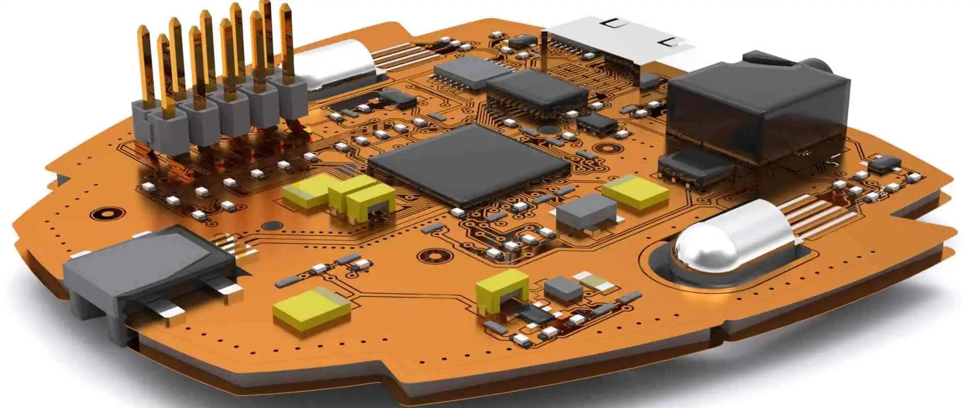
The embedded system is a small-scale computer developed for a particular function. It typically contains a microcontroller or microprocessor, the integrated circuit comprising memory, processor, & I/O peripherals on a single chip. 

The essential characteristic of the embedded system is its ability to execute digital processing. This sets it apart from virtual hardware devices that solely comprise circuitry and perhaps a battery. 

Embedded systems frequently feature sensors that enable them to monitor environmental variables. 

Difference between IoT and Embedded IoT

While an embedded system may not necessarily possess internet connectivity, an IoT(internet of things)embedded system does. The distinction between an embedded system and IoT is that an embedded system can be part of IoT. Embedded systems predating IoT did not have internet connectivity, making IoT(Internet of things) embedded systems typically inclusive of a wider variety of appliances and use cases.

What is an embedded system in IoT?

An IoT(Internet of things) embedded system is an embedded system with an internet connection. Another term for an IoT(Internet of things) embedded system is the “smart” application. A device does not require a touchscreen or keyboard to qualify as an IoT(Internet of things) embedded system, although such peripherals can be added.ย 

Types of Embedded IoT

FULL PCB MANUFACTURING Quote

An IoT-embedded system requires software to execute its intended purpose, which can take the form of either firmware /an embedded operating system. The software serves as the enabling factor for the IoT (Internet of things) embedded system to establish communication with other IoT-embedded devices.

In embedded systems, the phrases “embedded devices” and “embedded systems” are often used interchangeably, but embedded devices are typically components of a more extensive embedded system geared toward IoT applications. To distinguish between the two, an embedded device is a specialized piece of hardware designed to fulfill a singular or limited set of functions. These Single Purpose Appliances or Dedicated Devices are part of IoT(Internet of things) embedded systems crafted to execute a specific program or task unique to a specific business. 

Instances of IoT(Internet of things) embedded systems that are designed for a sole function include:

  • Kiosk devices
  • POS Solutions
  • Self-checkout systems

IoT embedded systems are extensively utilized in various industries, including retail, automotive, consumer products, healthcare, and others.

The contrast between IoT & Embedded IoT systems

In a single word, the disparity between IoT & embedded systems is “connectivity.” An embedded system can include a pacemaker, for instance, but when the device is enabled to communicate with the external environment, such as transmitting heart rate data to the central database, it transforms into an IoT(consumer products) embedded system

Another contrast between the embedded system & IoT(Internet of Things) is that IoT pertains to a group of devices that characterize the newly interconnected world. In contrast, the embedded system pertains mainly to the hardware employed in these applications.ย 

The primary differentiation between the embedded operating system & IoT is that the Internet of Things (IoT) operating system must facilitate connectivity. The capacity for networking IoT embedded system appliances is what sets them apart from regular embedded systems. 

Each IoT application involves the embedded system as an integral component, which is why it is called an IoT embedded system. The embedded system is created initially, and then features are added to transform it into an Internet of Things (IoT) device. 

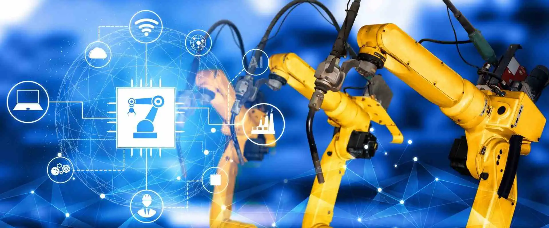
Embedded systems, such as robotic systems in manufacturing/data warehouses, can be highly complex in their own right. However, unless the application can communicate & establish connectivity with other IoT (Internet of Things) embedded systems, its role as a standard embedded system will be limited to its sole intended purpose.

The difference between an embedded system & the IoT embedded system lies solely in its capability to communicate.

The importance of Embedded IoT

To better understand the difference between an embedded system and IoT, it could be helpful to examine some real-world use cases. Here are a few examples that further clarify the contrast between an IOT and an embedded system.

To comprehend the contrast between an IOT and an embedded operating system, it is essential to note that both IoT(Internet of Things) embedded system appliances and non-IoT embedded system appliances rely on some form of software to function, whether it is firmware, bootloaders, drivers, or a comprehensive embedded operating system.

Merely being an IoT( Internet of Things) embedded system does not necessarily require a complete operating system, though it is typically the case. Appropriate Rating systems are appropriate for use in some embedded systems, such as Linux / Android.

By installing specifically modified versions of Android on the Internet of Things( IoT )embedded system, the appliance will be capable of:

  • Obtain OTA updates
  • Enjoy the benefits of Mobile Device Management, such as remotely managing an IoT( Internet of Things) embedded system. 

Android is a suitable operating system for IoT( Internet of Things) embedded systems. In addition, the introduction of the Raspberry Pi has made mass production of IoT( Internet of Things) embedded systems much more accessible, particularly after the release of its Generation 3 models that include built-in Bluetooth & WiFi connectivity. By installing Android on your Raspberry Pi 3 B+, the IoT(Internet of Things) embedded system can access Raspberry Pi Fleet Management features (like MDM) mentioned earlier.

Top Benefits and Characteristics IoT Industry 4.0

Smart Manufacturing IoT

The industry of manufacturing is gaining rapid popularity due to using advanced equipment and technologies like Machine Learning, the Internet of Things, and Artificial Intelligence. Digital advancement has remarkably enhanced the productโ€™s quality and significantly reduced the runtime of machines and processes. However, the industry of automation and the IoT is playing a significant part in this method.

The Industrial IoT has brought immense changes and transformations recently with its great benefits in the applications. It hugely contributes to the improvement of work efficiency and workflow within the factories through real-time management and controlling the process and assets altogether. The benefits that IIoT brings to us could be used significantly to make the industry better.

The benefits or opportunities that IIoT brings include Process Optimization, Automation In Factories, Performance Monitoring, and Intelligent Manufacturing.

IoT Industry 4.0

Industry 4.0 is an industrial revolution. Its main aim is to make the industry smarter by using advanced IoT technologies like automation, interconnectivity, exchange, and data monitoring in real time. Industry 4.0 is fully devoted to customers, doing its best to help the manufacturers in providing quality customer services and experience. The customer-devoted strategy of IIoT or Industry 4.0 covers product sales, product visioning, assembly, service management, and manufacturing. However, IoT plays a vital role by constantly helping the manufacturer with the needs and demands of the customers.

Evolution of IoT Industry 4.0

Industrial-IoT-Devices

IoT is the sole reason for the rapid development of Industry 4.0. Industry 4.0 is responsible for making connected everything within a shared network and allows the automation process of all operations, which reduces the effort and time of human resources. Data monitoring in real-time improves the process of decision-making while predictability protects the industry from future dangerous events and supports asset management for workability in the future.

The major stages of Industry 4.0 and IoT evolution includes generating insights, connecting things, innovation, and optimizing process and operations.

The main aim of IoT is to make things way smarter and internet connective no matter if it is home, office, building, hospital, or industry. While Industry 4.0 specializes in Augmented Reality, Cybersecurity, Digital Twin, Autonomous Robots, Connected devices, Big Data, Heavy machinery, and Cloud Computing. However, the primary points of IoT and Industry 4.0 are Heavy machinery, Smart plant grids, and Connected Devices. IoT leads towards the excellence of manufacturing by taking crucial and essential parts in almost all activities of industry and enhancing its efficiency. IoT technology is ideal for industries as it provides beneficial results by combining operational technology and information technology for operations and processes.

From Stream To Sensor: IoT Industry 4.0

FULL PCB MANUFACTURING Quote

ยท First Industrial Revolution:

The first massive industrial revolution came in Britain in the 18th century. It was the time when it helped in mass production with the help of steam and power rather than using animal and human power. However, the products are manufactured by machines instead of manually by human hands.

ยท Second Industrial Revolution:

The second wave of the industrial revolution hit after a century. It introduces oil usage, assembly lines, and electric and gas power. Other than these phenomenal power sources, other advanced ease of communication were also introduced, like the telegraph and telephone, which helped in mass production and automation of manufacturing techniques to some extent.

ยท Third Industrial Revolution:

In the 20th century, the third industrial revolution hit, which brought data analysis, advanced telecommunications, and computers into the manufacturing process. The process of digitization has been introduced in the factories by integrating PLCs into manufacturing machines to advance the automation process and transfer data here and there.

ยท Fourth Industrial Revolution:

Currently, we are living in a fourth revolutionary era of industries which is also called Industry 4.0. It enables automation of the process of manufacturing, making factories and machines smart, and analyzing the production data, which helps in producing quality and efficient products. With industry 4.0, flexibility is enhanced, which lets manufacturers provide customized products meeting the demands of customers. This leads to efficiency in many sectors. Moreover, combining the operational data of different floors in one system enables the smart factory to make better decisions.

Characteristics Of an IoT Industry 4.0

Data Analysis

Interconnected machinery and integrated sensors generate a considerable amount of information for manufacturing industries. Data analytics aids manufacturers in analyzing historical trends, recognizing patterns, and making reasonable decisions. Smart factories also take data from other areas of industry and their ecosystem of distributors and suppliers to produce deeper insights. By taking a look at data collected through human resources, warehousing, or sales, manufacturers can make decisions about productions solely based on personnel and sales margins. An exclusive representation of operational digitization can be made as a digital twin.

The Benefits Of IoT Industry 4.0

There are various ways of integrating IoT into factories and their manufacturing process. Here are some beneficial points of integrating IoT in the factories.

ยท Data collection & automation

Automation and Data collection are one of the best features of integrating IoT in the manufacturing factory. IoT gathers data on all aspects of the manufacturing process and provides remote commands. This helps in enhancing production and its efficiency and increases the output while reducing effort, time, and expense.

One best example of IoT is integrating internet connection ability in the PLCs. This analyzes the data of the manufacturing process thoroughly and immediately reports to the producer if anything goes wrong. They also give permission to change parameters remotely at any time, which helps managers to correct the inefficient component in the assembly.

The workflow of the customized motorbike of Harley-Davidson is a real model of how the Internet of Things has developed manufacturing efficiency. In 2016, the manufacturers of this motorbike installed IoT devices and sensors in the machines of their factories to identify the speed limit of work. Well, they gathered data that reduced the time of manufacturing by up to 6 hours. And they saved up to $200 million in this process.

ยท Data Security

The primary security problem in the management of data for businesses is human error. BakerHostetler’s report back in 2018 shows that humans were the main reason for most cybersecurity incidents that they had managed. Among those incidents, the ratio of cases that were caused by employees was 17% which led to data breaches.

However, integrating IoT in the management of business helps in improving the management and reduces the number of humans managing the data manually. This is because IoT allows one to monitor, send or receive reports remotely through an automatic system without going through reading all emails all day.

In simple words, IoT reduces the time human users interact with data which automatically reduces the risk of human errors.

ยท Predictive Maintenance

The runtime of one hour of manufacturing machines costs millions. In the manual process of manufacturing, staff members have to look around all the time in search of whether the machine is working properly or not. If not, then find the solution to it, which also adds up to the expense.

IoT applications significantly reduce the downtime of machines by providing predictive maintenance. With smart sensors and AI integrated into all machines, manufacturers can closely look at the health and stability of the machines. It notifies the team of maintenance right away if there is a slight fault that occurs before getting things any worse. This not only helps in reducing the downtime of the machine but also makes it stay longer.

Predictive maintenance helps manufacturers in saving a lot. According to the U.S. Department of powerโ€™s data, enforcing predictive measures leads to a reduction of breakdowns by up to 70-75%, maintenance cost by up to 25-30%, downtime by up to 35-45%, and return the investment in ten folds.

ยท Workplace Safety

By using unique and advanced technologies, IoT also improves the security level at the workplace. Smart sensors integrated at every manufacturing floor provide the manufacturer with constant feedback with the latest details and information. If any incident happens, the alarm system alerts the facility while stopping the machine and dispatches the maintenance team to reduce the risk of injuries.

Wearable devices with IoT also protect the workers. For instance, a smart band consists of sensors for pressures that can warn the workers of areas with a loud noise that can damage hearing. Same as augmented reality spectacles help in analyzing areas that could be dangerous and hazardous for workers.

Smart, hard hats are one of the live examples of this. It is a product of two companies’ collaboration. These hardhats with various features can sense the location of the user, humidity, temperature, and heart rate. These hardhats warn the workers if their vitals get low and if they are near getting heatstroke. Moreover, it also warns users of dangerous areas by vibrating or sound emitting.

IoT Industry 4.0 is Not The Future; It Is The Present

IoT devices are already getting popular among manufacturers, and they will not stop here but grow faster. As it directly benefits efficiency, cost, and risk management, it would be a loss if any manufacturer would not have IIoT in their factories.

How Is A 2.2K Resistor Different from Other Resistors?

Resistor color

2.2K ohms resistors are very popular in the electronic industry. These resistors are also known as axial-lead resistors. You can confuse these resistors with other resistors due to your less knowledge. They have unique color codes, so it is easy to recognize them. Start from the basics for a better understanding of the 2.2K resistor.

What Is a Resistor?

 Resistor is an important part of any electronic circuit. It has different uses. Its most important functions are to lower the current flow and divide the voltages. It can also block the transmission signal also. Resistors are also different types. Every resistor has different resistance and serves a different purpose. Thatโ€™s why you cannot put a specific resistor in every circuit design.

What Is A 2.2K Resistor?

‘K’ stands for one thousand ohms. So, 2.2K resistor means it has a value of 2.2000 ohms. It can also be said to have a value of 2.2K. A 2.2K resistor has multiple uses. It is a passive device, but it allows designers to design the circuit as they want to. In simple words, it gives you control over currents and voltages.

How To Recognize The 2.2K Ohms Resistors?

FULL PCB MANUFACTURING Quote

Each color band on the resistor has a specific meaning. It has at least two digit bands, one multiplier band, and one tolerance. This is the structure of a four-band resistor color code.

If your 2.2K resistor is a 4-band resistor, then the first three bands are normally red in color and give normal values, while the 4th band is the tolerance band of the resistor. Tolerance bands have different tolerance according to the color code.

 Similarly, five and six-band 2.2K resistors are also available in the market. Six band resistors have one extra band, which is the temperature coefficient. This is an indication of how sensitive the resistor is to temperature changes.

How To Read the Four-Band 2.2K Resistor?

 Many people find it difficult to read the color code of the resistor. They don’t understand the values of each band. Color lines on the resistor are not for decoration purposes. Every resort has a significant color code.

The color code of the 2.2K resistor is Red-Red-Red-Gold. Resistor color codes consist of digits followed by a multiplier and a tolerance value. Four-band resistors have two bands for digits. Each band on the resistor has a specific value. The first two bands are red in color. Therefore the digits from band one and band two are 2 and 2. Band Three is a Multiplier band. It takes the digits and multiplies them by a value of this band. Band Four is the Tolerance band. It gives the value of the tolerance for the resistor. So it’s not hard to read the color code of any resistor.

Advantages Of 2.2K Ohm Resistor

Resistor Wattage

The following are some advantages of the 2.2K resistor.

ยท Better Temperature Stability

Temperature stability is necessary for the proper and efficient working of resistors. 2.2K resistors have better temperature stability, so they work well even in harsh environments.

ยท Lower Noise

Sometimes noise becomes a problem when dealing with resistors. 2.2K resistor is the solution to this problem, so go with it. If you want to lower the noise in the circuit, the 2.2K resistor is ideal.

ยท Better For High Radiofrequency Applications

Sometimes opting for a good resistor becomes a problem when you are working with a complicated circuit. 2.2K resistors go well in high-frequency devices and applications. These resistors serve their purpose well. So if you are into high-frequency devices, then you must go for a 2.2K resistor.

ยท Low Cost and Easy Availability

 Cost is a matter of concern in circuit making. Low Cost is the advantage of a 2.2K resistor. The 2.2K resistor is one of the most affordable resistors available in the market. It is an ideal choice for budget-conscious electronics projects. It is also very easy to find, as it is widely available from many different suppliers. This makes it a great option for those needing to purchase bulk resistors. It is also a great choice for many newbies in the electronic world.

ยท Ensures A High Degree of Safety And Reliability

The 2.2K resistor helps to protect other components in the circuit from damage due to excessive current. This makes it an ideal choice for projects that require a high degree of safety and reliability.

Tips For Using 2.2K Resistors in Circuits

 The following tips will help you to design the best circuits while using a 2.2K resistor.

  • Verify the resistor’s tolerance before putting it into the circuit. Make sure the resistor’s tolerance is acceptable for your circuit’s requirements. Sometimes you use a very high resistance value resistor, and it ruins your circuit.
  • Environmental changes can affect the functions of resistors. So whenever you put the 2.2K resistor in the circuit, then keep the environmental factors in mind. Things like high heat, humidity, or other environmental conditions have effects on performance. Many people neglect environmental factors. In my opinion, humidity, and heat are both culprits in most circuit failures.
  • Always buy 2.2K resistors and other electronic components from a reliable vendor. If you don’t consider it, then low-quality resistors can affect the proper functioning of the circuit. A low-quality resistor doesn’t provide you with the proper results. It can’t serve

Conclusion

A 2.2K resistor is a common component in electronic circuits, and it has many advantages over other resistors. The 2.2K resistor is an excellent choice for electronics projects due to its low cost and high resistance. It is easy to find and fits into tight spaces. That’s why it is ideal for budget-conscious projects. Additionally, its high resistance helps to protect other components in the circuit, that’s why the 2.2K resistor is an excellent choice for many different types of electronics projects.

What is SIM800C ARDUINO? A complete Guide in Electronics

esp32 sim800c

The world of technology has been loaded with the field of IoT or the Internet of things. IoT has changed our way of seeing the world and work ethics. It’s been a part of every technology around us including consumer electronics and industrial devices.

The SIM800 from both Arduino and SimCom has gained immense popularity recently because of the great support from the community of developers and technicians. 

Connecting to the Internet, sending emails, texting, and calling all occurred through cellular communication. This cellular communication device is known as SIM800. This module basically functions as a smartphone but needs an external connection to work properly. The SIM800 possesses so many qualities and features. 

SIM800 helps you in creating innovative projects if it is connected to Arduino. SIM800 is not only good at making projects but is also a very viable and affordable choice to use as a communication module in various types of devices.

Consideration:

sim800c arduino

The following mentioned benefits and disadvantages help you in understanding whether it is the best option to choose for the project or not.

Pros:

  1. The biggest pro of SIM800 is that it is supported and recommended by many experienced and skilled technicians and developers.
  2. It has amazing features for texting, calling, and internet access.
  3. It comes in small sizes which makes it perfect to use in consumer devices especially wearable and portable ones. 
  4. It is affordable and cheap, especially when it is bought from Chinese manufacturers.
  5. Many manufacturers like SimCom also provide SIM800 with other communication modules. Built-in GPS is one of those amazing features.

Cons:

  1. One of the biggest drawbacks is that it only comes with a limited 2G data speed. Moreover, the GPS has also been phased out many times in many areas.
  2. Regardless of being small, affordable, and high-performance, it’s only used for cellular modules generally.

Warning:

The GSM and GPS cellular module in SIM800 only works in specific phases and it is phased out in most regions which is why it is especially not a recommended choice for modern designs.

Programming & Prototyping for SIM800C ARDUINO

FULL PCB MANUFACTURING Quote

Basic Connections

The connection between SIM800 and Arduino for general communication links is quite simple. You just need three lines between Arduino and SIM800. These contain receive and send lines of ground UART.

After that, put the SIM card inside the SIM800 module. Connect the RX and TX SIM800 with D7 and D8 Arduino respectively. These provide a communication link between different modules and are called serial UART links or connections. 

Also always ensure that the SIM800 sending pin connects with the Arduino receiver pin and the SIM800 receiving pin connects with Arduino sending pin. 

Arduino uses 5V while SIM800 is not able to tolerate 5V which is why the level logic it uses is 3.3V. This shows that the D7 Arduino signal has to step down to a SIM800 logic level of 3.3V so that it wonโ€™t get damaged. Various methods are available but using a resistor divider is one of the simplest and easiest ways. 

After that link, the antenna with the mini socket is placed in the top left area of SIM800.

Power Supply For SIM800C ARDUINO

3.7V is the standardized power supply to the SIM800 among various cellular modules. People might consider using the 3.3V and 5V supply which is really not recommended. The SIM800โ€™s tolerance of power supply is between 3.4 and 4.3 volts. Therefore, using 5 voltage power supply could damage the module while 3.3-voltage is not considered enough for a reliable connection. 

That is why an external polymer battery with a voltage of 3.7V is utilized as an external power source. Generally, for the best result, a decoupling power-generating circuit is put into the supply of input. 

ยท Serial Monitor:

A serial monitor provides interference with Arduino while communicating with SIM800. It is also used for checking the current state of the appliance. Moreover, it is also used to send commands for communicating with Arduino.

ยท Simple Serial communication:

The code is used to create a communication link between Arduino and SIM800. First of all, a set of pins generates a simple serial communication connection between both devices. Then set the rate of buad up to 9600.

During the looping of code, SIM800 constantly waits to get any input signals from the serial monitor. It then sends the input signals to SIM800 using the D7 pin. It also constantly reads the pin D8 in case the SIM800 sends any responses back.

Once the Arduino is connected to the device like a PC, the setup is completed. Compile serial communication code and then upload it on Arduino. Since the basic serial connection is established, there is also another way to communicate with SIM800 through the monitor by transferring AT commands. AT command is a type of command key specially created to perform the desired operations on SIM800. The code is sent to Arduino which relays the message to SIM800 to perform.

โ€œATโ€ is one of the basic commands anyone can use. When โ€œATโ€ is typed on the serial monitor โ€œATโ€ comes in the response. This ensures that Arduino has a perfect communication link with the SIM800 module.

ยท Downloading Web Page:

The SIM800 module has a remarkable ability to download web pages from the Internet. This can easily be done by putting an AT command on the serial monitor.

First of all, ensure the quality of signals. Since SIM800 is an old version so there might be a chance of not getting proper internet signals. Therefore check the quality of the signal by putting the command โ€œAT+CSQโ€. This is not used to create a strong internet connection. However, it might help in monitoring the level of signals during the debugging process.

After establishing and checking the internet connection then comes up creating a web session by setting an environment of the browser. First of all, the HTTP setting is being placed. Then put the URL of the website you want to download. The command relays to the SIM800 module and makes it download the website page. Once all the data on the web page is downloaded. You can easily access all the content by using a serial monitor.

What Else Can You Do With The SIM800C ARDUINO?

sim800c arduino board

The SIM800 module can easily be integrated into consumer, miniature, and portable devices, especially wearable gadgets. SIM800 module and the Arduino are also widely used in making automation systems for homes, GPS trackers, and wireless sensor remotes. 

ยท Low-cost Weather Forecast

One of the simplest uses of the SIM800 module and Arduino is creating a weather forecasting gadget, especially for farmers at low cost. This project used colors to provide weather forecasts for almost 10 days. 

The device is designed to locate the user’s current location and then download the weather details from a famous weather forecasting platform called Weather Underground. One of the biggest features of the SIM800 module is to identify the current location of this device. It does not give an as accurate location as GPS can give but for such a simple device, a rough estimate would be enough.

ยท GSM Antenna

Antenna can be added to the device and product in two ways by utilizing the SIM800 module. It can be added either by using an SMA connector or a mini Radio-frequency coax connector. The Radio-Frequency interface contains 50 ohms impedance. However, this impedance also matches the trace resistance of the antenna. 

Designing Radio-Frequency traces for the antenna of the SIM800 module is a quite complex process. Therefore, for design, you need expert guidance and advice so that there wonโ€™t be any mistakes. For better results and avoid unwanted mistakes then follow the design guidelines of the manufacturer.

Conclusion

The SIM800 module is an ideal choice for creating a 2G cellular communication link in consumer devices or the projectsโ€™ products. It is small, affordable, easy to handle, cheaper, and has a friendly user interface through the monitor, and commanding ability makes it ideal among many developers and manufacturers. Since it is ideal for many reasons, it gained popularity and is supported by various technicians and developers. It is widely available around the market and can easily be found. 

Everything You Should Know About 1.2K Resistor

2.5K Resistor

1.2K resistor is a popular resistor in the electric world. It is part of many delicate circuits. It is essential for the proper functioning of the circuit. A layman may consider it a passive component in the circuit, but it can do surprising things. Let’s dig deeper to know more about resistors, especially 1.2K resistors.

What Is A 1.2K Resistor?

A 1.2K resistor is a resistor with a resistance of 1.2-kilo ohms. If you are a layman, then you may get confused. In simple words, when an electric current flows through the resistor, it will come across a resistance of 1.2 thousand ohms. The unit “k” represents the “kilo,” which means thousand. The symbol “ฮฉ” represents the unit of electrical resistance, called “ohm.” What are the resistors?

Resistors are electronic components. Many of you may familiar with them. Resistors are part of circuits for different purposes. For example, to limit the current flow, voltage divider resistors are your best friends. The resistance value is measured in ohms, kilohms, or megohms. Different resistors have different values. For example, if you are using a 1.2K resistor in the circuit. Then electric current encounters the 1.2-kilo ohms resistance. As a result, it can affect the behavior of the circuit.

What Are the Popular Uses Of 1.2K Resistors?

Resistor color
  • Like other resistors, 1.2K resistors also have a wide range of uses in electronic devices and circuits. Their uses depend upon the specific application and requirements. The following are some examples of devices and circuits where a 1.2K resistor is a good choice.
  • In a voltage divider circuit, a 1.2K resistor can be used to divide the voltage between two points in the circuit. For example, it can be used to create a voltage reference for an analog-to-digital converter.
  • In a circuit that includes an LED, a 1.2K resistor is a good choice. Its limits the flow of current
  • In an amplifier circuit, a 1.2K resistor can do wonders. It works as part of a biasing network to set the operating point of the amplifier. A 1.2K resistor can be used as part of a feedback network to stabilize the gain of the amplifier. The feedback network has resistors. It helps to reduce distortion and improve the frequency response of the amplifier.
  • In digital circuits, a 1.2K resistor serves best and fulfills the requirements.

What Is The Color Code Of The 1.2K Resistor?

A 1.2K resistor has a color code of brown, red, red, and gold. Here’s how to interpret the color code:

The first band is brown, which represents the number 1. The second band is red, which represents the number 2. The third band is also red, which means there is an additional zero that needs to be added to the number. So the actual value of the resistor is 12 with one zero added, which is 1.2 in scientific notation.

The fourth band is gold, which represents the tolerance of the resistor. Therefore, a 1.2K resistor with a tolerance of +/- 5 percent would have the color code of brown, red, red, and gold.

 Things To Keep In Mind While Using A 1.2K Resistor In The Circuit

FULL PCB MANUFACTURING Quote

 Following are some important things to keep in mind while using a 1.2K resistor in a circuit:

  • Make sure the power rating of the 1.2K resistor is sufficient for the circuit. Exceeding the power rating can cause the resistor to overheat and possibly fail.
  • Verify the resistor’s tolerance: Resistors have a tolerance, which specifies how close the actual resistance value can be to the nominal resistance value. Make sure the resistor’s tolerance is acceptable for your circuit’s requirements.
  • Make sure the resistor is installed in the correct orientation. Otherwise, you may encounter unexpected results.
  • Make sure the resistor is not exposed to any high temperatures, humidity, or other environmental conditions.  

Frequently Asked Questions?

What Is the Difference Between 1.2 And 2.1 K Resistors?

 Many people confuse both of these two resistors. A person who has good knowledge may know the difference well. 2.1 K resistor has more resistance compared to the 1.2K resistance.

A 1.2K resistor has a resistance of 1.2Kilo-ohms, while a 2.1 K resistor has a resistance of 2.1 Kilo-ohms. Therefore, a 2.1 K resistor will limit the flow of electrical current in a circuit more than a 1.2K resistor.

Which Resistor Is Best Between 1.2 And 2.1 K Resistors?

The choice of which resistor to use in a circuit depends on the specific requirements of the circuit, such as the desired current flow and voltage drop.

If the circuit requires a higher resistance, then the 2.1 Kฮฉ resistors would be the better choice. On the other hand, if the circuit requires a lower resistance, then the 1.2Kฮฉ resistor would be the better choice.

It is important to note that the choice of resistor also depends on other factors, such as the power rating of the resistor. ย Tolerance and the temperature coefficient are also important. Therefore, when selecting a resistor, it is important to consider all of these factors. As a result, you can choose the resistor that best meets your needs

From Where I Can Buy Online 1.2k Resistors in Bulk?

 There are several vendors on many online platforms. They are selling electronic components, including resistors, in bulk. Read the reviews regarding your selected vendors and then go for purchase. If reviews and ratings are good, then you must go for them. If you find some negative reviews, then consider it a red flag. A reliable vendor will provide you best quality electronic components.

Conclusion

The 1.2K resistor is an important part of electronic circuits. That’s why it has several uses, such as a current limiter, a voltage divider, and as part of feedback networks. You cannot complete your circuit without a resistor. Its importance lies in its ability to control the flow of current and voltage in a circuit. That’s why it is essential for a proper circuit operation.

how to improve fm signal on radio with a single wire antenna

NFC Antenna

Radios can be found in various locations, including shops, homes, cars, and public spaces. Their user-friendly design and cost-effectiveness have made them a popular choice among many individuals. Nevertheless, there are a few issues that one might encounter while utilizing them.

A common problem while using a radio outside the home or in an area surrounded by tall buildings is poor signal quality. This is due to the limited range of radio frequencies, typically between 400 to 470 MHz, divided into various sub-bands to meet the user’s requirements.

If you are experiencing weak FM signal reception, check out this video to learn how to enhance the signal using a simple single-element antenna:

These frequencies fall under the UHF spectrum, allowing for up to twenty various radio frequencies to coexist in a similar location. As buildings are generally not too tall, they don’t significantly obstruct the signal.

The change in signal strength may not be noticeable when you are outside. However, when you enter areas surrounded by tall buildings, you may experience a decrease in signal quality as these buildings act as a barrier to the signal.

UHF (Ultra High Frequency)frequencies are commonly utilized for handheld radios due to their wider bandwidth compared to the frequencies utilized for television or radio broadcasting. However, the major drawback of using UHF is known as LOS propagation.

The signal takes a direct route instead of bouncing off objects, which is desirable for clear handheld reception. However, this can pose an issue when using the device in outdoor settings or locations surrounded by tall structures.

UHF frequencies cannot readily penetrate objects, but they can induce objects to redirect their signals. As a result, instead of following a direct route from one radio wave to another, signals are redirected by objects, leading to a distorted signal waveform.

Radio reception becomes more challenging when using the device outdoors or inside a vehicle. The signal stability is impacted due to difficulties in maintaining a constant signal.

Steps to Improve FM Signal with Only Single Wire Antenna

L Band Patch Antenna

To enhance the signal of an FM radio with a single-wire antenna, specific measures must be taken. These steps are standard, as with specific type of antenna tend to exhibit similar behavior. 

Here are the steps:

1st Step

To begin, you need to detach the Broadcasting antenna. Detaching the aerial from the means of communication will enable us to identify the arrangement of the antenna and cables so that we can assess if any modifications or adjustments are required for the system. Alternatively, it can help us determine if there’s any physical damage-related issue. Ensure to carefully remove the aerial by loosening all the screws that secure it and unplugging the antenna connector. Also, extend the antenna to its full-length capacity.

2nd Step

In the 2nd step, after removing the antenna, reattach it to the radio and turn it on. Tune in to the desired channel. Next, lift the antenna upward until it extends to its maximum height. Adjust the antenna sideways or at different angles to improve sound quality. Repeat this process until no interference is heard, which signifies excellent radio reception.

3rd Step

To ensure the radio connection stays strong, you can secure the end of the antenna with tape. Initially, you might experience a reduction in signal strength when the antenna is not being held. To combat this, keep moving the antenna until the sound is clear and the signal quality is good. Another method of testing the quality of the signal is to move around the radio and look for any signal interference. If you detect any interference while walking close to the radio, you may want to consider making modifications/ adjustments to the systems. If the radio signals are not disturbed, then the settings of the current are good to go

Improve Signals with Obstruction

FULL PCB MANUFACTURING Quote

The fluency of the radio signal can be impacted by many obstacles & materials in different locations. To enhance FM radio signals, it’s essential to follow specific recommendations. One of the critical factors that significantly impact the radio signal in buildings is the materials used in walls/ceilings, such as steel.

Recommendations:

  1. The radio should be relocated to a location with fewer obstacles impeding signal reception. In various buildings, certain materials used in walls, such as steel and iron, can hinder the flow of the radio signal. Besides the materials, other physical characteristics of the building, like the height of the building, and the thickness of the walls, also affect radio signal receptivity. The best places to locate the FM radio within a building are windows.
  2. To find out which way the antenna should face, you can try listening to a channel and see how clear the sound is. Some radios at home don’t have a big antenna and use a skinny wire instead. The power cord can also work as an antenna in some situations.
  3. If your current antenna isn’t giving you a good signal, you can add a new one to the radio system. You can use dipole antennas or the old-fashioned “rabbit ear” antennas on TV sets. Connecting a new antenna to the radio will make the FM signal stronger. You can attach the U-hooks to the screw terminals on the radio antenna. Finally, find a spot for the new antenna to get the FM signals.
  4. To improve the sound of the FM radio, switch it from “stereo” to “mono.” FM radio stations usually broadcast in stereo mode, but it can be challenging for the radio to receive a clear signal. When you use mono mode, it gets rid of the two channels, but it also makes the signal less fuzzy and with less static, which leads to a more robust sound.
  5. If the above steps don’t make your FM radio signal more precise, you may consider installing an outdoor antenna. This kind of antenna can help the signal flow without being blocked by buildings. You can buy outdoor antennas from electronics stores, just like the ones people used to have on their roofs for their TV. These antennas can significantly improve FM radio signal reception. If you get an outdoor antenna, it’s best to put it as high up as possible and connect it to the radio using a coaxial cable.

Boosting the Signals

After you adjust the antenna, you can make the signals stronger. This is what you do:

  • To get better radio signals, try to make the power cord for the radio as straight as you can. This usually helps make the signals stronger.
  • Change the audio from stereo to single sound (Mono).
  • Slowly extend the antenna and move it around to different positions. This will help you get the best signal and improve reception.
  • To make the radio work better, place it near a window. This will help it receive signals better and reduce obstacles that block the signal. Remember that the signals come from outside where the tower.
  • If you want even better reception, you can get a special dipole antenna. You can find these at an electronics store or hardware store. Please attach it to the FM input on your radio, which will help improve the radio signal.
  • To use a dipole antenna with your radio, connect it to the FM input and adjust the wire to find different stations.
  • If you live far from a transmitting tower and want better reception, consider installing an outdoor antenna outside your house.
  • Once the outdoor antenna is set up, connect the wire to the input jack on your radio. Make sure the antenna is securely attached to the roof and positioned level, not tilted.

Advantages

FM amplifiers can help make your car radio sound better. They’re quick and easy to install and only need a simple antenna. You’ll see an improvement in sound right away, and since they do not take up much room, they’re a great solution.

Conclusion

By following these tips, we can make our radio equipment work better. This way, we can always listen to our favorite stations and stay updated on important news & information, especially in an emergency.

But by using the easy tips in this blog, you can make your radio’s FM signal better with just a simple antenna. Do you’ve any problems or need help? Ask a professional for advice.

SolidWorks PCB Services, what is it all about?

SolidWorks PCB Services

Printed Circuit boards have become the main components of the electrical gadget we utilize to undertake our day-to-day activities. Therefore, if you have used an electrical device, for example, a phone, a watch, or even a laptop, you have utilized a PCB. However, most of the time, we only experience the efficiency and the optimized performance that comes with PCBs, not the struggle that goes into manufacturing these components.

Producing a Printed circuit board requires technicians to utilize complex processes that use a lot of resources and energy. However, out of the many processes that lead to the manufacturing of a PCB, the stage tends to be more crucial than the restโ€”the Designing stage. However, due to its complexity, manufacturers have developed impeccable software programs to help PCB designers. One of these incredible software programs is SolidWorks PCB. SolidWorks was initially created as a modern-era, revolutionary tech for printed circuit board design integration with three-dimensional mechanical design ENV. However, after creation, this software program offers more than just this single feature. So what exactly does the SolidWorks Printed Circuit Board Software have to offer? And why should you consider using it over other competitive software programs?

Printed Circuit Boards in a Nutshell

layout
layout

Printed circuit boards, or simply PCBs, are electronic circuits we use in electronic devices to offer electrical connectivity and mechanical support to electrical components, for example, ICs. We produce PCBs by combining various sheets of components that are non-conductive, for example, plastic or fiberglass, that can easily hold the copper circuitry.

We also refer to PCBs as Etched Wiring Boards (EWB) or Printed Wiring Boards (PWB).

A printed circuit board functions on the CU or copper circuit/assembly/films that are carefully embedded inside the non-conducive materials to offer a pathway that effectively transmits electrical current. Printed Circuit Boards can hold multiple electrical components soldered onto them without using cables. The elimination of cabling makes electrical devices that run on PCBs lighter. Moreover, it eliminates the issues that come with using cables on electrical appliances, such as higher risks of short circuits.

Printed circuit boards are present in almost every computing device and electronic gadget out there, including:

  • Graphics cards
  • Network cards
  • Motherboards
  • The internal circuitry of CD-ROM/Hard Drives

Due to their application areas, you must carefully manufacture printed circuit boards. That is because messing up might make the circuit board fail, ultimately leading to the gadget failing. And considering that circuit boards operate in critical machines such as life support machines in the medical industry, this is not something that you would want to happen.

SolidWorks Printed Circuit Board Services

FULL PCB MANUFACTURING Quote

SolidWorks printed circuit board, formerly PCBWorks, is a printed circuit board (PCB) designing tool that PCB designers integrate into the popular SolidWorks three-dimensional design software. To install this program, utilize the SolidWorks Installation manager, which installs this program as an individual installation.

Electrical engineers utilizing SolidWorks PCB can easily alter the design of a PCB and then push the alterations to a repository. Moreover, mechanical engineers using this software can also easily access the altered PCB design from the prior saved repository. After accessing this design, they can analyze any modifications made, make additional alterations, and then push the new design back to its repository, where electrical engineers can access it to make more changes.

Through this collaboration, technicians can generate high-quality and optimized PCBs. Moreover, this collaboration ensures that designers catch errors in the early stages before they move the design to production.

However, to make this collaboration possible, you must install SolidWorks Printed Circuit Board Services, which effectively manages various repositories on shared servers. The SolidWorks PCB services program installs via the SolidWorks Installation manager. Hence, it doesn’t require you to purchase a new license to use this program. Moreover, this program includes databases for storing data and sync the alterations made by various mechanical and electrical engineers. It also includes MIIS or Microsoft Internet Info Services.

In various network ENVs, you install SolidWorks printed circuit board services on a shared server that doesn’t have the SolidWorks Programs installed. Moreover, you can also install this software with various SolidWorks Printed Circuit Board components on one machine.

To ensure its efficiency and effectiveness, you must have this software running 24/7. Moreover, you must ensure it has bidirectional, uninterrupted communication through virus scanners and firewalls with users running the SolidWorks program and the SolidWorks printed circuit board software.

Key Features of SolidWorks PCB

Altium Designer 20

MCAD/ECAD Project Collaboration Server

MCAD/ECAD collaboration servers help you facilitate the collaboration between the mechanical and electrical sides of the PCB designing project.

Moreover, these servers also help you link electrical data to the mechanical models of SolidWorks CAD. Combining this information in one place enables you to manage your project better. Moreover, it also ensures seamless synchronization of information, which is crucial when working with a team.

Parasolid Support

The SolidWorks PCB services program supports the native Parasolid SolidWorks file format, which ultimately widens the scope of this software application-wise. Moreover, using this software, you can easily link parasolid models for component bodies and enclosures and then view them in three dimensions to ensure the board you are designing fits mechanical enclosures perfectly.

Copper Analysis

You can quickly improve your design’s accuracy using SolidWorks CAD and SolidWorks PCB. Moreover, this software lets you send your PCB design to the SolidWorks CAD bearing Copper information. After processing, you get back a detailed mechanical, vibration, and thermal simulation, which helps you view your design from a new angle or perspective. Moreover, this simulation can help you identify and fix errors before you move your design to production. Doing so will make your design less prone to errors after production.

Conclusion

Printed Circuit boards are a crucial aspect of the electrical industry. They help manufacturers produce compact electrical gadgets that are powerful and efficient. However, to use these circuit boards, they have to manufacture them first. During the manufacturing process of PCBs, technicians have to start from the designing phase, which is crucial. That’s because any mess made during this stage is carried forward to the production stage. However, to avoid this, you should utilize the SolidWorks PCB services program. It lets you collaborate with mechanical and electrical engineers to help you generate an efficient and flawless PCB design.

Why the Voltage Divider Formula is Important

Voltage Divider Formula

Voltage divider formula is a complete yet user-friendly tool that enables you to assess the output signals (i.e. voltage) which is produced by one voltage divider, which is frequently used for voltage regulators.

Continue reading to find out what the voltage divider formula is, its basic calculator, and the way it applies to different equations for various types of voltage divider. Learn how this voltage divider formula and rule can be used to obtain a portion of the input voltage.

Consider the myriad ways the voltage divider is used in both simple and extremely complicated systems to further persuade yourself that the electronic circuits shouldn’t be anything to get concerned about.

What Does a Voltage Divider Mean?

The voltage divider can be described as a straightforward circuit that lowers voltage. It equally distributes its input voltage amongst some of the circuit’s components. Two resistors linked in series, and with input voltages applied across its resistor pair as well as the output voltages drawn from the point in between, are the best representation of the voltage divider.

It’s employed to generate various levels of voltage from a single source of voltage while maintaining a constant current for each component in series circuits.

Voltage Divider Formula and Calculator

Inductor voltage and current waveforms

The output voltages of the voltage divider always reduce its input voltage as well as the current that flows through a series network, which is determined by Ohm’s Law, (V=IR). The current between them is equal since this current is shared by both resistors. We can figure out the voltage that was lowered across the second resistor, with the help of this formula.

The voltage passing across many resistors connected in series having a DC source of voltage can be calculated using the voltage divider formula and calculator (can handle about 10 resistors).

Calculating the entire resistance of the whole circuit in series is how the voltage divider operates. Voltage divider formula is then applied, with Resistor 1 serving as the particular resistor which we are attempting to calculate the drop in voltage across is. For each resistor in voltage divider circuits, this calculation is repeated.

The higher the resistance values of the elements, the more voltage would be lost across them, according to Ohm’s law. Likewise, less voltage passes through resistors having lower values for resistance.

The VIN, input voltage, as well as resistor values, ranging between 1 and 10, must both be entered in order to utilize the voltage divider formula and calculator (to serve multiple resistors connected in series). Then, the user must click on “Calculate” button. Each resistor entered will have its voltage drop calculated and then automatically displayed. This voltage’s outcome is calculated in volts.

The voltage divider formula for a voltage divider circuit of two resistors is Vout=Vin(R2R1+R2), while for two resistors, it is VRx=Vin(Rx/RT).

What is the Rule for the Voltage Divider?

FULL PCB MANUFACTURING Quote

The idea behind the voltage dividers indicates that though this voltage is divided in some way across the series-connected parts, the current flowing through them remains constant. To determine the precise numbers for our circuit, you must use Ohm’s law. To start, we must make the following very important information:

The only composition that applies to DC circuits is RR composition. In these circumstances, any impedance can be regarded as wires having zero resistance, and capacitances function as a circuit’s gap, where they have an infinite resistance. The rule for voltage divider is valid for the highest value of potential difference for the remaining ones, which are all employed with AC circuits. Finding a phase shift to suit these voltages might be just as useful.

Voltage Ladder

The circuit known as the voltage ladder consists of many resistors connected in series having a voltage applied across the whole network of resistors. The voltage drop of every resistor in these networks is greater than that of the one preceding it.

The current remains constant across the entire ladder because the resistors are connected in series. Divide the entire voltage by total resistance to obtain its value. By multiplying the entire current by each resistor’s value, one may determine each resistor’s voltage drop. The total of voltages lost by every resistor between a node as well as ground can be used to define the voltage referred to ground at every given node.

Input Voltage and Voltage Drop

The output voltages and divided voltage throughout the circuit are both determined by the drop in voltage across R2. Two resistors are connected in series to provide a voltage divider that is referenced to the ground.

R1 as well as R2 are connected in series to form an input voltage, while R2 receives its output voltage. There is therefore nowhere else for the same amount of current which passes through every resistive component of circuits. Therefore, this delivers a voltage drop of IxR across every resistive element as a result.

We can use the voltage law of Kirchoff and Ohm’s Law in determining the drop in voltage across every resistor based on the current flowing across them after knowing the supply voltage.

What are the Applications of the Voltage Dividers?

Below are some of the uses for voltage dividers:

A potentiometer is a well-known device that utilizes the concept of the voltage divider. This component is also known as a rheostat.

Typically, they are made entirely of resistive parts. We can differentiate between digital as well as analog ones, but we can tune the resistance using extreme precision in either case. Slide pots, trim pots, and thumb pots are some most well-liked varieties of potentiometers, and they differ in size and construction. The sliding contact, which makes it possible to alter the resistance of the output, is the key component.

Equipment for measuring high voltage – This comes out that high voltages can be measured, despite the fact that direct measurements may be harmful to the instrument. In that situation, it is practical to drop the voltage onto a secure area using a voltage divider. It is preferable to utilize capacitive devices rather than resistive ones at really high voltages.

Locating an unidentified resistance:  If you just have the voltage source as well as another resistor having a known resistance, is it still possible to detect any unknown resistance? If you’re able to understand the color code, you’re lucky, yet what happens when there isn’t?

You can, however, just build a straightforward circuit with two resistors connected in series, choose input voltage, but then gauge the voltage across the required resistance. The enigma is then solved by simply entering all of these values in to voltage divider formula and calculator. The general equation for voltage divider can always be transformed to determine.

What are the Benefits and Drawbacks of the Voltage Dividers?

Several of you might be questioning why someone would use a voltage divider for measuring an unknown resistance whenever they could merely read the amount of amperage which passes via the resistor whenever any external voltage has been appliedโ€”a straightforward application of Ohm’s law. So, generally speaking, there shouldn’t be much of a difference between both approaches, but we have to be conscious that most materials’ resistance is dependent on temperature. Even worse, the dependencies for insulators, semiconductors, and metals are different.

As metals’ resistance rises as the temperature does, we must determine the thermal coefficient of the material in order to quantify the resistance at a standard temperature. This calls for carefully measuring the surrounding temperature, performing some calculations, and hope that there were no mistakes during the meantime.

But we can make it much easier than that! You might employ a straightforward voltage divider, as you would have thought!

More Benefits and Drawbacks

Two resistors are present in the basic form, and as they are constructed out of a single material, the temperature dependence on resistance are essentially the same. These resistances vary at roughly the same rate, regardless of the size of the temperature differential. Although any change will balance out because this voltage divider formula often has the ratio of different impedances, the voltage of the output should be independent of temperature. Also, if we examine the formula from the preceding section, we’ll get a resistance value that is just like the initial one at any specific temperature.

Second, while designing some intricate electrical circuits, it’s indeed practical to utilize voltage dividers. We may employ one source as well as voltage dividers needed, as opposed to employing several independent voltage sources that each produce a unique potential inside the system.

On the contrary, we must be mindful that the drop in voltage is more likely the longer its circuit’s wires are. Although the likelihood is far lower than it would be for the long industrial cable, the issue should still be considered and ideally avoided wherever possible if we have to perform some precise measurements.

Conclusion

What we’ve previously accomplished demonstrates how the voltage dividers function for the most basic systems. Second, it’s practical to utilize voltage dividers while creating some.  One can probably guess they are utilized nowhere in reality and that more advanced circuits are typically employed.

Yet, all of the aforementioned findings may be useful in order to simplify more complicated ones. For example, you may treat a group of resistors as one single resistance if you are able to see them arranged in a series or parallel.

The design process and working principle of a water alarm sensor

water alarm sensor

What is a water alarm sensor?

A water alarm sensor is a tool used to detect the presence of water in a specific location. It notifies the user of a possible flood or leak. We can install water alarm sensors in various places, including basements, bathrooms, kitchens, and laundry rooms. They usually are battery-powered.

In regions vulnerable to flooding or water leaks, water alarm sensors can be especially helpful in averting water damage. They may give homes and businesses an extra layer of security, are reasonably priced, and are simple to install. In addition, water alarm sensors can assist in reducing damage by rapidly spotting potential water leaks or floods, ultimately saving time and money.

Design Process

Water presence sensors should notify the user of a potential water leak or flood by detecting the presence of water in a specific region. The following steps are part of the design process for water alarm sensors:

Requirements gathering:

We first gather the specifications for the water alarm sensor as the first phase in the design process. This entails figuring out the sensor’s level of sensitivity requirements, the environment it will work in, and its intended use case.

Component selection:

water alarm

After establishing the specifications, we must choose the components utilized in the water alarm sensor. This involves picking the power source, microcontroller, wireless connectivity, and sensing component.

Schematic design:

The water alarm sensor’s electrical connections between its many parts appear in depth in the schematic design. The sensors, microprocessor, wireless module, and power source are all part of this.

PCB layout design:

The physical design of the circuit board used in the water alarm sensor is called the PCB layout design. The components’ locations, routing of the traces, and the enclosure’s size and shape are all crucial in the layout design.

Prototype development:

After completing the schematic and PCB layout designs, we create a water alarm sensor prototype. This entails putting the Board together and testing the sensor in real-time.

Testing and validation:

We test and validate the water alarm sensor to ensure it satisfies the requirements acquired in the first step of the design process. Testing the sensor’s sensitivity, accuracy, and response time is part of this process.

Enclosure design:

Designing the enclosure for the water alarm sensor is the last phase in the design process. The enclosure must be lightweight, water-resistant, and simple to install in its intended location.

Final testing and validation:

The last stage is to test and validate the sensor. This ensures it complies with the necessary standards. Finally, it should be ready for usage after creating and properly assembling the enclosure and the water alarm sensor, respectively.

It is crucial to remember the intended use case for the water alarm sensor throughout the design process and to ensure that the finished product satisfies the user’s needs. This entails considering elements like the required sensitivity, the sensor’s environment, and the degree of wireless connectivity needed for the sensor to communicate with other systems or devices.

How does a water sensor alarm work?

FULL PCB MANUFACTURING Quote

In the event of a probable water leak or flood, a water sensor alarm should detect the presence of water in a specific area and notify the user. A water sensor alarm’s essential operation entails employing a sensing element to detect the presence of water, processing the signal using a microcontroller, and setting off an alert or notification using wireless connectivity.

A water sensor alarm’s detecting component may depend on several technologies, including optical detection, electrical conductivity, and capacitance. The most widely used sensors are those based on electrical conductivity since they are inexpensive and simple. These sensors measure the electrical conductivity of the water, which varies with the water’s concentration of dissolved ions.

A microcontroller processes the sensing element’s output, processing the data to determine whether water is present and setting off an alarm or notice. The microcontroller can perform several functions, including adjusting the sensor’s sensitivity, checking the battery level, and establishing communication with other systems or devices.

The microcontroller can start an alarm or notification when the sensor detects water using Wi-Fi, Bluetooth, or cellular communication. As a result, even if they are not physically present in the area where the sensor is, the user can receive a real-time notice about a water leak or flood.

Specific water sensor alarms can do additional actions, such as shutting off water valves or turning on pumps to stop more water damage, in addition to setting off an alarm or warning.

Where should water sensors be placed?

water leak alarm

We can install water sensors in locations where water leaks or floods are most likely to happen. However, it’s crucial to remember to install water sensors in various locations around a facility for maximum security. Also, it is essential to routinely check the sensors to ensure the batteries are charged and operating properly. Water sensors can assist in preventing water damage by following these instructions, ultimately saving time and money. Water sensors are frequently in the following locations:

Basements: Because they are at the lowest point of a structure and frequently run the risk of water seeping in from the surrounding soil, basements are particularly vulnerable to floods.

Bathrooms: Water leaks frequently happen in bathrooms, especially near sinks, toilets, and showers.

Kitchens: Water leaks are also possible in kitchens, especially around sinks and dishwashers.

Laundry rooms: We can install water sensors close to washers or dryers, which, if not maintained properly, can leak or overflow.

Appliances that leak or overflow if not properly maintained include refrigerators, air conditioners, and water heaters. We can install water sensors close to these appliances.

Crawl spaces: Although frequently disregarded, they may become a source of water leaks if pipes or other components break.

We can install water sensors near sump pumps, which drain excess water from a basement or elsewhere.

Summary

A water alarm sensor helps to detect the presence of water in a specific location and notify the user of a possible flood or leak. We can install battery-operated water alarm sensors in various spaces, including laundry rooms, basements, bathrooms, and kitchens.

Using a detecting component, the sensor locates the presence of water and wireless connectivityโ€”such as Wi-Fi, Bluetooth, or cellular communicationโ€”then initiates an alarm or notice. As a result, even if they are not physically present in the area where the sensor is, the user can receive a real-time notice about a water leak or flood.

In regions vulnerable to flooding or water leaks, water alarm sensors can be especially helpful in averting water damage. They may give homes and businesses an extra layer of security. Water alarm sensors are affordable and are simple to install. In addition, water alarm sensors can assist in reducing damage by rapidly spotting potential water leaks or floods, ultimately saving time and money.

The Essential Factors to Take into Account While Building Ultra-Thin PCB

0.2mm thin pcb board

An ultra-thin PCB is a form of printed circuit board that is thinner than conventional PCBs. They are perfect for situations where space is premium or weight reduction is essential because they are generally less than 0.8mm thick.

Smartphones, laptops, tablets, and other portable electronic gadgets frequently employ ultra-thin PCBs. These PCBs’ thinness makes it possible to create electrical devices that are lighter and smaller, which is crucial in today’s mobile environment.

Specialized techniques and materials, such as thinner copper foil, thinner substrate material, and smaller vias, are needed to manufacture an ultra-thin PCB. Therefore, producing ultra-thin PCBs may be more difficult and costly than conventional PCBs due to these procedures and materials.

Smaller, lighter, and more portable electronic gadgets rely heavily on ultra-thin PCBs.

Ultra-thin PCB manufacturing calls for particular thought and attention to detail. The following are some crucial factors that must be taken into mind while creating ultra-thin PCBs:

Substrate Material:

flex pcb capability

The PCB’s foundation layer, the substrate material, supports the copper foil and the electronic parts. The substrate material for ultra-thin PCBs must be as thin as is practical while offering sufficient stiffness to avoid bending or flexing. For ultra-thin PCBs, common substrate materials include polyimide, PET (polyethylene terephthalate), and FR-4.

Copper Foil:

Copper foil for ultra-thin PCBs must be thinner than a copper foil for conventional PCBs. Depending on the demands of the particular application, the copper foil’s thickness is generally between 9 and 18 m. The lighter and thinner copper foil contributes to a reduction in the PCB’s overall thickness and weight.

Vias:

Vias are tiny holes punched into the PCB to facilitate power transfer and communications across its various layers. To prevent weakening the substrate or copper foil on ultra-thin PCBs, we must consider the size and positioning of the vias. The through’s diameter should be as small as feasible to reduce the distance the signal must travel. Additionally, the via should be as close to the component as possible.

Component Placement:

We must carefully consider component placement on the board to keep the ultra-thin PCB as small as feasible. Therefore, the components should be positioned near the PCB surface to reduce the overall thickness. Also, if possible, we should use surface-mount components or components with a low profile.

Solder Mask:

To prevent solder bridges from developing between neighboring pads and to shield copper traces and pads from oxidation, we apply a layer of material known as a solder mask on the PCB. To lower the overall thickness of ultra-thin Boards, the solder mask must be as thin as feasible.

Trace Width and Spacing:

We must carefully evaluate its width to ensure the PCB’s traces can transport the necessary current without overheating. Furthermore, the distance between the traces is essential to prevent cross-talk and signal interference.

Thermal Management:

All PCBs should consider heat dissipation, but ultra-thin PCBs require extra care. It is more difficult to disperse heat due to the thin substrate and copper foil. Therefore thermal management must be given additional consideration. This can involve the application of thermal vias, heat sinks, and other cooling strategies.

Flexibility:

Ultra-thin PCBs are frequently essential in applications where flexibility is necessary, such as wearable technology or flexible displays. As a result, the PCB needs to be flexible without sacrificing its structural integrity. We may accomplish this through flex-rigid PCB design, flexible substrate materials, and careful component arrangement.

Testing:

Because of their fragility and thinness, evaluating ultra-thin PCBs might be more difficult than testing regular ones. Therefore, we must prevent PCB damage during testing to guarantee reliable testing findings. Specialized testing equipment could also be necessary.

Manufacturing Processes:

Ultra-thin PCB fabrication procedures might be more complex and call for specialized tools. For instance, during manufacturing, the thin substrate and copper foil would need to be handled with more care, and the tiny vias could need more accurate drilling tools.

Which are the Quality Standards for Ultra-Thin PCB?

FULL PCB MANUFACTURING Quote

Ultra-thin PCBs must adhere to several quality requirements, and doing so will help guarantee that the boards are reliable and of the necessary quality. The following list of ultra-thin PCB quality requirements includes some of the most popular ones:

IPC-6013:

This is the requirement for Flexible Printed Board Qualification and Performance Specification. It includes the specifications for flexible printed circuit boards, including ultra-thin PCBs, in terms of design, components, manufacturing, testing, and performance.

IPC-6012:

The Qualification and Performance Standards for Rigid Printed Boards are available in this standard. It includes the specifications for rigid printed boards, including ultra-thin PCBs, in terms of design, components, manufacture, testing, and performance.

IPC-A-600:

The Acceptability of Printed Circuit Boards standard is here. It gives visual criteria for examining and assessing the quality of the printed circuit boards and includes the standards for the craftsmanship of printed circuit boards, including ultra-thin PCBs.

ISO 9001:

The requirements for a quality management system are available in this quality management standard (QMS). This standard’s adherence aids in ensuring that ultra-thin PCBs come with a constant degree of quality.

UL Guidelines:

The independent safety science firm UL (Underwriters Laboratories) creates safety standards for various items, including PCBs. The ultra-thin PCBs assist in guaranteeing that performance and safety criteria are met by adhering to UL standards.

RoHS:

A directive from the European Union called “RoHS” forbids using several hazardous substances, including PCBs, in electrical and electronic equipment. The ultra-thin PCBs are devoid of dangerous substances like lead, mercury, and cadmium, thanks to compliance with RoHS.

REACH:

The European Union’s REACH legislation, which stands for Registration, Evaluation, Authorization, and Restriction of Chemicals, strives to guarantee the safe incorporation of chemicals into goods. REACH compliance guarantees that ultra-thin PCBs are free of dangerous substances that might endanger human health or the environment.

What is the Purpose of Shielding in Ultra-Thin PCB?

Ultra Wide Band (UWB) Antenna PCB

Shielding is helpful in ultra-thin Boards (EMI) to prevent electromagnetic interference from damaging electronic circuitry. However, when electromagnetic radiation from one source obstructs the operation of another electronic equipment, this unwelcome phenomenon known as EMI occurs. This interference in ultra-thin PCBs may originate from adjacent equipment, power supplies, or other electromagnetic sources.

Electronic circuits can experience various issues due to EMI, including noise, distortion, signal loss, and poor overall performance. By building a wall between the EMI source and the electrical circuit, shielding helps to stop this interference.

Shielding on ultra-thin PCBs often entails the placement of a conductive layer between the electronic circuit and the EMI source. This layer helps to reflect or absorb the electromagnetic radiation generating the interference.

Shielding in ultra-thin PCBs might include other elements besides the conductive layer, such as ground planes or vias, which create a low-impedance path for the EMI to dissipate. These parts direct EMI away from the electrical circuit, lowering the possibility of interference.

Shielding in ultra-thin PCBs serves the general aim of insulating electronic circuits from the detrimental effects of EMI, assuring their dependability and interference-free operation. Furthermore, ultra-thin PCBs are an excellent option for various industries and applications because they operate well in high-frequency or high-speed applications through shielding.

The Advantages of Ultra-Thin PCB

The Advantages of Flexible Printed Circuit Board

Compared to conventional PCBs, ultra-thin PCBs provide several benefits, including decreased size and weight, enhanced signal and thermal performance, superior reliability, cost-effectiveness, more design freedom, and a smaller environmental footprint. They are a popular option for many applications because of these benefits.

Disadvantages of Ultra-Thin PCB

While choosing a PCB technology for a specific application, it is essential to consider both the benefits and drawbacks of ultra-thin PCBs. They include issues with temperature control, signal loss, manufacturing complexity, design limitations, and fragility. These drawbacks may restrict the PCB’s performance and dependability in high-temperature applications.

Applications of Ultra-Thin PCB

Due to its many advantages over conventional PCBs, ultra-thin PCBs are essential in various applications. Among these are smartphones, wearable technology, consumer electronics, consumer goods, automobiles, the Internet of Things (IoT), sensors, and smart cities. They are perfect for wearable devices worn on the body since they may be flexible, stretchy, and conformable. They can also tolerate high vibrations and temperatures.