Advanced PCB Designs Manufacturer and Assembly for Product Development

Rogers AD255C PCB

If you’re looking for a PCB manufacturing and assembly company in the United States, look no further than Advanced Circuits. It is one of the largest board manufacturers in the USA. Its recent expansion and strategic acquisitions are growing into a highly technical aeronautical and military workspace. In addition to the aerospace and defense industries, Advanced Circuits is proud to serve the needs of Fortune 500 companies and government agencies, including NASA, the National Semiconductor, and Rayming PCB & Assembly.

Advanced Circuits

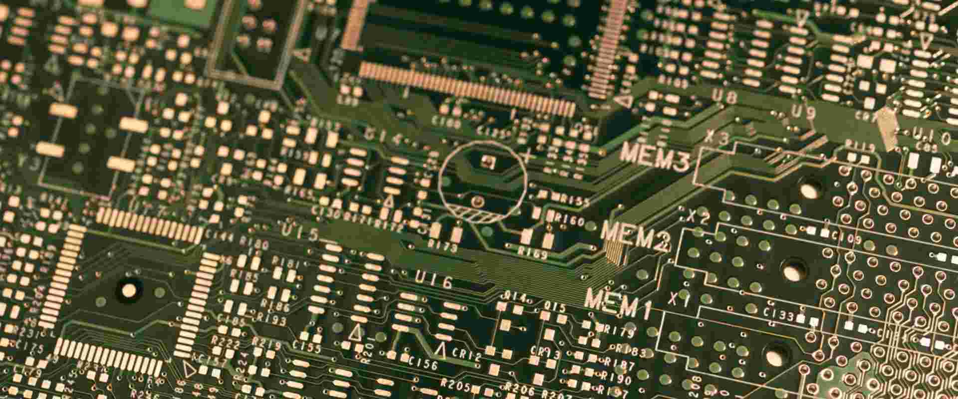
USA PCB Manufacturer and Assembly is a service provided by Advanced Circuits, a global leader in quick-turn Printed Circuit Board manufacturing and assembly. To help you get started, Advanced Circuits offers free PCB design software and file check. Advanced Circuits specializes in Commercial, Military, Aerospace, and Medical PCBs. Advanced Circuits’ PCB manufacturing capabilities include laser-drilled microvia, microwave & RF, and 40-layer boards.

It is one of the largest PCB manufacturers in the US. They offer rapid PCB manufacturing with 24-hour live tech support. Their on-time shipping record is second to none, and they provide free file reviews and expedited delivery options. Advanced Circuits has one of the largest databases of PCB manufacturing customers in the country. Their list of customers includes companies such as Boeing, Hewlett Packard, National Semiconductor, Intel, Microsoft, and NASA.

With its additional space, Advanced Circuits will be able to improve its current capabilities while investing in capital equipment. Its high quality and quick turn-time capabilities have earned Advanced Circuits’ reputation for reliability and prompt turn times. Advanced Circuits also has additional divisions in Maple Grove, MN, and Tempe, AZ. In addition to its high-quality products, Advanced Circuits has a strong financial standing. As a result, it has expanded its operations to meet the demands of the high-reliability, defense, aerospace, military, and high-tech industries.

Increasing the number of customers, and the complexity of the electronics industry, require quick turn-around solutions. To meet the demands of the demanding electronics industry, Advanced Circuits has become the PCB Manufacturer and assembly company that offers one-stop convenience, assured quality, and quick prototype assembly. Its broad range of services extends from high-reliability medical PCBs to high-reliability, commercial, and military/aerospace applications.

Screaming Circuits

In USA PCB Manufacturer & Assembly: Advanced Circuits has become a leading company in Quick Turn Printed Circuit Board Manufacturing and PCB Assembly. They offer Free PCB Design Software, PCB File Check, and PCB manufacturing services to the Commercial, Military, and Aerospace markets. Advanced Circuits offers expanded PCB manufacturing capabilities, including laser-drilled microvia and microwave & RF boards. They can also support up to 40 layers.

With facilities totaling more than 200,000 square feet, Advanced Circuits is acting as a One-Stop-Shop for all PCB manufacturing and assembly needs. It has an expedited turn-around, excellent customer service, and reliability. They offer Weekend Turns for delivery on Monday. In addition, advanced Circuits’ dedicated team of engineers is here to help you achieve your design goals.

A well-established PCB manufacturer in the USA, Advanced Circuits continues to grow its market share in small-quantity PCB production and sales. Its expansion is a testament to its quality and responsiveness. Its responsiveness is unmatched in the industry. In March 2003, Advanced Circuits expanded its facility to 62,000 square feet, allowing it to provide even more services. This growth came with introducing its “BareBones” proto service, which eliminated the price barrier and increased the company’s demand for turnkey PCB manufacturing services.

Advanced Circuits offers a full range of PCB Solutions, including quick-turn prototypes and small and large-scale production. Their services range from quick prototype assembly to complex high-reliability medical and military/aerospace applications. Advanced Circuits is one of the leading USA PCB manufacturers, with offices in Aurora, CO, Tempe, AZ, and Maple Grove, MN. Advanced Circuit is a leader in the PCB manufacturing industry, and its reputation for quality and on-time shipping sets them apart from its competition.

Millennium Circuits

As a leader in Quick Turn Printed Circuit Board Manufacturing and Assembly, Advanced Circuits can help you create the perfect PCB. In addition to offering Free PCB Design Software, their PCB file checker can help you make sure that your PCB design is accurate. Advanced Circuits specializes in Aerospace, Commercial, Military, and Medical PCBs. In addition, their PCB manufacturing capabilities have expanded to include laser-drilled microvias, microwave & RF boards, and 40 layers.

Advanced Circuit is a premier supplier of custom and high-quality PCBs for various industries, including medical, industrial, and consumer electronics. In addition to its extensive product range is also recognized for its customer service, which has consistently garnered high ratings from customers. Further, its customer service is top-rated by many industry publications. In addition, its skilled professionals have developed a streamlined and cost-effective process.

Advanced Circuits is one of the top three board manufacturers in North America. The company has expanded its manufacturing capabilities and added a high-tech aerospace and military workspace through strategic acquisitions. In addition, Advanced Circuits has one of the largest customer databases in the industry, including Boeing, Hewlett Packard, Intel, Microsoft, and NASA. All of these companies require the highest level of PCB manufacturing and assembly.

In New York City, Advanced Circuits offers a complete suite of PCB solutions, from design layouts and fast prototyping to full spec production PCBs. Customers can also get an instant online quote for their project, making the entire process quicker and more efficient. In addition, Advanced Circuits’ quality standards are one of the highest in the industry, with the highest standards. And its commitment to quality and service continues even during recessions.

Online Electronics

Advanced Circuits has been the leader in USA PCB Manufacturer & Assembly and Quick Turn Printed-circuit board manufacturing for over forty years. Advanced Circuits offers free PCB file check and PCB design software for your convenience. Their PCB manufacturing capabilities have expanded to support microvia laser-drilled and microwave and RF boards. Their PCB manufacturing capabilities include up to 40 layers. For more information on our services, visit advancedcircuits.com.

Advanced Circuits’ expansion into a new 62,000 square-foot facility in 2003 took the company to new heights of responsiveness and sophistication. Starting with a “BareBones” proto service, the company focused on the needs of the most basic proto customers and was able to remove the price barrier to proto purchasing. In the process, Advanced Circuits’ aggressive marketing approach led to increased industry exposure and increased customer loyalty.

Advanced Circuits’ recent investments have increased its manufacturing capabilities. Laser direct imaging equipment and optimized solder mask materials are two of these investments, ensuring that each board is as high-quality as possible. These new technologies will help Advanced Circuits meet the demands of the technology market today and in the future. Furthermore, Advanced Circuits recently hired Jill Scadden as their Business Development Manager, whose role will be to identify new opportunities for their customers. Jill Scadden’s role will include collaborating with customers to identify custom-designed solutions and improve overall customer satisfaction.

Conclusion

Advanced Circuits’ facilities are certified to meet UL standards. Advanced Circuits’ multilayer boards pass UL certification, and their GB/T29490 certified manufacturing process is compliant with UL standards. Its MES system also meets strict process and data controls. As a result, it is an award-winning solution that is cost-effective and environmental-friendly. In addition, Advanced Circuits has won the Metro Wastewater Reclamation District’s Gold Award for ten consecutive years. This award demonstrates Advanced Circuits’ commitment to environmental excellence.

Xilinx XA7A100T-1CSG324I FPGA Chip for Sell

Xilinx Spartan-7 FPGA

Xilinx XA7A100T-1CSG324I belongs to the Xilinx XA Artix-7 (Automotive) Field Programmable Gate Arrays (FPGAs). This series is an improvement on the Xilinx Spartan-6 FPGA family that has lower logic per watt.

We explained the important specifications of the Xilinx XA7A100T-1CSG324I FPGA in this article.

About the Xilinx XA Artix-7 Family

The Xilinx XA Artix-7 family is a series of Field Programmable Gate Arrays (FPGAs) manufactured by Xilinx. It is designed to be an upgrade to the Xilinx Spartan-6 family, especially in terms of offering improved logic per watt.

One of the major features of the Xilinx XA Artix-7 family is the design for high-volume automotive uses. This is way above what the Xilinx Spartan-6 series offers. In addition, this series offers flexible and compact packaging, thanks to the small form-factor packaging.

Thus, if you are looking for a Field Programmable Gate Array (FPGA) for your next high-powered automotive use, look no further than the Xilinx XA7A100T-1CSG324I.

Attributes of the Xilinx XA7A100T-1CSG324I FPGA

Here are some of the unique features of the Xilinx XA7A100T-1CSG324I Integrated Circuit (IC):

1. Operating Temperature

The temperature of an Integrated Circuit (IC) should not be too hot or too cold. In the case of the Xilinx XA7A100T-1CSG324I, its temperature falls within two (2) automotive temperature grades. These are:

I-Grade

For the I-Grade, the operating temperature of the board should be anywhere between 40-degree Celsius and 100-degree Celsius.

Q-Grade

Field Programmable Gate Arrays (FPGAs) that fall under the Xilinx XA Artix-7 Q-Grade fall under an operating temperature rating of 40-degree Celsius and 125-degree Celsius.

The Xilinx XA7A100T-1CSG324I falls under the I-Grade operating temperature rating. Besides, FPGAs under the Xilinx XA Artix-7 series meet the highest standards of automotive operating temperatures.

Input and Output (I/O)

Input and Output (I/O) in an FPGA refers to the physical structures on a circuit board that allow the designer to establish connection between the FPGA target and the other (external) devices in the electrical system.

The Input and Output (I/O) typically works by translating or transmitting either an analog or digital signal to or from a digital value. It is through this process that the FPGA target can be used to process the signals.

A total of 210 Input and Output (I/O) resources are available on the Xilinx XA7A100T-1CSG324I FPGA.

According to the specifications of the Xilinx XA Artix-7 series, the Input and Output (I/O) logic is configurable by either registration or combination. Either of these methods are supported by the Double Data Rate (DDR).

Also, delays can be implemented on the inputs. These delays are generally classified as IDELAY and can be delayed up to 32 increments, with the variables being 78 ps, 52 ps and 39 ps.

Additional Attributes

Here are some of the additional attributes or specifications of the Xilinx XA7A100T-1CSG324I FPGA:

  • Package Style: Fine-Pitch, Low-Profile, Grid Array
  • Moisture Sensitivity Level (MSL): 3
  • Peak Reflow Temperature (Cel): 260
  • Total RAM Bits: 4976640
  • Mounting Type: Surface Mount Technology (SMT)
  • Package Body Material: Plastic/Epoxy
  • Total Number of CLBs/LABs: 7925
  • Number of Terminals: 324
  • Part Status: Active
  • Total Number of Logic Cells/Elements: 101440
  • Package Code: LFBGA (Low-Profile, Fine Pitch, Ball Grid Array)
  • Technology: CMOS (Complementary Metal Oxide Semiconductor)
  • Supply Voltage: 0-95 V ~ 1.05 V
  • Terminal Finish: Tin/Silver/Copper (Sn/Ag/Cu)
  • Terminal Position: Bottom
  • Terminal Form: BALL
  • Terminal Pitch: 0.8 mm
  • Width: 15.0 mm
  • Length: 15.0 mm

Tips on Choosing the Best Field Programmable Gate Array

Here are some tips on how to choose the best Field Programmable Gate Array (FPGA) for your next automotive design project:

1. Performance of the Circuit Board

One of the major considerations for choosing a Field Programmable Gate Array (FPGA) is the performance of the board. Ideally, manufacturers specify the functionalities of the board and this gives you an idea of what to expect from it, in terms of performance.

In the case of the Xilinx XA7A100T-1CSG324I, it is designed for high-end automotive applications. This is because of the improvement in the previous Xilinx Spartan series that lagged in per watt logic.

2. Number of I/Os in the Board

Another important factor to consider is the number of Input and Output (I/O) pins on the board. The higher the number, the higher the chances of integrating as many functionalities as possible on the board.

The Xilinx XA7A100T-1CSG324I has a total of 210 I/Os, meaning 210 openings for establishing connection between the FPGA target and the other devices in the electrical system.

3. Speed Grade

What is the speed grade of the Field Programmable Gate Array (FPGA)? The Xilinx XA7A100T-1CSG324I has a 2-speed grade.

By design, a speed grade is used to highlight the highest operating frequency of the board. It is also used to correlate the operation of the chip with the actual design of the board.

4. Device Migration

Letโ€™s say that you purchased the Xilinx XA7A100T-1CSG324I, but for some reason, you want to upgrade. Not all Field Programmable Gate Arrays (FPGAs) support that. However, you are lucky to do this if you are using the Xilinx XA7A100T-1CSG324I, one of the boards from the Xilinx Artix-7 FPGA.

This series of FPGA from Xilinx offers a feature called Device Migration. The feature allows for upgrade of a Field Programmable Gate Array (FPGA) to a higher variant of the board.

To that end, this is one of the major ways you can derive maximum functionality from the board while saving costs you could attracted by purchasing a new board.

5. Clock Management

The management and optimization of the clock to function optimally is another important factor to consider when choosing an FPGA. The Xilinx XA7A100T-1CSG324I Integrated Circuit (IC) takes a cue from the excellent clock management architecture of the Xilinx Artix-7 series.

Each of the FPGAs in this series offers up to six (6) Clock Management Tiles (CMTs) that include a Phase-Locked Loop (PLL) and a Mixed-Mode Clock Manager (MMCM).

Final Thoughts

Rayming Technology (RayPCB) is a reliable designer of a wide range of Field Programmable Gate Arrays (FPGAs), including Xilinx XA7A100T-1CSG324I Contact us today for a quote!

Peer Analysis of Schweizer PCB – High Quality, Affordable PCBA Manufacturing

PCB assembly in the UK

In this article, we will examine the financial position of SCHWEIZER ELECTRONIC and examine the company’s financial position through Peer analysis. Also, we will use Eikon Data API to retrieve data and demonstrate how to compute growth rates. We will use Peers() and the get_data method to do this. We will then calculate the growth rate of SCHWEIZER ELECTRONIC against its peers.

Peer review

The Swiss-based company has a 90% approval rating from its peers. Its primary competitors include BAR Bahnsicherung, Zonegreen, and m2 railgroup. To learn more, visit Rayming PCB & Assembly. There you will find an overview of its product portfolio and services. If you are looking for peer review services, check out the Swiss-based company’s website. You’ll be able to access its peer review process from the comfort of your own home.

We can submit the first manuscript version as a single file up to 30 MB in size. Moreover, you should submit figures should in separate files. If they are not in separate files, they will be grouped and delay the publication process. Also, remember to follow the guidelines regarding supporting information.

Peer group

A peer group is a group of similar entities. These entities share similar characteristics, such as size, industry, and business practices. These groups serve a useful purpose in business, advertising, and academic fields. This analysis can help you identify trends and anomalies within a company. To find out how SCHWEIZER ELECTRONIC’s stock performance compares to its peers, you can use data from the SEC and corporate websites.

The construction of peer groups relies on several analyses of companies. These analyses can help you identify how SCHWEIZER ELECTRONIC compares to its peers in different industries. Using the Eikon Data API, you can retrieve the company’s financial information and identify its relative strength. You can also calculate growth rates using the Peers() function and get_data method.

Another important aspect of peer group formation is how well students know each other. For example, using the SCHWEIZER ELECTRONIC peer group, students could identify the individuals who they worked with during practical classes and the frequency of their interaction with these people.

Value examination

In a value analysis of SCHWEIZER ELECTRONIC, the factors to consider are its profitability, liquidity, solvency, and efficiency. In addition, the company’s current valuation is above its business model’s value. This is indicative of a potential capital market correction. Therefore, the value analysis of Schweizer Electronic should include a qualitative component as well. In addition to quantitative factors, value analysis should also consider the company’s competitive advantage and ability to counteract the threats in the marketplace.

A value analysis of SCHWEIZER ELECTRONIC includes assessing the product’s performance. A company may not use a product if it fails to meet agreed performance characteristics.

While Switzerland is the largest semiconductor market, Schweizer Electronic should consider a diversified supplier portfolio. This helps the company minimize disruptions in supply chains and source products at competitive prices. However, its suppliers’ bargaining power is relatively low in the Technology sector. Further, the company should diversify its suppliers’ portfolio, allowing it to control a wider range of suppliers. It also helps it deal with unexpected supply disruptions and keep costs down.

Financial position

The financial situation of SCHWEIZER ELECTRONIC in 2021 reflects a strong turnaround. Despite the challenging European market, the Group achieved a turnover of EUR 90.6 million, up 19 percent from the previous year. The turnaround was also evident in the results of earnings. As a result, EBITDA increased by almost 20 percent, and the company’s equity ratio rose to 43.8%. This result is an excellent result considering the current state of the company’s market.

The company’s sales and EBITDA were within expectations. As a result, the equity ratio at the end of 2021 was 5.3 percent, down from 17.4 percent. This equity ratio includes the shareholding in the SCHWEIZER Chinese subsidiary of strategic partner WUS Printed Circuit (Kunshan) Co., Ltd., completed in January 2022 as part of a capital increase. The SCHWEIZER Group has added about EUR 10.5 million to its capital with this shareholding.

SCHWEIZER offers a comprehensive range of PCB solutions with state-of-the-art production facilities in Germany and China and close collaboration with leading technology companies. Its products and services are helpful across the communications and computing industries. The company also provides extensive consulting services to help clients find the best PCB solutions.

Market volatility

Even though Bitcoin is a relatively new asset, it can be very useful to know how volatile this asset can be. A simple sensitivity analysis can determine how much Bitcoin is worth based on its volatility. For example, if volatility were half as high, the minimum variance weights would increase to 0%, while optimal Sharpe ratio weights would decline to 30%. However, if volatility were half as high, a lower sensitivity analysis would have little influence on portfolio weights.

The parameter estimates for Bitcoin-related events have a weak but non-negligible effect on volatility. Attacks involving bitcoins have a higher unconditional variance than normal. The COVID-19 pandemic has a similar impact on volatility, but the difference is not statistically significant. It is important to note that this analysis is not robust enough to identify a significant event.

This study also investigated the spillover effects between Asian stock markets. It included India, Pakistan, Sri Lanka, China, Japan, and Hong Kong. The researchers employed GARCH models to capture the spillover effects. While the research findings are not yet conclusive, they provide a framework for further research.

Competitors

A SWOT analysis is an essential tool for analyzing a company’s strengths and weaknesses in its industry and the external environment. The macro-environment refers to technological development, political environment, economic environment, and social climate. According to a study, 75% of managers use SWOT analysis to improve their companies’ strategies.

The primary competitors of SCHWEIZER ELECtronic are the Swiss and Japanese companies, which make printed circuit boards. However, this does not mean that there are no other companies that make printed circuit boards. Several other companies in the industry, including APCT, Sierra Circuits, and ECI Technology. These companies specialize in manufacturing and assembly services for the electronics industry.

To compete in today’s global market, Schweizer Electronic must create a robust strategy for fighting disruptions from various sources. Two of the significant disruptions are climate change and energy requirements. In addition, the EU has identified this as a top priority. These factors will bring new competitors into the Semiconductor market.

Approval rating

The Swiss certification body EFSA has awarded the company a five-star approval rating. The company provides certifications and certificates that ensure that its products and services meet all relevant quality, safety, and environmental requirements. As part of this rating, customers get a guarantee for the products and services. The company also covers the cost of warranty repairs and replacements for defective items.

The company has a high approval rating, thanks to its board of directors and CEO, Peter Schweizer. The company’s chairman and CEO have a ninety percent approval rating and serve on the audit committee. The company has several primary competitors, including BAR Bahnsicherung, Zonegran, and m2 railgroup. Aside from the audit committee, the Supervisory Board comprises five independent members, including Michael Kowalski, an independent consultant and President of WUS Printed Circuit (Kunshan) Co.

The company offers a wide range of track warning systems, including temporary and permanent trackside systems. It is a subsidiary of Schweizer Electronic AG, a Swiss company with more than 50 years of experience in train detection. The company offers complete customer support, training, and maintenance services. Schweizer Electronic is a family-owned company with many dedicated employees and suppliers. The company’s headquarters continue to develop the next generation of track warning systems. This includes a radio-based model called the Minimal Lynx.

Osmond PCB Design Software for Quality PCB Manufacturing

Doosan DS-7409DV PCB

A free Osmond PCB design program is available online, and novice and experienced PCB designers can use it. Users can find tutorials, support materials, and even custom libraries. In addition, the Osmond PCB designer program promises flexibility, allowing users to use Metric and Imperial units. Users can even use both systems within the same design. This article will explore some of the features of Osmond’s PCB design program.

Detailed description

Osmond is a tool that can help to design printed circuit boards. It supports various shapes of pads, such as round, oval, and rectangular. Its flexible features include variable trace width and spacing. It supports both metric and imperial units and allows you to work with either unit type. It can import schematic capture applications and also maintain design rules. You can also use different language formats for creating your designs, including Gerber, Excellon, and DXF.

Uninstalling OS X applications is simple. You can drag the application to the Trash, but you might wonder whether it’s genuinely uninstalled. If so, you’ll need to check for remnants of Osmond PCB 1.1.30, which might not do any damage, but will eat up disk space. If you find any, you can delete them. Then, your Mac will be free of Osmond PCB 1.1.30.

You can easily remove Osmond PCB using MacRemover, a professional uninstaller. The program works in three simple steps. First, you can use MacRemover to delete any corrupted or unwanted applications from your Mac. You can try this tool for free now and see how it works! Then, drag the icons from your applications folder to remove Osmond PCB 1.1.28.

Osmond PCB 1.1.30 is a Business Software application for Mac users. The application is designed for Mac users and can be installed and operated on your Mac by dragging and dropping the application package into the Applications folder. Once installed, the application is very easy to use. To uninstall Osmond PCB 1.1.30, follow the directions below. You can use the Finder to choose the application or select it from the Applications folder.

Features

The Osmond PCB design software has many useful features. It supports both Imperial and Metric units and can be switched between them easily. It can import schematic capture applications and maintain design rules. Its features include automatic part and net alignment and a new grid to align parts. The Osmond design software is fully functional and free to download, but users of advanced designs should purchase a license for printing and output.

Osmond is easy to use, and it provides tools to help you design high-precision PCBs. It supports pads of different shapes and sizes. You can place parts anywhere on the board, and you can define multiple copies of a design in different orientations. The Part Editor allows you to define new part types, including through-hole and surface-mount, and provides several auxiliary layers. The Osmond PCB design software also has a built-in programming language, allowing you to define arbitrary part shapes and layouts.

Osmond allows you to move parts and reorient them easily. You can also edit existing traces. The Osmond PCB design software allows you to change the part stacks and use your Mac’s font library for your PCB labels. Other features of this design software include creating custom label types and retracing existing designs. You can also import any PDF document to use as a background image.

File information

You have come to the right place if you are looking for Osmond PCB file information. Osmond dumps its GerberFiles file into the same folder as the design. The file names may vary from company to company, so it is necessary to check the naming conventions before you start modifying your designs. To identify the layers on your board, you can add text outside the PCB area. Also, make sure that your mask and ident color are among the relevant layers. Lastly, you can also use aux layer 1 to outline the board.

Mac users can search for files by using Spotlight or Finder. Then, double-check whether the files belong to Osmond PCB 1.1.30. If they do, use the rm command to delete them. This may sound not very easy, but most users aren’t that tech-savvy. However, if you’re a pro with macOS, you can follow the instructions below to uninstall Osmond PCB.

Uninstall options

Besides choosing the “Complete uninstall” option to get rid of Osmond PCB, you can also opt for a system reset. When you perform a system reset, you will have the option to clean up all the files associated with Osmond PCB 1.1.27. Once you have finished the uninstall process, you can click “Finish” to close the uninstall window.

To begin using the Osmond PCB software, you must first download it. If you are a Mac user, you can also install the application on your system for free. Regardless of whether you have an older version of OS X, the software is free for Mac users. Furthermore, it is donationware, so it comes with no restrictions. The best part is that it does not cost anything to download.

When removing Osmond PCB 1.1.30 from your Mac, you should empty your Trash. Alternatively, you can also use a program like MacRemover to remove this unwanted application from your computer without the hassle. MacRemover is a highly advanced uninstaller for Mac and can safely locate and remove all program files. It is even capable of removing hidden files. So, no matter what version of Osmond PCB you’re using, you can safely remove it from your system.

To remove Osmond PCB from your Mac, you need to open the Applications folder in the Finder. Then, click the “Uninstall” button to locate the app’s executable file. The uninstaller will then move to the Trash, which we can empty after removing the program. If you want to uninstall Osmond PCB 1.1.27 from your Mac, two options are available.

Application areas

AppWare designs and utilities for Mac OS X. They offer a variety of software and applications for the Mac platform. They also develop software for all major operating systems, such as Linux, Windows, and FreeBSD. Due to their huge database of software applications, you can easily find the right application. Their site also offers a large database of technical information and user manuals.

The Osmond PCB design software is relatively small, but it is still fully functional for users of all ages. The program is free to download, so there is no need for any credit card or other payment information. You can find it on your favorite download site. Once you have downloaded the app, install it and use it.

Osmond PCB 1.1.30 is a small and simple application that offers excellent features for its users. It came at an affordable price, which means that many Mac users will be able to use it without any issues. In addition, the software has many powerful tools, such as a built-in programming language. This is an excellent option for makers and hardware developers who want to build custom projects.

Many advanced features can create very accurate designs on your Mac. For example, the Osmond PCB design software lets you design high-precision PCBs with ease. For more information about this app, please visit Rayming PCB & Assembly.

Conclusion

The Osmond PCB design software is a fully functional and easy-to-use software that offers its users great features. It provides all the tools you need to create high-precision PCBs. Also, the design software’s layout editor can create any part layout you want. It also allows you to edit existing traces, add text as a background image, and manipulate your parts. In addition, you can use aux layers to move parts.

The software is also available in different languages, such as English and German. So, it can be easily helpful to people around the globe. Moreover, the software is donationware and will not cost you a cent to download. So, there is no need for you to worry about the payment information that Osmond needs from you. So, when you get Osmond PCB 1.1.30 on your Mac, you can use it without any worries or problems.

How to Make the Most of EDA PCB Design Software Tools

free PCB Design Softwares

Choosing the right software for PCB design is crucial for successful circuit creation. Several different EDA PCB design tools include EasyEDA, Capture, gEDA, and Altium Designer. First, read on to learn more about the most popular EDA PCB design tools and what they can do for you. Next, you’ll learn how to make the most of each tool by following these four steps. Then, if you’re ready to begin creating your circuit board, download one of the three software tools below:

EasyEDA

EasyEDA allows you to create and edit PCB designs. This tool saves you time, effort, and money and can import and edit your existing designs. It even includes a free Gerber Viewer that you can use to view, modify, and edit your schematic diagrams. You can also share your PCB designs with other colleagues or publish them on the internet. You can also make a online PCB design as large as 100cm x 100cm.

The software allows you to customize your PCB by adding text or images. You can change the text in the Properties menu and even change the color of the PCB. Then, you can order your PCB. EasyEDA PCBs also allow you to order PCBs. If you need a prototype, you can buy the PCBs you’ve created in the program. Alternatively, you can use an online PCB fabrication service to create a PCB design for your prototype.

Using EasyEDA, you can design a PCB for your project with the help of a professional PCB fab. The PCBs from EasyEDA are top-quality and guaranteed to be error-free. You can even add a solder mask with precise tolerances to the design. As a result, no errors will be visible, and the printed circuit board will be 100% E-tested, meaning no worries about quality. Designed PCBs are essential to electronic components and electronics.

The software has many benefits over a PC-based PCB design. It’s web-based and always updated, so you can use it on the go from wherever you are. Furthermore, it’s easy to share your finished designs with other users. EasyEDA also makes ordering a PCB design easier with its state-of-the-art equipment and professional staff. EasyEDA is a valuable tool for every hardware engineer with all these benefits.

Capture

Many electronic designers are familiar with Altium’s schematic capture and layout tools. They can use Altium for schematic capture and layout, and it comes linked to a component library on the internet. These tools allow you to simulate circuit boards using SPICE simulation when creating prototypes. Altium also includes an Electro-Magnetics solver that calculates propagation delay and impedance. Ultimately, these tools can make your design much faster.

When designing a circuit board, it’s imperative to use a specialized PCB software application that can generate the correct parts libraries. Capture is a prime EDA application, and it includes extensive parts libraries. It also interacts with other electronic design tools, including PCB Editor, which converts schematic diagrams into physical models. The three applications work together to create a powerful set of tools.

To create the schematic layout, you first need to check for the right symbols in the CAD library. Once you have a list of symbols, you can begin placing them on the schematic. The design tool you choose will allow you to drag and drop symbols to make them appear neatly.

You can also import schematics from a library on your computer. The software makes it easy to use and has many components. In addition, EasyEDA allows you to modify existing designs to fit your specific requirements. For example, you can customize the color to see your PCB after fabrication. Capture EDA PCB software is free to use. And there’s an excellent user interface for creating and editing PCB designs.

gEDA

PCB and gEDA are free and open-source electronic design automation tools for creating circuit boards. Both are capable of low to mid-level complexity. gEDA allows the creation of PCBs with up to 8 layers and unlimited nets and components. Users can choose to use them as hobbyists, educators, and small and large companies. The gEDA community has a mailing list to discuss the software’s development.

The gEDA software suite consists of many different tools and utilities. The main PCB layout creation tool, gschem, has a compact user interface and several functionalities. Besides capturing schematics, gschem can also generate netlists and create a PCB design. In addition, several tools in the gEDA suite can perform essential tasks, such as generating schematic symbol files and checking for common errors.

The gEDA toolkit is a product of developers who share the same vision. Several gEDA users have participated in the Google Summer of Code as a single project. The gEDA acronym stands for GNU General Public License. To learn more about this project, visit Rayming PCB & Assembly. It contains a list of FAQs and official documentation. If you’re unsure about using the gEDA toolkit, you can join the mailing list and learn more about the software.

The gEDA symbol library contains a search engine and official libraries. It also lists contributors who contribute symbols, footprints, and tools. In addition, the gEDA website contains the official symbols and the gaf file format spec. These tools are available to everyone who uses the gEDA software. Therefore, it’s essential to download the latest version of these tools and utilities for the gEDA software.

Altium Designer

Using the unified design platform in Altium Designer for EDA PCB allows users to work more efficiently and make changes to their schematics and designs more easily. The software features editors for each design domain, ensuring that each step of the process is covered. The program guarantees the presence of a schematic editor, a symbol editor for SCH libs, and a spice engine built on top of the schematic editor. Altium Designer supports the Berkeley spice models and p-spice.

It has all the capabilities you need to design PCBs and automate the manufacturing process. With various features, Altium Designer is the best EDA PCB design software on the market. It can handle complex, multi-layer designs, custom cad files, simulations, and footprints. It also supports enclosures and provides 3D cad files of the final PCB. The only downside to Altium Designer is that it can consume a lot of processing power, which discourages using this tool for simple editing. It is, however, the perfect tool for those who know what they are doing.

One of the greatest strengths of Altium is its 3D rendering feature. This feature is beneficial for large-scale enterprises and large enterprises that may not have the resources to learn the program. However, it is not recommended for smaller companies because the program requires a subscription, and there may be bugs and partially implemented features in new versions.

Scheme-it

Digi-Key recently updated its Scheme-it for EDA PCB with new features that streamline schematic design and early design concepts. These features include part information management, BOM export, and easy sharing of projects with colleagues and clients. The latest version also features a new Symbol Editor with 2.0 support. Users can create new symbols and modify existing ones with ease. The software also supports higher-level symbols, such as a yellow arrow in the center of a symbol.

The latest release of Scheme-it for EDA PCB is free to download and use. The free online schematic drawing tool has a full library of electronic symbols, an integrated Digi-Key component catalog, and a built-in bill-of-materials manager. Users can even export schematic drawings to images. It also works natively with major web browsers without third-party plugins and is compatible with all major operating systems. In addition, registered users can share and save designs to a public or private server.

The EDA PCB software also has several useful tools, including a text editor and primitive graphic forms. It also offers a document reference point. The drag-and-drop tool allows users to move and logically zoom elements. It also connects elements, allowing the user to modify the layout without reopening the PCB editor. In addition, EasyEDA supports automatic layer-stacking.

Allegro PCB Designer – Home of Amazing Boards and OrCAD Connected

Altium PCB design process

Allegro PCB Designer is a powerful unified system design and analysis platform. It supports a variety of design processes, including phototooling, bare-board fabrication, and test outputs. Allegro PCB also connects to Oracle Agile EDM systems. Learn how Allegro PCB can help your team increase productivity and ramp-up to high-volume production in record time. Let’s explore some of the benefits of Allegro PCB Designer below.

Allegro PCB is a unified system design and analysis platform

The Cadence Allegro PCB Editor enables designers to bring innovative designs to life, reducing design time and cost with its comprehensive tools. Its advanced routing algorithms and low-density features allow you to optimize the design process and minimize the number of iterations. The Allegro PCB Editor also supports RF antenna and high-speed designs. Designed to support the design and analysis of electronic systems, the Allegro PCB Editor is flexible enough to meet any online PCB design requirement, including large, complex, or low-density designs.

Integrated with Allegro PCB and IC package design, Allegro Sigrity SI supports advanced SI analysis early in the design cycle. It reads from a design database and provides embedded field solvers and IBIS models. As a result, Allegro PCB and Sigrity SI can model multi-layer ICs, including parallel and serial channel architectures.

The seamless schematic data transfer software eliminates manual re-entry of RF/microwave design information. As a result, RF/microwave designers can use Allegro-compatible IP for all their RF/microwave designs, eliminating manually replacing components or redrawing the entire circuit. In addition, we can import Allegro PCB designs into the AWR Design Environment platform for high-performance multi-physics analysis and design verification.

AWR’s technology and unified libraries make AWR easy to integrate with other software systems. The AWR software also supports Cadence technology files and unified libraries. This makes it possible to design complex electronic systems while maintaining a high level of interoperability. The Allegro PCB and IC package design platform can support diverse RF designs and reduce design time by 50%.

It connects to the Oracle Agile EDM system

XPLM’s integrate2 platform links applications like Allegro PCB and OrCAD with the PLM system Oracle Agile EDM to support multidisciplinary item information management. Developed for mining, exploration, and mineral advancement, this web-based information management system is available for various markets. Users can view and download updates for both applications in one window. In addition, users can also download updates for OrCAD.

The Allegro EDM solution integrates design data management, library management, and style procedure control to streamline the entire process. This comprehensive solution enhances workgroup efficiency and reduces costly errors, such as faulty parts. With a standardized interface, job members follow the same procedure, reducing the need for manual data entry. The system also provides a streamlined workflow to ensure that all job members follow the same process and maintain consistent quality.

We integrate a database for the Allegro EDM with the Agile EDM system. This database contains tools to reduce the time required to schedule information. By synchronizing the information in an EDM SQL database, the software will reduce the time needed for a single job. Moreover, it also allows the user to access data on all workstations, whether they’re on different servers or the same computer.

It provides phototooling, bare-board fabrication, and test outputs

The software offers a range of phototooling and bare-board fabrication options to suit the most demanding requirements. Among its key features is the Allegro PCB Librarian, a powerful and versatile part production solution that removes the need for manual recognition of schematic signs. The program also allows you to produce BGA real estate with complex traces and pad apposition, reducing the time and cost of producing new products.

The Allegro PCB Designer offers a PCB Editor and an auto-interactive router. It also provides interfaces with mechanical and production CAD systems. The PCB Editor is a complete positioning and routing environment with advanced adjoin preparation and duplication options. It also offers a wide range of tools for preparing and checking PCBs, including the production of PCB files.

Allegro PCB is a scalable, constraint-driven layout system with powerful programmability and design capabilities. Its powerful features enable designers to design circuit boards with high-end performance, including layout partitioning and RF/analog and mixed-signal interconnect planning. In addition, its unique layout environment can help increase productivity. It also offers real-time heads-up displays of margins and dynamic shape capability.

Designed for PCB designers, Cadence Allegro PCB Librarian supports the process from concept to production. Its scalable base-plus-options style system matches a small-to-large business’s technological and methodological demands. The software also supports the import/export of information from other EDA suppliers’ libraries. In addition, it supports common market file formats and offers numerous effective functions, including RF style capabilities, pin table partitioning, and adjoin style preparation.

It has integrated analysis workflows

The most significant difference between Altium and Allegro PCB design software is how the two automate routine tasks. The former makes use of a feature-rich workflow, automating many routine tasks. On the other hand, the latter allows you to customize your workspace and connect parts within the circuit. While both offer robust functionality, the price difference makes Allegro the better option for many businesses.

The software is scalable, which means it can grow with your business and meet future needs. For example, Allegro PCB Design CIS depends on an integrated analysis workflow. You can use an analysis workflow to validate your design and improve it. The software offers advanced capabilities, with integrated flows and real-time visual feedback. Furthermore, Allegro PCB Designer’s multi-style environment is industry-first.

In addition to the design features, Allegro has a featured kit that allows multiple designers to work on a project simultaneously. Several tools, including a documentation editor, make it easy to document designs and collaborate globally. The software also provides a library creator, enabling designers to design 3D packages simultaneously, including MCAD and ECAD models. Users can also edit connectivity, which is a feature that comes with the Allegro/RF option.

It is scalable

You can create any PCB design in Allegro PCB. It has several tools to create individual parts. The program also supports automatic PCB routing. To create a PCB, you first have to create a design file. There are two main file types: Standard and Professional. Select the appropriate one for your needs. After creating the design file, you must add the PATH environment variable to the project.

With Allegro PCB Designer, you can quickly place and route similar circuits. You can even create a template from a placed circuit. It supports RF design capabilities, RF simulation, and interconnect design planning. Allegro PCB Designer has proven to increase engineers’ productivity and ramp up quickly to volume production. The software’s scalable model allows Rayming PCB & Assembly to adapt the tool to their changing production demands easily. In addition, the software’s extensive capabilities enable engineers to create complex PCBs quickly and easily.

All the tools included with Allegro PCB Designer are scalable. With the ability to add, delete, or modify any part, Allegro can take simple designs and turn them into production-ready circuits. Allegro also supports the constraint-driven design. It’s scalable and can handle any technological demand you might face. It can also handle any project, from high-speed to RF antenna.

If you’re considering using Allegro for your next PCB design, what features you need most are worth considering. Allegro PCB Designer offers many features, but it’s also costly, so it might not be appropriate for you unless you have years of experience. You may be better off using OrCAD if your design is not too complex.

What You Should Know About Fares PCB Assembly – PCB Design for Smart Card, RFID, and Other Circuits

Shengyi S1000 PCB

Printed circuit board assembly is a common process performed in electronic equipment, ranging from small home appliances to large industrial devices. This process connects various PCB layers and IC pins using electroless copper plating. Electroless copper plating is most used for lead-attached components, making it easier to insert them into drilled holes. Electrical assembly is an umbrella term for everything associated with the current flow control, including wire harness and cable assembly. Another term for this process is box-build assembly.

Printed circuit board assembly

Printed circuit board assemblies are the heart and soul of the human-machine interface. The process of PCB assembly involves several steps and follows precise guidelines. The PCB manufacturer uses a screen template, controlled heating, and cooling mechanisms, and a sophisticated assembly system to ensure that every component is aligned perfectly. As a result, even the slightest deviation can affect the functions of the finished board. Listed below are some things that you should keep in mind before selecting a PCB assembly service.

PCB assembly services require you to provide the design file for the PCB. Next, they check this design for issues, including any overlapping parts, missing components, or redundant components. These can negatively impact the final product. Similarly, PCBs may not have the correct spacing between components, causing shorts and malfunctions. To ensure that your PCBs are safe, the process must include a thorough inspection and test to identify any flaws.

Printed circuit boards are expensive to produce. Programming and startup costs all contribute to the final cost of assembly. Increasing the number of printed circuit boards to be assembled will save you money in the long run, as you will not have to repeat the process over. To avoid such costs, you should work with a PCB assembly service that has a large capacity. With a large production volume, you can ensure that the PCB assembly services will be high quality and fast.

Printed circuit boards are helpful in everything from household lighting to aerospace devices. Even the most mundane electronic device requires a PCB for functionality. Fares’ printed circuit board assembly service can provide the necessary PCBs to ensure the quality and efficiency of your products. So, you can rest assured that your business is in good hands with Fares PCB assembly.

Fares PCB Microcontroller Kits

If you’re thinking of building your Arduino-based microcontroller, you may consider purchasing a Fares PCB Microcontroller Kit. The Fares PCB Microcontroller Kit is a pre-assembled board that contains the necessary components for building an Arduino-compatible microcontroller. Whether you’re making an educational device, a consumer electronic device, or a medical-device application, the Fares PCB Microcontroller Kit is an excellent choice.

Featured products

You’ve come to the right place if you’re looking for a complete PCB Microcontroller Kit. Fares’ PCB Microcontroller Kits feature several different chips and modules. These include the AMD A8-C7100, which features two high-speed USB 2.0 interfaces, a parallel RGB888-output LCD interface, and two USB 2.0 ports. Other features include Secure Boot and TrustZone support, NAND flash, and an external bus interface.

The STK200 starter kit is an entry-level microcontroller kit with a DIP socket for an AVR chip in a 20 or 64-pin package. It features an on-board debugger, user LED, and reset button. It also features a general I/O and an RS-232 port. In addition, the STK200 starter kit includes a programming dongle for the AVRISP microcontroller, which connects to the PC via a serial port and draws power from the target system.

It has a built-in programmable debugger and uses the MPLAB X IDE for programming. You can debug programs, evaluate applications, and use the in-circuit debugger to troubleshoot your program. You can even debug applications without using any paper! All Fares PCB Microcontroller Kits come with a step-by-step instructional guide and a USB cable.

The SAM4S Xplained Evaluation Kit is an ideal platform for early evaluations of the SAM4S. It features QTouch(r) button sensors, LEDs, a USB port, Xplained expansion headers, and an emulator for JTAG. It also comes with a USB cable and RF Transceivers for debugging purposes.

The Explorer 16/32 Development Kit is an extremely flexible and convenient development platform. It comes with everything you need to begin developing applications right away. It supports sixteen-bit PIC24 and 32-bit PIC32 MCUs and includes a full-featured development environment that can grow with you. The Explorer 16/32 Development Kit also supports mikroBUS accessory boards, ideal for rapid prototyping in connectivity and the IoT.

Inspection methods

There are two main inspection methods used for Fares PCB assembly: AOI and AXI. AOI uses optical inspection, while AXI uses x-rays. X-rays can penetrate both the PCB and the component body, generating 2D and 3-dimensional images of solder joints and connections. AOI may not provide the same level of accuracy as optical inspection, but it helps detect solder voids and flaws.

Inspecting a Fares PCB assembly can help ensure a high-quality product and improve overall design efficiency. For example, it is vital to check the thickness of a PCB and its surface and any warpage.

X-rays are highly-sensitive instruments that use x-rays to examine the quality of solder joints and connections. X-rays are generally used for more complex PCBs because they can reveal hidden errors in the assembly process. For example, X-rays can reveal open solder joints and component misalignment that are not visible to the naked eye. However, X-rays are expensive compared to other inspection methods and require specialized equipment.

Another inspection method is X-ray inspection. This method can examine a circuit board at five to ten joints per second. The validity of this method depends on the skills and capability of inspectors and the consistency of standards. Visual inspection requires an inspector to understand the technological requirement of each solder joint type. Because each Fares PCB has more than six types of solder joints, visual inspection is not practical for quantitative measurement.

Price

For the first-timer, it may be challenging to figure out which Fares PCB Microcontroller Kit to purchase. The basic Stamp kit was sold for $139 in 1993 and included everything you need to get started, from the microcontroller to a programmer cable. In addition, the kit contains a microcontroller, EEPROM, crystal, and voltage regulator. For the beginner, the fare is an excellent price.

Ordering

If you are interested in purchasing a Fares PCB Microcontroller Kit, you’ve come to the right place. This online shop offers inexpensive PCBs and fast DHL Express shipping to anywhere globally. You’ll need an archive file containing your Gerber files, which you can download from GitHub. You’ll also need to create an account and upload the archived files.

Shipping

When designing a PCB Microcontroller for your next project, you’ll probably want to use a USB cable for a few things. USB cables are beneficial for connecting your PC to a computer and are widely available. They are also great for connecting your PC to other electronics, such as a Raspberry Pi. In addition, you can use USB cables to connect your PC to a computer and USB hubs.

Conclusion

The global market for substrate-like PCBs is dominated by the consumer electronics sector, driven by smartphones’ growing popularity. The rest of the market splits into four geographic regions, including North America, Europe, Asia Pacific, Middle East & Africa, and South America. APAC accounts for the largest global market share, with North America and Europe a distant second. However, the growth of the PCB market is due to the increasing acceptance of these components and connectivity solutions led by large corporations like Rayming PCB & Assembly.

If you are looking for a distributor for the PCB and electronic components you need, Fares PCB for Electronic Solutions is the place to go. They have a vast selection of these products, including printed circuit boards. They also have electronic assembly services available. So no matter what type of electronic assembly you need, you can count on Fares PCB for Electronic Solutions to deliver your design on time.

Why Choose Spectra PCB Manufacturing, PCB Assembly and PCB Design Services

rigid flex PCB Manufacturers

Read on if you’ve been wondering why you should use Spectra pcbs in your projects. This article will explain the benefits and why these boards were pre-calibrated in the factory before shipping them to you. Moreover, we’ll explain why you should use them and how they work. In addition, you’ll learn how they can improve your production process by providing you with data on the availability of parts.

Spectra-Physics introduced the Talon (r) UV laser line into industrial OEM manufacturing. PCB manufacturing has traditionally relied on CO2 or excimer lasers, but UV DPSS laser technology has several advantages over these alternatives. This technology allows for more versatile and efficient processing of various materials. In addition, this PCB design software provides an inbuilt function for recording spectra in the Raman shift mode.

Spectra PCB was precalibrated in the factory

The Spectra PCB was factory-precalibrated to detect PCBs at different concentrations. The spectral values correspond to a specific wavelength. The PCB concentration in the sample increases and decreases over time, and if there is no fractionation, the PCB concentration will remain constant. However, the PCB concentration in the sample will increase relative to the PCB concentration.

Why Spectra PCB?

One of the essential parts of your business is your printed circuit board. While the task may seem easy, it’s not. Countless businesses will try to take advantage of you. If you want to make sure you’re working with a reputable manufacturer like Rayming PCB & Assembly, follow these tips. This article will provide an overview of Spectra-Tech Manufacturing’s film metrology systems, including the SpectraFilm LD10, SpectraShape 8810/8660, and the Aleris(r) SMX.

Spectra-Tech Manufacturing offers 3D shape models

With the SpectraShape 11k dimensional metrology system, Spectra-Tech manufacturing can characterize finFETs, vertically stacked NAND, and DRAM structures. This system can quickly identify subtle variations in critical structural parameters, such as device dimensions and tolerances, so that fabs can improve yields faster. It is compatible with the SpectraShape 9000 and 10K optical shape metrology systems.

Spectra-Tech Manufacturing uses the Fuji technology in the four high-speed lines for SMT manufacturing. The company can also provide conformal coating and full In-Circuit Testing using its Flying probe tester coded as SPEA 4030. It also has two advanced ERSA selective soldering machines, including a programmable solder pot. It is also a QS-9000 and ISO-9002-certified company.

SpectraFilm LD10 and Aleris(r) film metrology systems

The SpectraFilm LD10 film metrology system from spectroscopic ellipsometry technology from a laser-driven plasma light source offers high-precision measurements for thin and thick films. With this technology, you can characterize multiple layers of thin and thick films and measure their thickness and stress. These film metrology systems are perfect for measuring thin and thick films. In addition, spectra-Tech’s film metrology systems feature increased throughput and support more than one film layer.

Spectra-Tech’s Aleris(r) 8510 extends the Aleris Family’s film thickness and composition measurements to ultra-thin decoupled plasma nitridation process layers. This system provides film metrology data for DPN and high-k metal gate layers and enables you to monitor Hf and N doses.

Spectra-Tech’s Archer(r) 750 overlay metrology system provides highly accurate overlay measurements with 10nm resolution. With its advanced automation and real-time homing capability, the ATL100 is a versatile metrology system. It supports a wide variety of scatterometry overlay measurement target designs. It also supports high-order scanner corrections with increased sampling.

SpectraShape 8810/8660

SpectraShape 8810/8660 PCB is an excellent option for your memory chip needs. The SpectraShape 8810/8660 PCB has a small footprint and can be helpful for memory chips, DRAM, and other applications. It is also compatible with ICQi Jian Jin De Jian Mo Ruan Jie Shi Lai Zi.

SpectraShape 8810 and 8660 systems offer an excellent feature set, featuring multi-channel design and broader applicability across the IC fab. In addition, these systems can be used from early leading-edge transistors to final interconnect layers. As a result, the SpectraShape 8810 and 8660 are ideal for many applications, including microelectronics and high-volume electronic manufacturing.

SpectraShape 8810 and 8660 systems use various optical technologies to measure IC shapes. They can monitor complex three-dimensional shapes at production speeds with their high-speed capabilities. This is crucial for complex structures such as high-k metal gates and dual-damascene contacts, which can have minute variations in profile. With this tool, you can ensure the accuracy of your ICs without spending a lot of money on costly and time-consuming calibrations.

SpectraFilm LD10

The SpectraFilm LD10 system is an excellent tool for measuring the thickness of all film types, including single layers, thin stacks, and multi-layer PCBs. Thin layers often work alone in a photoresistor oxide. However, bigger stacks are also possible, such as 3D NAND structures.

The SpectraFilm LD10 provides high-precision measurements for thin and thick films and their stress and refractive index. Its advanced features enable engineers to monitor and qualify films with ease. It is available in various configurations to suit any PCB manufacturing application. The system is a good fit for high-volume manufacturing environments, enabling accurate measurements of patterns, film thickness, and layer-to-layer alignment.

The SpectraFilm LD10 system offers an unprecedented level of accuracy for film measurements. The system’s high-bright light source drives spectroscopic ellipsometry technology, providing precise measurements of thin-film layers for critical device parameters. As a result, this system helps manufacturers meet stricter process tolerances for leading-edge memory and logic design nodes, providing insights weeks before e-tests. Moreover, the system can accommodate increased film layers and enables manufacturers to achieve higher productivity.

SpectraFilm F1

KLA-Tencor introduces five new patterning control systems for IC fabs. The ATL overlay metrology system uses unique tunable laser technology to maintain the accuracy of overlay error measurements even with process variations and supports fast technology ramps. SpectraFilm F1 film metrology system employs new optical technologies for high precision single and multi-layer film thickness measurements. It also delivers bandgap data for determining uniformity and patterning control.

SpectraFilm F1 film metrology system enables PCB manufacturer to achieve high process tolerances at leading-edge logic and memory design nodes. It measures film thickness on the device-like grating structure. It also supports increased film layers, a requirement associated with leading-edge fabrication techniques. This system supports increased productivity and accuracy in PCB manufacturing. High brightness light source provides accurate measurements of thick and thin films.

The final product is a plastic sheet with the photo negative of the PCB. The black ink on the image represents conductive copper parts, while the clear portion denotes non-conductive material. The plotter develops the film automatically and secures it to prevent unwanted contact. Ultimately, this technology is ideal for PCB manufacturing. The advantages are numerous. These PCB manufacturing solutions are easy to use and extremely cost-effective.

Customer service

Spectra-Tech Manufacturing offers a complete range of electronics and printed circuit board assemblies. They offer a variety of services for both prototypes and high-volume production. They pride themselves on providing exceptional results. With the assistance of their customer service specialists, you will be able to benefit from world-class electronic manufacturing services. To learn more about the company, read the following. Customer service at Spectra-Tech Manufacturing begins with a personalized and thorough interview process.

They are readily available to discuss any project opportunities. In addition to being available to help answer questions, they are also available to discuss your production needs. Spectra-Tech manufacturing offered a competitive compensation package, including health insurance and paid time off. Spectra-Tech employees also enjoy generous company matching and retirement plans. Customer service representatives at Spectra-Tech Manufacturing are eager to help you find the right solutions for your needs.

Spectra-Tech manufacturing is a quality-awarded manufacturer in the Electronic and Electrical Equipment and Components sector. Founded in 1994, this company has been in business for over 24 years and generates $18.8 million in annual revenues. It employs 47 individuals at its single location. The company engages in both manufacturing and importing activities. As a result, its customers benefit from high-quality products that meet stringent quality standards.

An Overview of Meiko PCB – the world’s first Japanese company to develop a PCB

Panasonic HEPER R-1755E PCB

Meiko Electronics Co., Ltd. manufactures PCBs and PCB hole inspection systems. In addition to manufacturing PCBs, Meiko offers electricity checkers and matrix switchers. In addition, its imaging division developed the world’s first multi-vision video magnifying device. Besides manufacturing PCBs, Meiko also makes matrix switchers and converters. These products manufacture video games, consumer electronics, and medical devices.

Meiko Electronics Co., Ltd.

Meiko Electronics Co., Ltd. is a Japanese electronics company that designs and manufactures printed circuit boards. In addition, it also manufactures auxiliary electronics and industrial equipment. The company was founded in 1975 and employs more than 13,700 people worldwide. For more information, visit the company’s website. This company has multiple subsidiaries, and you may be able to find one that’s near you. This article will give you an overview of the company.

Meiko Electronics Co., Ltd. is a Japanese electronics company that manufactures anyLayer high density interconnects, printed circuit boards with high heat dissipation, and printed circuit boards with high electric current. They also sell solder stencils to Rayming PCB & Assembly. They are based in Japan, exporting their products to North America and Asia. Their products are helpful to companies worldwide, including hospitals, home appliances, and smartphones.

Meiko PCB – Automotriz

The Automotive PCB report analyzes various factors that affect the auto industry’s growth. It also examines the supply and demand in the market, distribution channels, technological developments, and more. The study is a useful tool to help you determine the scope of the market. It also offers valuable insights into the growth potential of your products.

The Automotive PCB market is now global, extending from North America to Europe to Asia-Pacific and Africa. Moreover, the latest COVID-19 pandemic has affected the market, including disruptions and financial vulnerabilities. Hence, it is imperative to understand the current market scenario completely.

The Automotive PCB market study includes the current market status, future trends, and competitive landscape. It also provides sales figures in US dollars and considers the market penetration. It also consists of the impact of the virus CORONA on the market. Further, it discusses the competitive dynamics in the market and the various factors that are essential for new and existing players. Additionally, the report provides helpful research techniques to help new and existing players in the market.

The Meiko Automotive PCB report is a valuable tool for any business owner who wants to expand their business in this sector. The data it includes helps them determine the right strategies to pursue to remain competitive. In addition, the Automotive Rigid PCB report also provides growth forecasts for the key regions of the market. With this information, business owners can decide whether to expand their business in a certain region or not.

Meiko Advanced rigid PCB

The Meiko Advanced rigid PCB report presents a detailed analysis of the Advanced rigid PCB market. It offers a complete market breakdown and information about the key players operating in the market. Furthermore, they organize the study by type, size, and CAGR to help readers make informed decisions. In addition to providing a detailed analysis of the Advanced rigid PCB market, the report also includes industry data that allows investors and participants to evaluate the market’s potential.

The Advanced rigid PCB report offers a detailed analysis of the market’s major players, key segments, and other factors influencing the market growth. It also includes information on the key trends shaping the market. Meiko is committed to providing accurate and timely information on the Advanced rigid PCB market. Therefore, this report is a valuable tool for anyone interested in the market.

Meiko PCB automotive value chain assessment

Meiko PCB, an automotive value chain assessment report, offers comprehensive data about the global market for PCB rigid for automobiles. The report includes a detailed analysis of the growth factors, market drivers, restraints, and opportunities. The report also highlights key players operating in the market. It also includes Mercado trends, Covid-19.

The PCB market research report analyzes the market trends and their implications for the global PCB industry. It also provides 2020 to 2025, based on various segments, including PCB suppliers, PCB manufacturers, and distributors. The research covers data from both the global and regional markets, including China and North America. In addition, the report includes information on regional production techniques and consumption trends.

The report provides detailed insight into the Automotive Rigid PCB market, its competitive landscape, and its regional segments. The report employs FODA technology to evaluate the market size. Several automotive industry leaders have earned a good reputation through innovative market studies. A comprehensive analysis of the Automotive Rigid PCB market will provide your company with a competitive and profitable environment.

It is a comprehensive and detailed analysis of the industry’s growth trends. Using analysis tools in your business will save you time and money in the long run. You can determine potential growth opportunities and make smarter decisions with detailed market segmentation.

The global Automotive PCB market is expanding in many areas. Besides North America, it has expanded into Europe, Asia-Pacific, and Africa. However, COVID-19 has brought significant challenges and has made the Automotive PCB market much more vulnerable. In addition, it is worth noting that the global Automotive PCB market has a much higher financial vulnerability than the global economy.

Why MEIKO

Mega-Trends: A company that makes a product like Meiko PCB should benefit significantly from the globalized economy. Meiko has grown in recent years because of its production capabilities in Japan and the global market.

Globalization:

The world is becoming more globalized, and Meiko is benefiting from this. In addition, with China becoming an economic powerhouse, it allows companies such as this one to expand their reach. Additionally, more customers will demand more sophisticated electronic devices with more people using technology devices and products.

Innovation in Technology:

Technology is constantly improving. This will continue for some time, which will benefit companies like Meiko. Because technology constantly improves, companies must keep up with the times. In addition, as technology improves, people will want more advanced electronic devices and components.

Environment-Friendly Workforce:

Japan is one of the most environmentally friendly countries in the world. As such, people and businesses that live there strive to be green. This technology company is also a great example of environmentally friendly practices. They care about the environment, and they strive to be green by making innovations in technology and being environmentally friendly.

Manufacturing Capabilities:

The company has its headquarters in Japan, and they have multiple production facilities there. They also have a production facility in China. This allows them to be close to customers and manufacture products fast and efficiently.

Sustainability Focus:

Meiko focuses on environmental sustainability. Their products have features that make it easier for them to use environmentally friendly components. Furthermore, they use recycled materials when possible.

Regional Impact:

The company is most active in Asia and the Americas. They don’t operate as many facilities in Europe as they do in other regions, which may be a problem. They may expand more into Europe and other regions to increase their production and sales volume.

Conclusion

Meiko PCB has a long history of success in production. They have grown significantly and come a long way since their beginnings. In addition, they have designed and manufactured products that have won international awards for their innovative designs and manufacturing technologies.

This company is entering a new era of rising popularity and prosperity, as more people use technology devices at home and in the office. This will benefit Meiko as more people buy these devices, especially mobile phones and tablets.

Small and Powerful PCB Board Manufacturer – What to Look for in a PoE PCB

Shengyi WLM1 PCB

When shopping for a PoE PCB, look for high efficiency, low noise level, and isolation. You should also consider the devices that Poe PCBs can power. Here are a few examples:

High efficiency

A high-efficiency PoE PCB has several benefits. High efficiency means fewer power losses and lower heat dissipation, which means lower operating temperatures and greater reliability. For example, a PD with 80% PD should require no more than 75 W of power to run. This is well over the maximum PoE power limit of 71 W. It is important to choose a suitable PCB for the power supply to avoid power loss.

A PoE PCB must have the following features: short output traces, parallel wiring, and isolation transformers. The traces for the output ports must connect to switch pulse transformers. A common-mode choke, or BMC, should be used to reduce RFI noise. A Bob-Smith termination, located close to the pulse transformer, is optional. The PD69104B utilizes a thermal-dissipation-exposed pad. The PCB has a lead frame.

A high-efficiency PoE PCB can work on many Ethernet networks. As a result, it can be helpful in various applications, including home networking, data centers, and more. In addition, it can be beneficial on various standards, including 1000BASE-T, 2.5GBASE-T, and five-gigabit Ethernet. It also works well with video conferencing equipment, building lighting, HVAC systems, and other devices.

A PSE must contain additional components between signature impedance resistor and pass-switch MOSFET connection circuit to achieve PD Class Identification. A valid PD will conduct current only when the PSE probe voltage is above the VR1 Zener voltage. If we do not achieve this voltage, the PSE will switch off. In other words, a high-efficiency PSE must have an appropriate range of voltages.

When designing a high-efficiency PoE PCB, developers should consider the number of components they’ll need.

Noise level

To determine the noise level of a PoE PCB, it is essential to measure the signal’s frequency and fundamental frequency. This is because conventional methods of measuring signal noise result in a large area where the noise will collect. In addition, the probe and ground loop will create a parasitic inductance. To minimize this inductance, we should use wide pours. In addition, wide pours will reduce the noise from high-switching transitions.

Sense resistors should be arranged in series to provide the lowest noise level possible. We should route a single Sense-NEG trace to the local “star point” of a PoE manager. Connect the PD69104B’s AGND (pins 6, 18 and 31) for a PoE device to the local PoE Manager “star point.” The IREF resistor should be directly connect to QGND.

The output port must have high signal isolation from the switch’s internal wiring, which is prone to RFI coupling. The output port should also be terminated with a common mode choke (CMC) to reduce RFI noise further. The Bob-Smith termination is optional but should be pl close to the pulse transformer as possible. A 48-pin 8×8 mm QFN package with a lead frame is ideal for reducing noise.

Isolation

There are several reasons why isolation is necessary for a PoE PD system. First, the PoE standard requires a minimum of 1500 Vrms isolation between PoE voltages and frame ground. Second, most PoE-powered PD systems need a DC/DC converter. Luckily, modern ICs include a high-efficiency DC/DC controller. Third, a single-chip solution simplifies the process and allows designers to focus on other design elements, like isolation, efficiency, and EMI.

In addition, the PoE IC must be capable of passing the strictest EMI and magnetics design requirements. Therefore, the DC/DC controller must have additional features to enhance its EMI performance. DC/DC converter designers can achieve the best performance possible by leveraging a reference design. In addition, PoE IC vendors provide multiple isolated designs for the DC/DC converter. Thus, designers can select the best design for their application and save time and money.

Second, the traces that deliver digital signals must be close to the digital ground plane. Lastly, you should route the traces that deliver analog signals below the digital ground plane. Third, the overall resistance of the sense resistors should be at least 6mohms. Finally, the traces should be short and parallel to minimize the EMI/RFI coupling and series resistance.

Lastly, the PD Class Identification feature requires additional parts. These components are between the signature impedance resistor and the MOSFET pass-switch connection circuit. These components conduct current only when the PSE probe voltage surpasses the VR1 Zener voltage. Therefore, it is essential to understand that the isolation of PSE PCB is not always necessary.

When designing an isolated power supply, it’s important to remember that the components on the PCB require specific voltages. A CAD system with isolation capabilities can help designers design the isolated power supply simplified.

Devices that a PoE pcb can power

A PoE PCB is a semiconductor chip that allows the powering of the devices over Ethernet. This technology is becoming increasingly popular in various applications, from commercial to industrial. The company ON Semiconductor has extensive expertise in digital communications and power management, and the company’s products are widely beneficial to companies in a wide range of industries.

A PoE PCB is an excellent option for powering various devices, including IP cameras and VOIP phones. PoE PCBs can also be helpful for various applications, including point of sale systems and laptops. The type of device determines the power rating of a PoE PCB. The higher the PoE rating, the more power it can deliver.

While a PoE PCB is a great way to save on power, it should not be the only option for your installation. PoE also eliminates the need for physically connected electrical outlets. This means that you can relocate the equipment like wireless access points and security IP cameras without hassle. In addition, this means future maintenance of network equipment can be accessed much easier. The main benefit of PoE is when no power outlets are nearby, and several devices need to be individually powered. Additionally, PoE is also more efficient and saves money on power consumption.

A PoE PCB is ideal for high-power industrial and smart-building applications. This standard eliminates the need to run additional power cables to power devices, simplifying installation and cutting down OPEX and CAPEX. Another advantage of PoE is its centralized backup power, enabling continuous operation even if a power outage occurs. It also provides intelligence and flexibility for new applications, such as large digital signage and advanced imaging systems.

Conclusion

PoE PCBs can help devices connect to the network under challenging situations. They can deliver power and data to a range of devices, and they eliminate the need for AC power sources.

Finally, designers need to consider the size of their PCB layout when using a PoE PCB. The larger the layout, the greater its heating will be during operation. This means that a PoE PCB must dissipate heat quickly and efficiently. PoE can be a great way to power PDs, but it is essential for designers to understand the standards involved and how they work. In addition, PoE PCB design requires advanced knowledge in semiconductor assembly and design. Even so, there are companies like Rayming PCB & Assembly that offer these services, which makes MBB Design’s ‘PoE PCB Design’ an invaluable resource.