Applications and Buying Guide of 3.9K Resistors

SMD Resistor

A 3.9K resistor is a resistor with a resistance of 3.9 kiloohms, or 3,900 ohms. A kiloohm is a unit of electrical resistance that represents one thousand ohms.

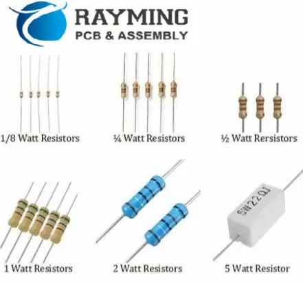
Resistors are electronic components that help in controlling the flow of electrical current in a circuit. They are passive components. It means they do not add any energy to the circuit, but rather they resist the flow of current. Simply put, resistors are typically made of a material with high resistivity. Such materials include carbon or metal, and their resistance is in ohms.

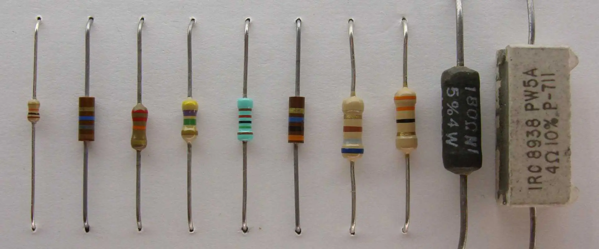
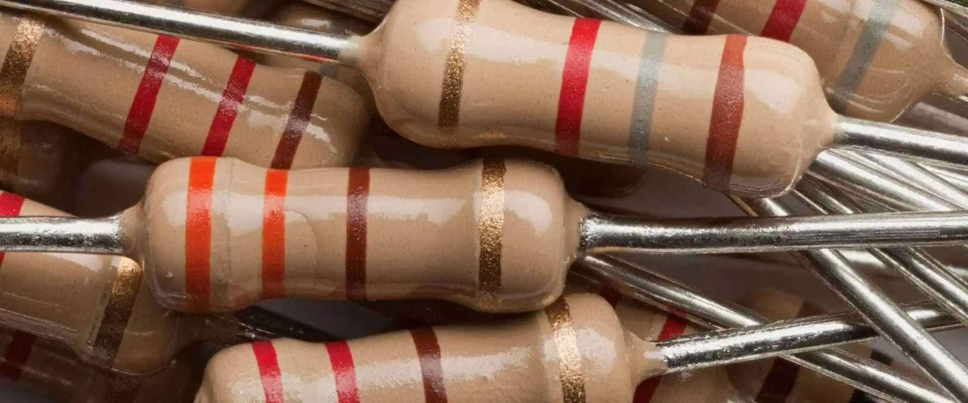
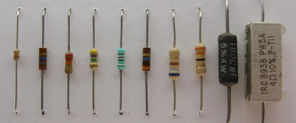
Set of colored bands that are painted on the body of the resistor indicate the value of a resistor. These bands represent the numerical value of the resistance. It shows the tolerance and the temperature coefficient of the resistor too.

For a 3.9K resistor, the colored bands would typically be brown, white, red, and gold. The brown band represents the first digit of the resistance value, which is 1. The white band represents the second digit of the resistance value, which is 9. The red band represents the multiplier, which is 1000 (or 10^3). The gold band represents the tolerance of the resistor, which is typically 5%.

Limitations of 3.9K Resistors

Zero Ohm Resistor

3.9K The limitations of a 3.9K resistor are like those of any other type of resistor. Here are some of the most common limitations:

1. Tolerance

All resistors have a tolerance, which is the degree to which their actual resistance can vary from their nominal (or rated) resistance. For example, a 3.9K resistor with a tolerance of ยฑ5% could have an actual resistance anywhere between 3.705K and 4.095K. This can affect the accuracy of the circuit and may require the use of precision resistors in some applications.

2. Temperature coefficient

The resistance of a resistor can vary with changes in temperature, and this variation is known as the temperature coefficient of resistance. A high temperature coefficient can cause the resistance of the resistor to drift over time, which can affect the accuracy of the circuit.

3. Power rating

All resistors have a maximum power rating, which is the amount of power they can safely dissipate without overheating and potentially failing. A 3.9K resistor with a low power rating may not be suitable for high-power applications, which could require a larger or higher-power resistor.

4. Frequency response

All resistors have a parasitic capacitance and inductance, which can affect their performance at high frequencies. A 3.9K resistor may not be suitable for use in high-frequency circuits, which could require specialized resistors with low parasitic capacitance and inductance.

5. Noise

All resistors generate a small amount of noise, which can be a problem in some applications where low noise is critical. A 3.9K resistor may not be suitable for use in low-noise applications, which could require specialized resistors with low noise characteristics.

6. Voltage coefficient

The resistance of a resistor can also vary with changes in voltage, and this variation is known as the voltage coefficient of resistance. A high voltage coefficient can cause the resistance of the resistor to drift as the voltage across it changes, which can affect the accuracy of the circuit.

7. Environmental factors

Environmental factors such as humidity, vibration, and radiation also affect the performance of 3.9K resistors. In some applications, such as in aerospace or medical devices, specialized resistors may be required to ensure reliable operation in harsh environments.

8. Cost

The cost of a 3.9K resistor can vary depending on its specifications, quality, and quantity. In some cases, the cost of a high-quality or specialized resistor may be prohibitive. You should consider alternative solutions too.

The limitations of a 3.9K resistor depend on the specific requirements of the circuit and the application. The designer or engineer must carefully consider the specifications and limitations of the resistor to ensure it is suitable for the task at hand.

Buying Guide of 3.9K Resistors

FULL PCB MANUFACTURING Quote

If you are in the market for 3.9K resistors, there are a few factors that you should consider ensuring that you are purchasing high-quality components that are suitable for your application. Here is a buying guide for 3.9K resistors:

  • The first thing to consider when purchasing a 3.9K resistor is its resistance tolerance. The tolerance indicates the maximum deviation from the stated resistance value that the resistor can have. For example, a resistor with a 5% tolerance can have a resistance that is up to 5% higher or lower than the stated value. Resistors with tighter tolerances are generally more expensive, but they offer greater accuracy in your circuit.
  • The power rating of a resistor is the maximum amount of power that it can safely dissipate without overheating or being damaged. When choosing a resistor for your application, you should make sure that the power rating is adequate for the amount of current that will be flowing through it. Choosing a resistor with a lower power rating than required can lead to overheating and potentially damage your circuit.
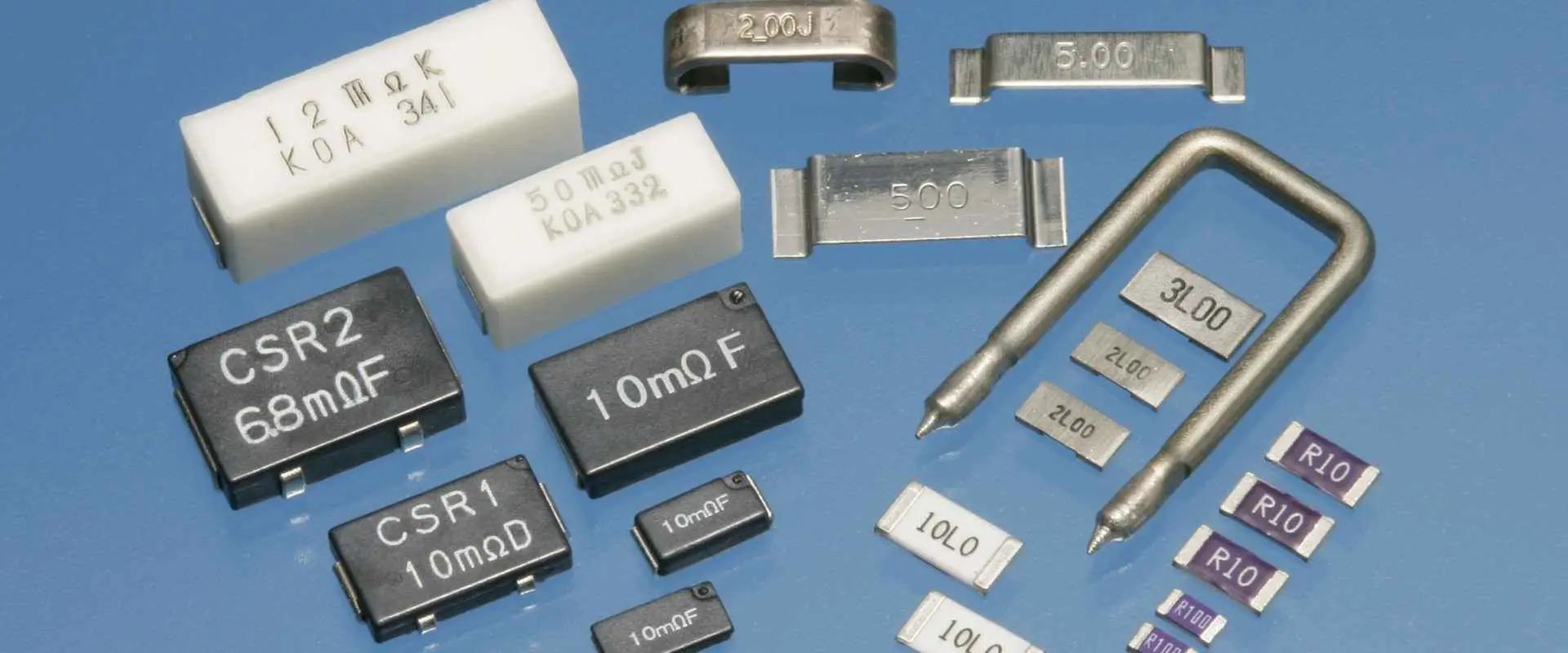
  • There are different types of resistors available, such as carbon film, metal film, and wire wound. Each type of resistor has different characteristics, such as their temperature coefficient, noise level, and stability. You should choose a type of resistor that is suitable for your application based on these factors.
  • The package type of a resistor refers to the physical form of the component, such as through-hole, surface mount, or axial lead. You should choose a package type that is compatible with your circuit board and can be easily installed in your application.
  • Finally, you should consider the quantity of resistors that you need to purchase. If you are buying a small number of resistors, you may be able to purchase them from a local electronics store. However, if you need a large quantity of resistors, you may be able to save money by purchasing them in bulk from a distributor or manufacturer.

Final Thoughts

We have articulated everything you should know about 3.9K Resistors. These resistors are high in demands and manufacturing mostly happens in China. We hope you have received a better insight into the uses and buying guide of 3.9K resistors.

Getting Excellent Outcomes in Electronic Devices Manufacturing

Electronic Devices Manufacturing

Manufacturing electronic devices is a complex process that requires a great deal of attention to detail. It’s a daunting task, but luckily, we have a fail-proof guide to help us get through it! From design to sourcing, assembly to packaging and shipping, this step-by-step guide will help you produce gadgets in no time! Notably, the process also comes with challenges, from sourcing raw materials to staying on top of ever-changing technology. However, by following the steps outlined in this article and implementing sustainable practices, manufacturers can ensure that their electronic devices are of the highest quality and meet all safety standards. Furthermore, this information will also delve into the current trends in the electronic manufacturing field.

Electronic Devices Manufacturing: Definition

Manufacturing electrical devices entail creating, fabricating, and assembling electronic parts to produce finished goods. This process covers manufacturing electronic components such as printed circuit boards (PCBs), microchips, resistors, capacitors, transistors, and integrated circuits. We must also develop software and firmware to govern how the gadget operates. Electrical device producers frequently use automated tools and procedures to create their goods, enabling efficient and precise production.

How is the Manufacturing Process of Electronic Devices?

Electronic Devices

The electronic device manufacturing process is lengthy and requires a lot of care. Therefore, you must follow a specific sequence to ensure you get the best out of your design and manufacturing process. The following guidelines give a brief overview of the steps to follow in the manufacturing procedure:

1. Design:

The design phase is the first step in the manufacturing of electronic devices. Engineers and other professionals provide their feedback when creating and designing the product at this stage. During the manufacturing process’s design phase, the engineers develop and produce the circuitry and components required for the device to operate as intended. Designing the device’s hardware, software, and firmware falls under this category. The engineers and other experts will also consider any environmental elements like heat, vibration, and electromagnetic interference that could affect the gadget and its performance at this stage.

2. Sourcing:

The next phase involves obtaining the parts needed to build the device when the design is complete. To do this, please carefully investigate the prospective suppliers, evaluate their products, and negotiate prices. Locating vendors who offer high-caliber goods at reasonable costs with consistent delivery schedules is crucial. Furthermore, choosing suppliers with a robust dedication to sustainability and considering the supply chain’s environmental impact is essential.

3. Assembly:

The following phase in the production process is assembly, which comes after sourcing all the components and materials. Using tools and equipment like pliers, screwdrivers, and soldering irons, you must physically assemble the device at this step. This iteration will involve installing them in the gadget and connecting components like chips and capacitors. In addition, you must test the product during assembly to ensure it adheres to the specifications.

4. Packaging and Shipping:

The product is now ready for packaging and dispatching once it has passed testing and approval. You now place the finished product in the proper packaging during the packaging process and then label the essential information on the product. This action helps safeguard the item during storage and transportation. The client or store receives the merchandise once you have dispatched it. In addition, the producer may also occasionally send the product to the customer directly.

5. Eco-Friendly Initiatives:

Many electronics producers have made efforts recently to lessen their environmental impact. Implementing eco-friendly initiatives is the last phase in the manufacturing of electrical devices. This iteration entails minimizing the production process’s adverse ecological effects by employing environmentally friendly materials and consuming less energy and waste. Manufacturers should also explore opportunities to recycle or reuse resources using renewable energy sources or recycled plastic for packaging. Additional environmentally responsible measures include printing with water-based inks, utilizing certified sustainable materials, and shipping with recycled packaging. By adopting eco-friendly practices, manufacturers can lessen their environmental effects and produce more sustainably.

Challenges Faced During Electronic Devices Manufacturing

FULL PCB MANUFACTURING Quote

The electronics industry is ever-changing, and manufacturers must keep up with the latest innovations and technologies to remain competitive. This necessity creates several challenges for electronics manufacturers, such as:

1. Access to Raw Materials:

The electronics manufacturing process requires access to a steady supply of raw materials. Commonly used materials in electronics manufacturing include copper, gold, aluminum, tin, and silver. These materials are often available from mines, whose locations can be in remote areas with limited access. Many of these materials are finite resources, and their cost may fluctuate significantly yearly. This action can create challenges for electronics manufacturers looking to procure the necessary supplies to keep their production lines running.

2. Quickly Changing Technology:

As technology advances, it can significantly affect how we manufacture electronics. In terms of the time, money, and expertise needed to apply them, new technologies can present problems and possibilities for manufacturers to enhance their production capacity. First, however, manufacturers must stay on top of shifting consumer demands and industry standards.

3. Pricing Competition:

Domestic and foreign rivals exert intense price pressure on electronic makers. So, for manufacturers to continue being profitable, their product costs must remain competitive. This necessity may make it challenging to manage expenditures, such as when attempting to lower labor and material costs while maintaining quality and safety standards.

4. Short Product Life Cycles:

In the electronics industry, short product life cycles can create challenges for manufacturers who must continuously introduce new products to remain competitive. This step calls for manufacturers to develop new products quickly and efficiently to keep up with the changing market. Manufacturers must also manage their existing products, which can quickly become obsolete or uncompetitive.

5. Environmental Regulations:

Electronics manufacturing is subject to several environmental regulations, which can create challenges for manufacturers regarding compliance. These regulations cover many areas, such as noise and air pollution, waste management, hazardous materials, and energy efficiency. Manufacturers must, therefore, comply with these regulations to protect the environment and avoid costly fines and penalties.

6. Supply Chain Disruptions:

Delays in manufacturing and lower profits might result from supply chain disruptions. In addition, natural disasters, labor disputes, political unrest, and other problems can contribute to this problem. Therefore, for electrical producers to lessen the effects of supply chain disruptions, it’s critical to have backup procedures in place.

7. Labor Issues:

Electronic Devices manufacturer

The electronics sector has traditionally needed help producing goods using human labor. However, several labor concerns have hampered the manufacturing process due to factors such as pay, working conditions, and the shortage of educated workers. Delays in the manufacturing process and a decline in product quality are the results.

8. Counterfeit Products:

In the electronics sector, counterfeit products are a significant problem. Unfortunately, spotting counterfeit goods can be exceedingly challenging, and producers frequently need help telling them apart from the real thing. This difficulty could result in a decline in product quality and financial loss for the maker due to having to pay for these fake goods.

9. Data Security Hazards:

With ongoing technology development, data security has become a significant problem for the electronics sector. Therefore, manufacturers must ensure their data is safe and out of illegal access. However, this step might be challenging because new technologies constantly develop, making staying current with the most recent security measures difficult.

10. Developing Markets:

The electronics industry can benefit significantly from emerging markets, but they also present significant challenges. High levels of corruption, a lack of skilled labor, and a lack of infrastructure are frequent characteristics of these marketplaces. Due to this, it may be challenging for manufacturers to create high-quality goods on schedule.

Trends In Electronic Devices Manufacturing

The electronic device manufacturing industry has seen tremendous growth over the past decade. This growth has resulted from technological advances, changing consumer preferences, and increasing demand for efficient and reliable products. The following are some of the latest trends in this manufacturing process:

ยท 3D Printing

The introduction of 3D printing is one of the most significant trends in producing electrical products. Manufacturers can now produce goods with more complicated geometries and sophisticated designs than ever before due to this technology. Faster prototyping and product testing made possible by 3D printing can also assist manufacturers in cutting down on development costs and time to market. Furthermore, 3D printing may help produce components applicable in various ways, enabling producers to develop goods for a broad range of needs.

ยท Portability and miniaturization

The growing need for portability and miniaturization also impacts the industry that makes electronic products. To meet this demand, manufacturers had to focus on creating more lightweight and compact products. One of the best examples of a technology that has progressed miniaturization is microelectromechanical systems (MEMS). Producers may now develop lighter and smaller components that can be helpful in various ways thanks to MEMS technology. In addition, miniaturization advances have also made creating devices with higher energy efficiency and longer battery lives possible.

ยท Internet of Things (IoT)

The Internet of Things (IoT) devices allows manufacturers to gather and analyze data from numerous sources, including sensors, to increase the efficiency and precision of the production process. Afterward, this information can help optimize production and cut expenses. Also, producers may now utilize IoT gadgets to monitor their goods and make sure they are working correctly.

ยท Virtualization

Virtualization is becoming increasingly significant in the electronic devices manufacturing industry that produces electrical gadgets. With the help of this technology, the manufacturer can easily virtualize the entire manufacturing cycle from design to assembly. Before going into production, this virtualization enables manufacturers to test and improve their products in a virtual setting. Moreover, virtualization enables faster data access and sharing for manufacturers and better collaboration with other businesses.

Conclusion

Electronic device manufacturing is a challenging feat. It is, therefore, essential to consider the various challenges associated with it. It takes work, from sourcing suitable materials to staying ahead of the latest trends. Nevertheless, it is a gratifying process that can result in fantastic gadgets. Despite its complexity, producing electronic devices is essential to advancing our modern society, and producers should be proud of their accomplishments. Combining suitable materials, technologies, and strategies is necessary to imagine the possibilities in the electronic field. So, don’t be afraid to take a risk and get creative – who knows, you might create the next revolutionary device!

Factors to consider before chip on board manufacturing

chip on board manufacturing

Directly mounting a bare semiconductor chip onto a printed circuit board (PCB) and wire bonding the chip to the board constitutes the process known as a chip on board (COB) production. Reduced package size, higher electrical performance, and lower cost are just a few benefits this technology has over conventional packaging solutions. Yet to ensure successful production, it’s crucial to consider several criteria before starting a COB manufacturing process. Therefore, this article will discuss the crucial elements to consider before beginning a COB manufacturing process.

Board Restrictions

When designing a printed circuit board, we must consider board restrictions such as board size and shape. We must first make sure the circuit has enough room. The size and functionality of the finished product are just a couple of the variables that impact the size of a circuit board. Electronic devices are getting smaller and more versatile due to technological advancements and shifts in consumer demand, which also significantly impacts PCB design. Hence, estimating the PCB sizes is essential before beginning the design. If there isn’t enough room, a multi-layer or high-density interconnect (HDI) design might achieve the needed functionality.

In terms of shape, we typically design the PCB into a rectangle. Nevertheless, the PCB must be created into a specific shape for some items with irregular shapes, even though doing so will increase the cost. We must consider the number of layers early in the PCB design process. Although designing a PCB with additional layers costs more, it enables us to design a PCB with more sophisticated features.

Quality Control

chip on board

Chip-on-board (COB) manufacturing requires quality control to guarantee that the finished product meets electrical and mechanical requirements. Chip installation, wire bonding, encapsulation, and testing are some of the assembly processes essential in COB production. The performance and dependability of the finished product depend on each of these phases.

We can produce a defective product that might not function properly if you do not appropriately carry out any of the phases in the COB manufacturing process. Products with flaws can result in serious issues like decreased performance, system breakdowns, and sometimes even safety risks. Before the delivery of the finished product, quality control assists in finding and fixing any errors.

Several factors highlight the significance of quality control in COB manufacturing:

Component Selection: In the manufacture of COBs, the choice of proper components is crucial. Thanks to quality control, only top-notch components are utilized, lowering the likelihood of failure and ensuring the dependability of the finished product.

Process Control: Manufacturing COBs is a lengthy and intricate assembly procedure. Each process correctly happens, and quality control ensures the finished product satisfies the requirements.

Testing: In manufacturing COBs, testing is a crucial aspect of quality control. It must undergo extensive testing to verify that the finished product satisfies the necessary electrical and mechanical requirements. Functionality, performance, and reliability testing are part of this.

Traceability: Quality control also supports Traceability throughout the COB production process. This entails documenting each component and assembly phase, making it possible to identify the root of any flaws or issues.

Continuous Improvement: The purpose of quality control in COB production is to continuously improve the manufacturing process and the quality of the finished product. This includes determining the source of any difficulties, fixing them, and making enhancements to prevent similar problems from occurring again.

Environmental Considerations

FULL PCB MANUFACTURING Quote

When it comes to making COB devices, it’s essential to think about the environmental impacts. Chemical usage involves stuff like acids, bases, solvents, etc., that can be harmful, so handle and dispose of them carefully. Energy-wise, a lot of energy is helpful in the process, so consider energy-efficient equipment and renewable sources to reduce that. Waste-wise, there’s lots of waste created, so recycle and reuse materials, and mitigate disposable material use. Water usage is also a consideration, so reduce it where you can and ensure you treat wastewater correctly. And lastly, materials โ€“ use sustainable, recyclable, and non-toxic ones. All this can help minimize the environmental impact of COB devices and make for a more sustainable future.

Assembly Process

Many assembly procedures create integrated circuits before chip on board (COB) manufacturing (ICs). Some of these procedures include wafer fabrication, photolithography, etching, depositing, dicing, packing, and assembly onto a printed circuit board (PCB). Making silicon wafers, which will serve as the ICs’ substrate, is known as wafer fabrication. A mask is helpful in photolithography to transfer a design from a surface to a silicon wafer. Etching involves scraping away undesirable material.

Deposition entails covering the wafer with a thin layer of metal. Next, we dice the wafer into tiny squares containing one integrated circuit. Finally, we package individual integrated circuits (ICs) into ceramic or plastic packages. Directly mounting the ICs onto the PCB and wire bonding them to the necessary areas of the board constitute an assembly. This method enables high-density packaging and has numerous potential uses.

Wire Bonding

Bonding for HDI PCBs

Wire bonding creates electrical contact using small wires and various parameter combinations, including pressure, heat, and ultrasonic wave. We classify it as a solid-phase welding procedure in which an intimate interaction occurs between two materials. One may use the bonding force that may cause the material to deform, making rough surfaces more smooth and separating the contaminant layer. In a year, more than 4 Tera wires bond, most of which are helpful in over 50 billion ICs (incorporated circuits). Along with the older wire bonding approach, several bonding methods are ideal, including Flip-Chip, Tape Automated Bonding (TAB), and Controlled Collapsed Chip Connectivity.

Two common wire bonding types are Ball and Wedge bonds. Wire bonding methods start by joining the bottom of the chip with a chip carrier utilizing natural conductive glue or solder.

Precautions to take when handling COB

Iterative PCBA development is a method for raising quality. Boards must be treated carefully during the manufacturing, production, and storage phases to obtain the highest possible quality. Development precautions include preventing copper traces in the air, utilizing the proper surface finish, eliminating remaining debris, wearing protective gear, being cautious when using equipment, and preventing humidity. Using the right equipment is essential when working with tiny boards since the risk of damage is greater. Moreover, contaminated boards might exhibit inconsistent behavior, making precise testing challenging.

Summary

Chip on Board (COB) manufacturing generally entails wire bonding the chip to the board and directly mounting a bare semiconductor chip onto a printed circuit board (PCB). Therefore, several aspects, including chip selection, PCB design, wire bonding, the assembly process, quality control, and environmental considerations, must be carefully considered while manufacturing COBs.

To ensure that the finished product matches the necessary criteria, wire bonding, a crucial phase in the COB manufacturing process, must be appropriately managed. In addition, chip-on-board (COB) manufacturing requires quality control to guarantee that the finished product meets the necessary electrical and mechanical requirements. Regulation compliance, sustainability, resource conservation, waste minimization, energy conservation, and packaging are all significant environmental factors in COB manufacturing.

It is possible to develop high-quality, dependable COB products that adhere to the necessary specifications by carefully considering these elements.

What should you expect when Dealing with PCB Design Quotes

PCB design

The PCB development life cycle is long and complex. However, one of the major phases in this development life cycle is known as the PCB design phase. During this phase, you will have to develop a blueprint that has all the information required to create your printed circuit board. That means you’ll have to bring out the board’s circuitry, the materials to generate the board, the number of layers that the circuit board will have, and so much more. Though mostly overlooked, this phase is usually crucial to the development life cycle of the circuit board. If you mess up at this stage, you might end up generating a faulty circuit board at the end of the manufacturing process.

However, to avoid this situation, some people choose to work with a professional with impeccable experience in generating circuit board designs. These experts use their resources and expertise to produce high-quality, optimized printed circuit board designs. However, to work with these experts, you have to first fill up a PCB design quote for them to utilize. The PCB design quote will provide the necessary information regarding your project’s cost and time requirements. However, the quote entails more than just this information. So what exactly is a printed circuit board design quote? What does it contain? And why should you take it seriously?

PCB Design Quote in a Nutshell

A printed circuit board design quotation is a rough estimation of the time, cost, and capability of your manufacturer in terms of developing your PCB design. Moreover, quotes are not only crucial for the designing phase, but they are also ideal for the manufacturing and assembly phases.

However, the PCB design quote doesn’t only favor the client. It also helps the PCB designer in terms of generating accurate designs that meet user expectations. Therefore, when filling up design quotations, you should ensure that you fill in all the necessary information in an accurate manner.

The details you provide in a PCB design quote are paramount to your board’s design process. Your PCB designer will only be able to generate an impeccable and functional design if you provide them with accurate information that isn’t ambiguous.

To get a printed circuit board design quotation online, you must visit the website of a renowned printed circuit board designer or manufacturer. They usually post their quotation forms online for clients to fill out and send.

 What can you expect to fill in a PCB Design Quote?

Printed circuit board design quotations will ask for crucial information such as:

Information about the Client

Printed circuit board design quotes will typically ask you to fill up some personal details, which will include:

  • Your full name
  • Your email

Moreover, the form will also ask you to fill up some details regarding your company. These details will include the following:

  • The name of the company
  • The current location of the company
  • A phone number that the manufacturer can utilize to contact the company or you in particular

Information regarding the Project

FULL PCB MANUFACTURING Quote

A printed circuit board design quote will also ask you to fill in the information regarding the project you want done. Here you will find a field that will ask you to select the service required, and under this, you will find options such as:

  • Designing a new PCB from scratch
  • ECO of an existing printed circuit board layout
  • Consultation regarding DFM of a current PCB
  • Auto routing of an existing PCB
  • Panel design
  • Schematic entry

You can select the service you want done for you under these options. Moreover, you will also find another field asking you to state the desired turn-around time for your project. In this field, you must fill in the time you want your project completed.

Another required field you will find is the “type of design” field, often in options forms. The main options that you will find are the following:

  • PCI Card
  • DDR Module
  • VME BUS style PCB
  • CPCU 6U style PCB
  • CPCI 3U style PCB
  • Flexible PCB
  • RF PCB
  • Microprocessor PCB
  • Low-level analog PCB
  • Standard PCB having mixed circuitry

Under this field, you must choose the type of circuit board design you want your PCB designer to utilize. After selecting the design type, you then have to move on to the next option field, which will ask you to choose the kind of schematic that you want utilized on your PCB design. Then under this, you will find schematic options that include:

After this option, you might then find another options field labeled “printed circuit board footprint to be made by your designing company.” Under this options field, you will find options such as:

  • Most printed circuit board footprints have to be created โ€“ which indicates 50% and more
  • Minimal Printed circuit board footprints have to be created โ€“ which implies a 5%
  • Some printed circuit board footprints have to be created โ€“ which means 15%
  • All printed circuit board footprints are common, and therefore none should be created
  • A file or library containing all printed circuit board footprints will be provided later

Components

PCB Layout in KiCA
PCB Layout in KiCA

Under the “total number of electrical components on your circuit board design” options field, you must select the number of electrical components you want on your design. Here you can choose anything between 1 to over 1250 components.

Moreover, these forms will also ask you to indicate whether or not your PCB design will require special components, for example:

It will also ask you to fill in details regarding any special routing on your PCB design.

Other Crucial Details

Other than the crucial information specified above, a PCB design quote will also ask you to fill in the following:

  • The Printed circuit board’s overall thickness
  • The layer count
  • Units
  • The overall X and Y dimensions of the board

These are the main details you must fill in a PCB design quote.

Conclusion

A printed circuit board design quote is vital to the successful designing of a printed circuit board by a PCB designer. The information you provide in this form offers crucial details that the designer utilizes to generate the PCB design according to your needs. Therefore, you should fill this form with much care and attention.

What is a Populated Circuit Board?

Subcontract PCB Assembly

A pcb containing electronic components is called a populated circuit board. A bare or empty board is one that doesn’t have any installed electronic components on it. A PCB could therefore be either populated or bare. Surface-mount technology as well as thru-hole technology can be used to populate PCBs.

A PCB assembly is just like the populated circuit board. These board’s components are called surface-mount devices. Electrical equipment which links electronic components is known as  the populated Circuit board. This PCB has conductive tracks, pads, and other features.

To create the populated Circuit board, manufacturers solder all electronic components to the board. IC, diodes, and capacitors are some of the components found on the populated circuit board. Bare boards lack electronic components, but a populated Circuit board does.

It’s critical to recognize the distinction between a populated Circuit board and PCB manufacturing. This creation of bare boards is a step in the PCB manufacturing process. PCB prototypes are made throughout the production process. The way a PCB is filled depends on a circuit board’s intended use.

Techniques for Populated Circuit Boards

Manufacturers employ two main methods for PCB population. These methods include through-hole as well as surface-mount technology. A circuit board can be populated using THT and SMT.

SMT

SMT can be described as a typical method of populated circuit boards. Manufacturers mount delicate components using SMT. The components in the surface-mount technology have short leads. Additionally, this method populates components on the circuit boards using automated machinery.

Direct SMD mounting on the Circuit board is known as SMT. Manufacturers utilize pick – and – place machines to populate the circuit board.

THT

The components’ pins are inserted into the board’s holes using thru-hole technology. Component placement in this case needs to adhere to THT process requirements. This method is used by manufacturers to position a component present on circuit boards.

Manufacturers, however, insert components containing leads through plated through hole in THT. Before the invention of SMT, this method of filling boards was widely used.

Factors Affecting Populated Circuit Boards

FULL PCB MANUFACTURING Quote

While populating the blank board, manufacturers need take a few things into consideration. Some elements have a direct impact on the process of the populated circuit board.

Part size

The size of the electronic parts on circuit boards varies. The size of the components must be taken into account by the manufacturer when choosing the process speed. The pick as well as place device will adjust for part size.

The placement speed

The process of PCB population entails attaching components to the bare circuit boards. There are many processes involved in this aspect. Reducing the amount of processes will speed up placement for manufacturers. For instance, if components are pointing in the same direction, you can position them without rotating them.

Board types

PCBs come in a variety of forms. How you should populate it will depend on the type of board. A multilayer circuit board will have a different population than the single layer type.

Advantages of Populated Circuit Boards

A filled PCB comes with many benefits. It is crucial to understand that populated PCBs are what are employed in the production of electronics. In the absence of electronic components, the bare PCB is inoperable. In modern electronics, populated circuit boards are crucial.

Compact style

A small design is produced by mounting the electronic components onto the board. So the PCB designer could try to create a fantastic design when filling a PCB. Connecting the components as well as enabling input and output connections are populated circuit boards.

Less electrical noise

In circuits, there seems to be a possibility that electronic noise could occur. The components are mounted by the Circuit board manufacturer to minimize the electronic noise generated by a circuit. Path lengths can be shortened by populated PCBs to cut down on electromagnetic emission.

Loose connections absent

When connecting components on a Circuit board using copy tracks, sloppy connections are probably going to be an issue. However, if such connections are made correctly, you probably wouldn’t bother with this.

Repair is easy

One advantage of the populated Circuit board is this. Any board flaw can easily be tested for and found. As a result, producers can quickly spot a defective component then replace it. This can be done without affecting other electronic parts of the circuit board.

Populated Circuit Board Applications

An extensive variety of applications frequently make use of populated circuit boards. There are versions of this board for most modern gadgets. This board can be utilized by our electronic industry to create electronic products.

The Military

In military equipment, the populated circuit board is frequently employed. The increased military industry’s demands are being met by these boards. In military equipment including missile detection units, the populated circuit board will be found. However, producers create populated circuit boards of high frequency for use in the military.

Consumer Electronics

The populated circuit board is seen in consumer devices including TVs, remote controls, and more. The core of all these devices are the populated circuit boards. They provide these devices with mechanical and electrical support. Connected boards that have been populated also aid in the creation of laptops and Cellphones.

Industrial System

The high-end industrial machinery have populated circuit boards. Among other things, printers, vending machines, and surveillance systems all use populated Circuit boards. Industrial boards need to be both mechanically and electrically sturdy.

Medical industry

There are more and more populated PCBs being used in the medical sector. These circuit boards are excellent for tracking diagnosis, therapy, and other procedures. These boards can also be found in ultrasound scanners, CAT, as well as other medical equipment.

Aerospace

Populated circuit boards are also used in the aircraft sector. Inside this application, the high-frequency as well as high-speed boards are used. They are much more susceptible to challenging circumstances, which explains why. This PCB is used in aerospace technologies like radio communication, satellites, and aircraft.

Pressure sensors as well as accelerometers are examples of monitoring equipment used in the aircraft sector. These tools aid in tracking an aircraft’s activity.

Conclusion

This electronic industry places a high value on the populated printed circuit boards. This board has several uses and is extensively used. They act as the foundation of a whole lot of electronic devices.

What you need to know about Embedded IoT?

embedded iot

The swift advancement of technology has caused a merging of boundaries among various fields, especially in the domain of IoT embedded systems, where the labels IoT & embedded systems have been intermingled to denote the same thing. However, even though some resemblances exist, an embedded system & IoT are distinct concepts. 

The inception of embedded systems dates back to 1965 when Autonetics, a company, created a miniature computer for employment in a missile navigation system. 

Embedded systems are independent devices typically engineered to perform a particular function. An Internet of Things embedded system, on the other hand, is the embedded system that is also internet-enabled, enabling it to exchange information with other Internet of Things embedded systems. 

Internet of Things embedded systems encompass our surroundings, including

  • Set-top boxes
  • POS terminals
  • Various medical devices
  • Smart appliances such as refrigerators, bicycles, and fitness trackers
  • Parking meters
  • And more

This article will comprehensively examine embedded systems for IoT devices. It will cover what an embedded system for the Internet of Things entails, its benefits, and practical applications. 

Distinguishing between IOT & embedded system appliances

Let’s examine the contrast between these two expressions:ย 

What is IoT system?

embedded system & IoT

Nowadays, “smart” appliances can connect to the internet and other appliances to facilitate routine tasks. For instance, a smart refrigerator can detect its contents, including expiration dates, and relay this information to its owner. This represents a standard use case of IoT in daily life.

What is an Embedded IoT system?

The embedded system is a small-scale computer developed for a particular function. It typically contains a microcontroller or microprocessor, the integrated circuit comprising memory, processor, & I/O peripherals on a single chip. 

The essential characteristic of the embedded system is its ability to execute digital processing. This sets it apart from virtual hardware devices that solely comprise circuitry and perhaps a battery. 

Embedded systems frequently feature sensors that enable them to monitor environmental variables. 

Difference between IoT and Embedded IoT

While an embedded system may not necessarily possess internet connectivity, an IoT(internet of things)embedded system does. The distinction between an embedded system and IoT is that an embedded system can be part of IoT. Embedded systems predating IoT did not have internet connectivity, making IoT(Internet of things) embedded systems typically inclusive of a wider variety of appliances and use cases.

What is an embedded system in IoT?

An IoT(Internet of things) embedded system is an embedded system with an internet connection. Another term for an IoT(Internet of things) embedded system is the “smart” application. A device does not require a touchscreen or keyboard to qualify as an IoT(Internet of things) embedded system, although such peripherals can be added.ย 

Types of Embedded IoT

FULL PCB MANUFACTURING Quote

An IoT-embedded system requires software to execute its intended purpose, which can take the form of either firmware /an embedded operating system. The software serves as the enabling factor for the IoT (Internet of things) embedded system to establish communication with other IoT-embedded devices.

In embedded systems, the phrases “embedded devices” and “embedded systems” are often used interchangeably, but embedded devices are typically components of a more extensive embedded system geared toward IoT applications. To distinguish between the two, an embedded device is a specialized piece of hardware designed to fulfill a singular or limited set of functions. These Single Purpose Appliances or Dedicated Devices are part of IoT(Internet of things) embedded systems crafted to execute a specific program or task unique to a specific business. 

Instances of IoT(Internet of things) embedded systems that are designed for a sole function include:

  • Kiosk devices
  • POS Solutions
  • Self-checkout systems

IoT embedded systems are extensively utilized in various industries, including retail, automotive, consumer products, healthcare, and others.

The contrast between IoT & Embedded IoT systems

In a single word, the disparity between IoT & embedded systems is “connectivity.” An embedded system can include a pacemaker, for instance, but when the device is enabled to communicate with the external environment, such as transmitting heart rate data to the central database, it transforms into an IoT(consumer products) embedded system

Another contrast between the embedded system & IoT(Internet of Things) is that IoT pertains to a group of devices that characterize the newly interconnected world. In contrast, the embedded system pertains mainly to the hardware employed in these applications.ย 

The primary differentiation between the embedded operating system & IoT is that the Internet of Things (IoT) operating system must facilitate connectivity. The capacity for networking IoT embedded system appliances is what sets them apart from regular embedded systems. 

Each IoT application involves the embedded system as an integral component, which is why it is called an IoT embedded system. The embedded system is created initially, and then features are added to transform it into an Internet of Things (IoT) device. 

Embedded systems, such as robotic systems in manufacturing/data warehouses, can be highly complex in their own right. However, unless the application can communicate & establish connectivity with other IoT (Internet of Things) embedded systems, its role as a standard embedded system will be limited to its sole intended purpose.

The difference between an embedded system & the IoT embedded system lies solely in its capability to communicate.

The importance of Embedded IoT

To better understand the difference between an embedded system and IoT, it could be helpful to examine some real-world use cases. Here are a few examples that further clarify the contrast between an IOT and an embedded system.

To comprehend the contrast between an IOT and an embedded operating system, it is essential to note that both IoT(Internet of Things) embedded system appliances and non-IoT embedded system appliances rely on some form of software to function, whether it is firmware, bootloaders, drivers, or a comprehensive embedded operating system.

Merely being an IoT( Internet of Things) embedded system does not necessarily require a complete operating system, though it is typically the case. Appropriate Rating systems are appropriate for use in some embedded systems, such as Linux / Android.

By installing specifically modified versions of Android on the Internet of Things( IoT )embedded system, the appliance will be capable of:

  • Obtain OTA updates
  • Enjoy the benefits of Mobile Device Management, such as remotely managing an IoT( Internet of Things) embedded system. 

Android is a suitable operating system for IoT( Internet of Things) embedded systems. In addition, the introduction of the Raspberry Pi has made mass production of IoT( Internet of Things) embedded systems much more accessible, particularly after the release of its Generation 3 models that include built-in Bluetooth & WiFi connectivity. By installing Android on your Raspberry Pi 3 B+, the IoT(Internet of Things) embedded system can access Raspberry Pi Fleet Management features (like MDM) mentioned earlier.

Top Benefits and Characteristics IoT Industry 4.0

Smart Manufacturing IoT

The industry of manufacturing is gaining rapid popularity due to using advanced equipment and technologies like Machine Learning, the Internet of Things, and Artificial Intelligence. Digital advancement has remarkably enhanced the productโ€™s quality and significantly reduced the runtime of machines and processes. However, the industry of automation and the IoT is playing a significant part in this method.

The Industrial IoT has brought immense changes and transformations recently with its great benefits in the applications. It hugely contributes to the improvement of work efficiency and workflow within the factories through real-time management and controlling the process and assets altogether. The benefits that IIoT brings to us could be used significantly to make the industry better.

The benefits or opportunities that IIoT brings include Process Optimization, Automation In Factories, Performance Monitoring, and Intelligent Manufacturing.

IoT Industry 4.0

Industry 4.0 is an industrial revolution. Its main aim is to make the industry smarter by using advanced IoT technologies like automation, interconnectivity, exchange, and data monitoring in real time. Industry 4.0 is fully devoted to customers, doing its best to help the manufacturers in providing quality customer services and experience. The customer-devoted strategy of IIoT or Industry 4.0 covers product sales, product visioning, assembly, service management, and manufacturing. However, IoT plays a vital role by constantly helping the manufacturer with the needs and demands of the customers.

Evolution of IoT Industry 4.0

Industrial-IoT-Devices

IoT is the sole reason for the rapid development of Industry 4.0. Industry 4.0 is responsible for making connected everything within a shared network and allows the automation process of all operations, which reduces the effort and time of human resources. Data monitoring in real-time improves the process of decision-making while predictability protects the industry from future dangerous events and supports asset management for workability in the future.

The major stages of Industry 4.0 and IoT evolution includes generating insights, connecting things, innovation, and optimizing process and operations.

The main aim of IoT is to make things way smarter and internet connective no matter if it is home, office, building, hospital, or industry. While Industry 4.0 specializes in Augmented Reality, Cybersecurity, Digital Twin, Autonomous Robots, Connected devices, Big Data, Heavy machinery, and Cloud Computing. However, the primary points of IoT and Industry 4.0 are Heavy machinery, Smart plant grids, and Connected Devices. IoT leads towards the excellence of manufacturing by taking crucial and essential parts in almost all activities of industry and enhancing its efficiency. IoT technology is ideal for industries as it provides beneficial results by combining operational technology and information technology for operations and processes.

From Stream To Sensor: IoT Industry 4.0

FULL PCB MANUFACTURING Quote

ยท First Industrial Revolution:

The first massive industrial revolution came in Britain in the 18th century. It was the time when it helped in mass production with the help of steam and power rather than using animal and human power. However, the products are manufactured by machines instead of manually by human hands.

ยท Second Industrial Revolution:

The second wave of the industrial revolution hit after a century. It introduces oil usage, assembly lines, and electric and gas power. Other than these phenomenal power sources, other advanced ease of communication were also introduced, like the telegraph and telephone, which helped in mass production and automation of manufacturing techniques to some extent.

ยท Third Industrial Revolution:

In the 20th century, the third industrial revolution hit, which brought data analysis, advanced telecommunications, and computers into the manufacturing process. The process of digitization has been introduced in the factories by integrating PLCs into manufacturing machines to advance the automation process and transfer data here and there.

ยท Fourth Industrial Revolution:

Currently, we are living in a fourth revolutionary era of industries which is also called Industry 4.0. It enables automation of the process of manufacturing, making factories and machines smart, and analyzing the production data, which helps in producing quality and efficient products. With industry 4.0, flexibility is enhanced, which lets manufacturers provide customized products meeting the demands of customers. This leads to efficiency in many sectors. Moreover, combining the operational data of different floors in one system enables the smart factory to make better decisions.

Characteristics Of an IoT Industry 4.0

Data Analysis

Interconnected machinery and integrated sensors generate a considerable amount of information for manufacturing industries. Data analytics aids manufacturers in analyzing historical trends, recognizing patterns, and making reasonable decisions. Smart factories also take data from other areas of industry and their ecosystem of distributors and suppliers to produce deeper insights. By taking a look at data collected through human resources, warehousing, or sales, manufacturers can make decisions about productions solely based on personnel and sales margins. An exclusive representation of operational digitization can be made as a digital twin.

The Benefits Of IoT Industry 4.0

There are various ways of integrating IoT into factories and their manufacturing process. Here are some beneficial points of integrating IoT in the factories.

ยท Data collection & automation

Automation and Data collection are one of the best features of integrating IoT in the manufacturing factory. IoT gathers data on all aspects of the manufacturing process and provides remote commands. This helps in enhancing production and its efficiency and increases the output while reducing effort, time, and expense.

One best example of IoT is integrating internet connection ability in the PLCs. This analyzes the data of the manufacturing process thoroughly and immediately reports to the producer if anything goes wrong. They also give permission to change parameters remotely at any time, which helps managers to correct the inefficient component in the assembly.

The workflow of the customized motorbike of Harley-Davidson is a real model of how the Internet of Things has developed manufacturing efficiency. In 2016, the manufacturers of this motorbike installed IoT devices and sensors in the machines of their factories to identify the speed limit of work. Well, they gathered data that reduced the time of manufacturing by up to 6 hours. And they saved up to $200 million in this process.

ยท Data Security

The primary security problem in the management of data for businesses is human error. BakerHostetler’s report back in 2018 shows that humans were the main reason for most cybersecurity incidents that they had managed. Among those incidents, the ratio of cases that were caused by employees was 17% which led to data breaches.

However, integrating IoT in the management of business helps in improving the management and reduces the number of humans managing the data manually. This is because IoT allows one to monitor, send or receive reports remotely through an automatic system without going through reading all emails all day.

In simple words, IoT reduces the time human users interact with data which automatically reduces the risk of human errors.

ยท Predictive Maintenance

The runtime of one hour of manufacturing machines costs millions. In the manual process of manufacturing, staff members have to look around all the time in search of whether the machine is working properly or not. If not, then find the solution to it, which also adds up to the expense.

IoT applications significantly reduce the downtime of machines by providing predictive maintenance. With smart sensors and AI integrated into all machines, manufacturers can closely look at the health and stability of the machines. It notifies the team of maintenance right away if there is a slight fault that occurs before getting things any worse. This not only helps in reducing the downtime of the machine but also makes it stay longer.

Predictive maintenance helps manufacturers in saving a lot. According to the U.S. Department of powerโ€™s data, enforcing predictive measures leads to a reduction of breakdowns by up to 70-75%, maintenance cost by up to 25-30%, downtime by up to 35-45%, and return the investment in ten folds.

ยท Workplace Safety

By using unique and advanced technologies, IoT also improves the security level at the workplace. Smart sensors integrated at every manufacturing floor provide the manufacturer with constant feedback with the latest details and information. If any incident happens, the alarm system alerts the facility while stopping the machine and dispatches the maintenance team to reduce the risk of injuries.

Wearable devices with IoT also protect the workers. For instance, a smart band consists of sensors for pressures that can warn the workers of areas with a loud noise that can damage hearing. Same as augmented reality spectacles help in analyzing areas that could be dangerous and hazardous for workers.

Smart, hard hats are one of the live examples of this. It is a product of two companies’ collaboration. These hardhats with various features can sense the location of the user, humidity, temperature, and heart rate. These hardhats warn the workers if their vitals get low and if they are near getting heatstroke. Moreover, it also warns users of dangerous areas by vibrating or sound emitting.

IoT Industry 4.0 is Not The Future; It Is The Present

IoT devices are already getting popular among manufacturers, and they will not stop here but grow faster. As it directly benefits efficiency, cost, and risk management, it would be a loss if any manufacturer would not have IIoT in their factories.

How Is A 2.2K Resistor Different from Other Resistors?

Resistor color

2.2K ohms resistors are very popular in the electronic industry. These resistors are also known as axial-lead resistors. You can confuse these resistors with other resistors due to your less knowledge. They have unique color codes, so it is easy to recognize them. Start from the basics for a better understanding of the 2.2K resistor.

What Is a Resistor?

 Resistor is an important part of any electronic circuit. It has different uses. Its most important functions are to lower the current flow and divide the voltages. It can also block the transmission signal also. Resistors are also different types. Every resistor has different resistance and serves a different purpose. Thatโ€™s why you cannot put a specific resistor in every circuit design.

What Is A 2.2K Resistor?

‘K’ stands for one thousand ohms. So, 2.2K resistor means it has a value of 2.2000 ohms. It can also be said to have a value of 2.2K. A 2.2K resistor has multiple uses. It is a passive device, but it allows designers to design the circuit as they want to. In simple words, it gives you control over currents and voltages.

How To Recognize The 2.2K Ohms Resistors?

FULL PCB MANUFACTURING Quote

Each color band on the resistor has a specific meaning. It has at least two digit bands, one multiplier band, and one tolerance. This is the structure of a four-band resistor color code.

If your 2.2K resistor is a 4-band resistor, then the first three bands are normally red in color and give normal values, while the 4th band is the tolerance band of the resistor. Tolerance bands have different tolerance according to the color code.

 Similarly, five and six-band 2.2K resistors are also available in the market. Six band resistors have one extra band, which is the temperature coefficient. This is an indication of how sensitive the resistor is to temperature changes.

How To Read the Four-Band 2.2K Resistor?

 Many people find it difficult to read the color code of the resistor. They don’t understand the values of each band. Color lines on the resistor are not for decoration purposes. Every resort has a significant color code.

The color code of the 2.2K resistor is Red-Red-Red-Gold. Resistor color codes consist of digits followed by a multiplier and a tolerance value. Four-band resistors have two bands for digits. Each band on the resistor has a specific value. The first two bands are red in color. Therefore the digits from band one and band two are 2 and 2. Band Three is a Multiplier band. It takes the digits and multiplies them by a value of this band. Band Four is the Tolerance band. It gives the value of the tolerance for the resistor. So it’s not hard to read the color code of any resistor.

Advantages Of 2.2K Ohm Resistor

Resistor Wattage

The following are some advantages of the 2.2K resistor.

ยท Better Temperature Stability

Temperature stability is necessary for the proper and efficient working of resistors. 2.2K resistors have better temperature stability, so they work well even in harsh environments.

ยท Lower Noise

Sometimes noise becomes a problem when dealing with resistors. 2.2K resistor is the solution to this problem, so go with it. If you want to lower the noise in the circuit, the 2.2K resistor is ideal.

ยท Better For High Radiofrequency Applications

Sometimes opting for a good resistor becomes a problem when you are working with a complicated circuit. 2.2K resistors go well in high-frequency devices and applications. These resistors serve their purpose well. So if you are into high-frequency devices, then you must go for a 2.2K resistor.

ยท Low Cost and Easy Availability

 Cost is a matter of concern in circuit making. Low Cost is the advantage of a 2.2K resistor. The 2.2K resistor is one of the most affordable resistors available in the market. It is an ideal choice for budget-conscious electronics projects. It is also very easy to find, as it is widely available from many different suppliers. This makes it a great option for those needing to purchase bulk resistors. It is also a great choice for many newbies in the electronic world.

ยท Ensures A High Degree of Safety And Reliability

The 2.2K resistor helps to protect other components in the circuit from damage due to excessive current. This makes it an ideal choice for projects that require a high degree of safety and reliability.

Tips For Using 2.2K Resistors in Circuits

 The following tips will help you to design the best circuits while using a 2.2K resistor.

  • Verify the resistor’s tolerance before putting it into the circuit. Make sure the resistor’s tolerance is acceptable for your circuit’s requirements. Sometimes you use a very high resistance value resistor, and it ruins your circuit.
  • Environmental changes can affect the functions of resistors. So whenever you put the 2.2K resistor in the circuit, then keep the environmental factors in mind. Things like high heat, humidity, or other environmental conditions have effects on performance. Many people neglect environmental factors. In my opinion, humidity, and heat are both culprits in most circuit failures.
  • Always buy 2.2K resistors and other electronic components from a reliable vendor. If you don’t consider it, then low-quality resistors can affect the proper functioning of the circuit. A low-quality resistor doesn’t provide you with the proper results. It can’t serve

Conclusion

A 2.2K resistor is a common component in electronic circuits, and it has many advantages over other resistors. The 2.2K resistor is an excellent choice for electronics projects due to its low cost and high resistance. It is easy to find and fits into tight spaces. That’s why it is ideal for budget-conscious projects. Additionally, its high resistance helps to protect other components in the circuit, that’s why the 2.2K resistor is an excellent choice for many different types of electronics projects.

What is SIM800C ARDUINO? A complete Guide in Electronics

esp32 sim800c

The world of technology has been loaded with the field of IoT or the Internet of things. IoT has changed our way of seeing the world and work ethics. It’s been a part of every technology around us including consumer electronics and industrial devices.

The SIM800 from both Arduino and SimCom has gained immense popularity recently because of the great support from the community of developers and technicians. 

Connecting to the Internet, sending emails, texting, and calling all occurred through cellular communication. This cellular communication device is known as SIM800. This module basically functions as a smartphone but needs an external connection to work properly. The SIM800 possesses so many qualities and features. 

SIM800 helps you in creating innovative projects if it is connected to Arduino. SIM800 is not only good at making projects but is also a very viable and affordable choice to use as a communication module in various types of devices.

Consideration:

sim800c arduino

The following mentioned benefits and disadvantages help you in understanding whether it is the best option to choose for the project or not.

Pros:

  1. The biggest pro of SIM800 is that it is supported and recommended by many experienced and skilled technicians and developers.
  2. It has amazing features for texting, calling, and internet access.
  3. It comes in small sizes which makes it perfect to use in consumer devices especially wearable and portable ones. 
  4. It is affordable and cheap, especially when it is bought from Chinese manufacturers.
  5. Many manufacturers like SimCom also provide SIM800 with other communication modules. Built-in GPS is one of those amazing features.

Cons:

  1. One of the biggest drawbacks is that it only comes with a limited 2G data speed. Moreover, the GPS has also been phased out many times in many areas.
  2. Regardless of being small, affordable, and high-performance, it’s only used for cellular modules generally.

Warning:

The GSM and GPS cellular module in SIM800 only works in specific phases and it is phased out in most regions which is why it is especially not a recommended choice for modern designs.

Programming & Prototyping for SIM800C ARDUINO

FULL PCB MANUFACTURING Quote

Basic Connections

The connection between SIM800 and Arduino for general communication links is quite simple. You just need three lines between Arduino and SIM800. These contain receive and send lines of ground UART.

After that, put the SIM card inside the SIM800 module. Connect the RX and TX SIM800 with D7 and D8 Arduino respectively. These provide a communication link between different modules and are called serial UART links or connections. 

Also always ensure that the SIM800 sending pin connects with the Arduino receiver pin and the SIM800 receiving pin connects with Arduino sending pin. 

Arduino uses 5V while SIM800 is not able to tolerate 5V which is why the level logic it uses is 3.3V. This shows that the D7 Arduino signal has to step down to a SIM800 logic level of 3.3V so that it wonโ€™t get damaged. Various methods are available but using a resistor divider is one of the simplest and easiest ways. 

After that link, the antenna with the mini socket is placed in the top left area of SIM800.

Power Supply For SIM800C ARDUINO

3.7V is the standardized power supply to the SIM800 among various cellular modules. People might consider using the 3.3V and 5V supply which is really not recommended. The SIM800โ€™s tolerance of power supply is between 3.4 and 4.3 volts. Therefore, using 5 voltage power supply could damage the module while 3.3-voltage is not considered enough for a reliable connection. 

That is why an external polymer battery with a voltage of 3.7V is utilized as an external power source. Generally, for the best result, a decoupling power-generating circuit is put into the supply of input. 

ยท Serial Monitor:

A serial monitor provides interference with Arduino while communicating with SIM800. It is also used for checking the current state of the appliance. Moreover, it is also used to send commands for communicating with Arduino.

ยท Simple Serial communication:

The code is used to create a communication link between Arduino and SIM800. First of all, a set of pins generates a simple serial communication connection between both devices. Then set the rate of buad up to 9600.

During the looping of code, SIM800 constantly waits to get any input signals from the serial monitor. It then sends the input signals to SIM800 using the D7 pin. It also constantly reads the pin D8 in case the SIM800 sends any responses back.

Once the Arduino is connected to the device like a PC, the setup is completed. Compile serial communication code and then upload it on Arduino. Since the basic serial connection is established, there is also another way to communicate with SIM800 through the monitor by transferring AT commands. AT command is a type of command key specially created to perform the desired operations on SIM800. The code is sent to Arduino which relays the message to SIM800 to perform.

โ€œATโ€ is one of the basic commands anyone can use. When โ€œATโ€ is typed on the serial monitor โ€œATโ€ comes in the response. This ensures that Arduino has a perfect communication link with the SIM800 module.

ยท Downloading Web Page:

The SIM800 module has a remarkable ability to download web pages from the Internet. This can easily be done by putting an AT command on the serial monitor.

First of all, ensure the quality of signals. Since SIM800 is an old version so there might be a chance of not getting proper internet signals. Therefore check the quality of the signal by putting the command โ€œAT+CSQโ€. This is not used to create a strong internet connection. However, it might help in monitoring the level of signals during the debugging process.

After establishing and checking the internet connection then comes up creating a web session by setting an environment of the browser. First of all, the HTTP setting is being placed. Then put the URL of the website you want to download. The command relays to the SIM800 module and makes it download the website page. Once all the data on the web page is downloaded. You can easily access all the content by using a serial monitor.

What Else Can You Do With The SIM800C ARDUINO?

sim800c arduino board

The SIM800 module can easily be integrated into consumer, miniature, and portable devices, especially wearable gadgets. SIM800 module and the Arduino are also widely used in making automation systems for homes, GPS trackers, and wireless sensor remotes. 

ยท Low-cost Weather Forecast

One of the simplest uses of the SIM800 module and Arduino is creating a weather forecasting gadget, especially for farmers at low cost. This project used colors to provide weather forecasts for almost 10 days. 

The device is designed to locate the user’s current location and then download the weather details from a famous weather forecasting platform called Weather Underground. One of the biggest features of the SIM800 module is to identify the current location of this device. It does not give an as accurate location as GPS can give but for such a simple device, a rough estimate would be enough.

ยท GSM Antenna

Antenna can be added to the device and product in two ways by utilizing the SIM800 module. It can be added either by using an SMA connector or a mini Radio-frequency coax connector. The Radio-Frequency interface contains 50 ohms impedance. However, this impedance also matches the trace resistance of the antenna. 

Designing Radio-Frequency traces for the antenna of the SIM800 module is a quite complex process. Therefore, for design, you need expert guidance and advice so that there wonโ€™t be any mistakes. For better results and avoid unwanted mistakes then follow the design guidelines of the manufacturer.

Conclusion

The SIM800 module is an ideal choice for creating a 2G cellular communication link in consumer devices or the projectsโ€™ products. It is small, affordable, easy to handle, cheaper, and has a friendly user interface through the monitor, and commanding ability makes it ideal among many developers and manufacturers. Since it is ideal for many reasons, it gained popularity and is supported by various technicians and developers. It is widely available around the market and can easily be found. 

Everything You Should Know About 1.2K Resistor

2.5K Resistor

1.2K resistor is a popular resistor in the electric world. It is part of many delicate circuits. It is essential for the proper functioning of the circuit. A layman may consider it a passive component in the circuit, but it can do surprising things. Let’s dig deeper to know more about resistors, especially 1.2K resistors.

What Is A 1.2K Resistor?

A 1.2K resistor is a resistor with a resistance of 1.2-kilo ohms. If you are a layman, then you may get confused. In simple words, when an electric current flows through the resistor, it will come across a resistance of 1.2 thousand ohms. The unit “k” represents the “kilo,” which means thousand. The symbol “ฮฉ” represents the unit of electrical resistance, called “ohm.” What are the resistors?

Resistors are electronic components. Many of you may familiar with them. Resistors are part of circuits for different purposes. For example, to limit the current flow, voltage divider resistors are your best friends. The resistance value is measured in ohms, kilohms, or megohms. Different resistors have different values. For example, if you are using a 1.2K resistor in the circuit. Then electric current encounters the 1.2-kilo ohms resistance. As a result, it can affect the behavior of the circuit.

What Are the Popular Uses Of 1.2K Resistors?

Resistor color
  • Like other resistors, 1.2K resistors also have a wide range of uses in electronic devices and circuits. Their uses depend upon the specific application and requirements. The following are some examples of devices and circuits where a 1.2K resistor is a good choice.
  • In a voltage divider circuit, a 1.2K resistor can be used to divide the voltage between two points in the circuit. For example, it can be used to create a voltage reference for an analog-to-digital converter.
  • In a circuit that includes an LED, a 1.2K resistor is a good choice. Its limits the flow of current
  • In an amplifier circuit, a 1.2K resistor can do wonders. It works as part of a biasing network to set the operating point of the amplifier. A 1.2K resistor can be used as part of a feedback network to stabilize the gain of the amplifier. The feedback network has resistors. It helps to reduce distortion and improve the frequency response of the amplifier.
  • In digital circuits, a 1.2K resistor serves best and fulfills the requirements.

What Is The Color Code Of The 1.2K Resistor?

A 1.2K resistor has a color code of brown, red, red, and gold. Here’s how to interpret the color code:

The first band is brown, which represents the number 1. The second band is red, which represents the number 2. The third band is also red, which means there is an additional zero that needs to be added to the number. So the actual value of the resistor is 12 with one zero added, which is 1.2 in scientific notation.

The fourth band is gold, which represents the tolerance of the resistor. Therefore, a 1.2K resistor with a tolerance of +/- 5 percent would have the color code of brown, red, red, and gold.

 Things To Keep In Mind While Using A 1.2K Resistor In The Circuit

FULL PCB MANUFACTURING Quote

 Following are some important things to keep in mind while using a 1.2K resistor in a circuit:

  • Make sure the power rating of the 1.2K resistor is sufficient for the circuit. Exceeding the power rating can cause the resistor to overheat and possibly fail.
  • Verify the resistor’s tolerance: Resistors have a tolerance, which specifies how close the actual resistance value can be to the nominal resistance value. Make sure the resistor’s tolerance is acceptable for your circuit’s requirements.
  • Make sure the resistor is installed in the correct orientation. Otherwise, you may encounter unexpected results.
  • Make sure the resistor is not exposed to any high temperatures, humidity, or other environmental conditions.  

Frequently Asked Questions?

What Is the Difference Between 1.2 And 2.1 K Resistors?

 Many people confuse both of these two resistors. A person who has good knowledge may know the difference well. 2.1 K resistor has more resistance compared to the 1.2K resistance.

A 1.2K resistor has a resistance of 1.2Kilo-ohms, while a 2.1 K resistor has a resistance of 2.1 Kilo-ohms. Therefore, a 2.1 K resistor will limit the flow of electrical current in a circuit more than a 1.2K resistor.

Which Resistor Is Best Between 1.2 And 2.1 K Resistors?

The choice of which resistor to use in a circuit depends on the specific requirements of the circuit, such as the desired current flow and voltage drop.

If the circuit requires a higher resistance, then the 2.1 Kฮฉ resistors would be the better choice. On the other hand, if the circuit requires a lower resistance, then the 1.2Kฮฉ resistor would be the better choice.

It is important to note that the choice of resistor also depends on other factors, such as the power rating of the resistor. ย Tolerance and the temperature coefficient are also important. Therefore, when selecting a resistor, it is important to consider all of these factors. As a result, you can choose the resistor that best meets your needs

From Where I Can Buy Online 1.2k Resistors in Bulk?

 There are several vendors on many online platforms. They are selling electronic components, including resistors, in bulk. Read the reviews regarding your selected vendors and then go for purchase. If reviews and ratings are good, then you must go for them. If you find some negative reviews, then consider it a red flag. A reliable vendor will provide you best quality electronic components.

Conclusion

The 1.2K resistor is an important part of electronic circuits. That’s why it has several uses, such as a current limiter, a voltage divider, and as part of feedback networks. You cannot complete your circuit without a resistor. Its importance lies in its ability to control the flow of current and voltage in a circuit. That’s why it is essential for a proper circuit operation.