
RAYPCB · ENGINEERING REFERENCE
PTH vs NPTH: Hole Function, Plating & Drill Files
Choose the electrical and mechanical function first, then check that the pad, hole table and exported manufacturing data agree.
Original engineering guidance · References checked September 28, 2026
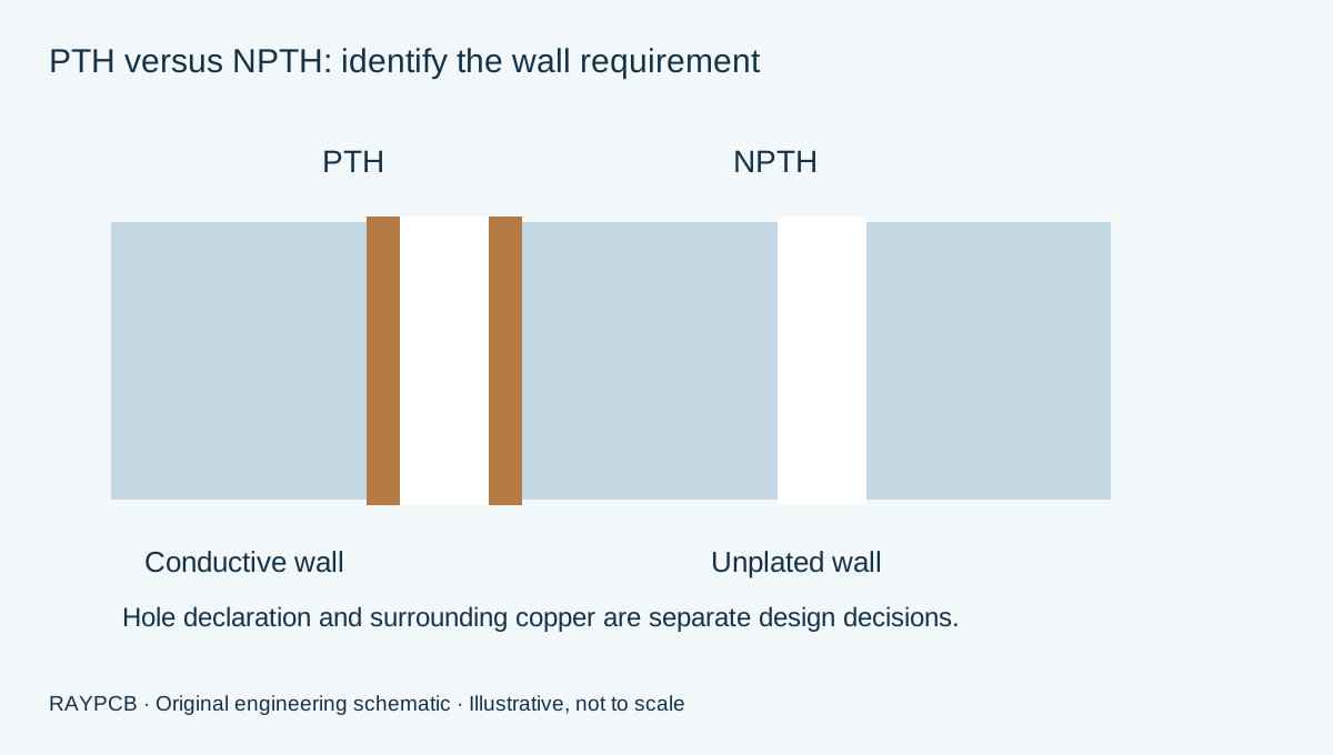
PTH vs NPTH: the difference is the conductive wall
A plated through hole, or PTH, has a conductive wall through the board thickness. It can connect intended copper layers or provide the conductive opening for a component lead. A non-plated through hole, or NPTH, has no specified conductive plating on its wall and is commonly used for mechanical clearance or location. The choice follows the feature's electrical and mechanical function, not simply whether it is round or has copper nearby.
Both categories can include nonround openings. An elongated plated opening is a plated slot; an unplated routed opening can serve a mechanical task. Likewise, a mounting hole is not automatically NPTH, and a visible copper ring does not by itself prove that the barrel is plated. A grounded mounting point requires an intentional connection design involving the board, hardware and enclosure.
This page helps you choose and communicate the hole type. It does not replace the PCB drilling process guide, which addresses how hole-making fits fabrication. The practical output here is a consistent set of CAD declarations, exported data and drawing notes that a receiving engineer can interpret without guessing.
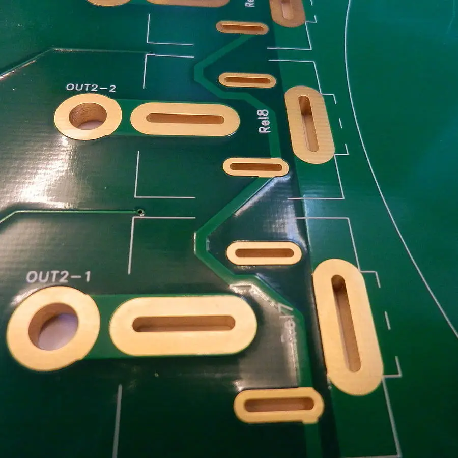
Compare the required function before choosing the pad
| Question | PTH starting point | NPTH starting point |
|---|---|---|
| Does the wall need to conduct? | Yes, with intentional layer connections | No conductive barrel is specified |
| Is a lead soldered through the board? | Review the lead, finished opening and land | Not a substitute for a required plated solder connection |
| Is the feature only mechanical clearance? | Use only if plating has a defined purpose | Usually the appropriate route to review |
| Does hardware provide grounding? | One possible architecture, not automatic | May coexist with a separate intentional surface contact |
| What data must be explicit? | Plating, finished size, connected layers and acceptance | Nonplated status, finished contour and copper keepouts |
| What remains outside the label? | Fit, current capacity and reliability | Strength, positioning and electrical isolation |
Begin by writing one sentence describing the hole's purpose. For example, “This opening allows a plastic locating peg to pass through without electrical contact” points toward a mechanical-hole definition. “This opening carries a soldered blade connected to two specified layers” points toward a plated feature. “This screw grounds the chassis” is incomplete until the actual contact surfaces and conductive path are identified.
Do not let a copied footprint make the decision silently. A library pad may include a net, copper layers, mask behavior and drill settings inherited from another component. Review those properties against the current function. A footprint can look plausible while carrying the wrong manufacturing declaration. The electrical schematic and mechanical drawing should agree about any intentional connection through the hardware.
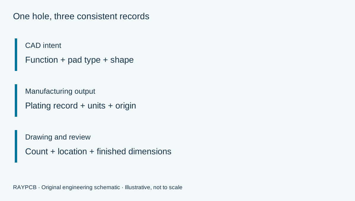
Keep hole type separate from surrounding copper
In CAD, the pad type describes how the feature participates in the board and its outputs. Its copper shape, drill shape and layer connections provide additional information. A mechanical hole near a copper area needs a defined clearance even when it has no electrical net. A plated hole needs a suitable surrounding land and connections on the intended layers. Treat these as related but separate design decisions.
For an electrical hole, inspect connected and nonconnected layers independently. A via or terminal can intentionally connect some layers while clearing others. The absence of a surface trace does not mean that an internal connection is absent. Conversely, a ring visible on the top surface may have no reliable conductive path to the intended internal plane if the design or export is wrong.
For a mechanical hole, review the full hardware envelope. A screw head or washer is larger than the hole through which the shank passes. Its possible movement and contact area can matter more than the nominal drill diameter. The wall being unplated does not make nearby copper safe to touch, nor does it create an electrical insulation rating. Keep the product's mechanical and safety requirements distinct from the pad declaration.
Check your hole and file declarations
Use the release-record checker to compare a stated function with the selected CAD pad type and export evidence. It flags a deterministic mismatch between mechanical-clearance intent and a plated pad, or electrical-interconnect intent and an unplated pad. Grounded hardware remains an engineering decision because more than one architecture can be valid. Unchecked output records remain open items rather than being treated as failures of the physical board.
RAYPCB ENGINEERING
Mechanical FeaturesPTH and NPTH release-record checker
Loading PTH and NPTH release-record checker…
This tool is a manual review worksheet. It does not read, upload or parse your design files. Selecting “verified” records your statement that the corresponding check has been performed. Include the relevant export and drawing revision in the reference field. The downloadable note can help communicate the review, but it is not automated DFM evidence or approval of a manufactured part.
A useful review can start before all information is available. Choose the unresolved options where appropriate, then use the output to identify what remains to be checked. For a direct quotation, you can also go straight to Contact. There is no requirement to complete the worksheet or disclose proprietary CAD details to an analytics system before asking an engineering question.
Export data that preserves plating intent
The receiving CAM system must be able to distinguish plated and nonplated features. Separate files are one common approach; an agreed combined format with correctly interpreted metadata can be another. File naming alone should not be the only evidence. Confirm the exported contents, declared units and coordinate origin, and include a drill map or table that makes the intended feature count visible.
The KiCad PCB Editor manual documents separate PTH and NPTH export settings and options for representing oval holes. These are software-output choices, not universal manufacturing limits. Use the options agreed with the receiver, and reopen the generated output. A slot visible in the editor is not proven present in every output format or every software version merely because the export completed.
For a file-level handoff, the PCB manufacturing file-format guide covers the wider fabrication package. Keep the board outline, copper, holes and drawing on one revision. Mixing a current hole file with an older copper export can create a package in which each individual file looks reasonable while the combination is incorrect.
Finished hole size is not always the shop tool size
State whether a dimension describes the finished opening. The fabricator may need machining compensation to achieve that opening after subsequent operations. A CAM exchange field called tool diameter does not necessarily mean the physical drill bit that will be used. The meaning must come from the selected format and the agreed handoff convention, not from the field name alone.
Ucamco's XNC specification is an authoritative reference for that format's definitions. Keep the finished-dimension convention in the drawing so it remains understandable outside a specific CAD tool. Where an existing workflow intentionally expects a different basis, document that exception clearly and avoid applying the same compensation twice.
Position is a separate requirement from diameter. A correctly sized locating hole can still be in the wrong place relative to the connector or enclosure. Agree the datum system, orientation and relevant positional tolerance. Reopening all outputs together is particularly valuable after a panel-origin change or a mirrored-view operation. A drawing's bottom view must not become an accidental mirrored manufacturing coordinate system.
Three practical review cases
Consider a plastic locating peg with no electrical function. The opening can be declared NPTH, but the designer still needs the maximum peg envelope, hole-size interval, location and board-edge relationship. Copper keepout should consider the peg and any nearby support hardware. Changing the hole to PTH because the library offers a convenient pad shape adds a new electrical and manufacturing condition without solving the mechanical fit.
Now consider a rectangular blade terminal. Its conductive wall requirement suggests a plated slot, and its lead envelope requires a nonround fit review. A large round hole is not automatically an equivalent replacement: land shape, solder volume, terminal support and neighboring spacing change. Continue with the plated-slot drawing guide for the finished-width and overall-length convention.
Finally, consider a chassis-ground screw. The required current path might involve a surface contact, a plated barrel, a washer, a metal standoff or several of these. Identify the intended contact interfaces and what happens under tolerance, coating, wear and assembly variation. The tool leaves this case open for engineering review because selecting PTH alone cannot prove the connection will work throughout product life.
Reconcile the records before manufacture
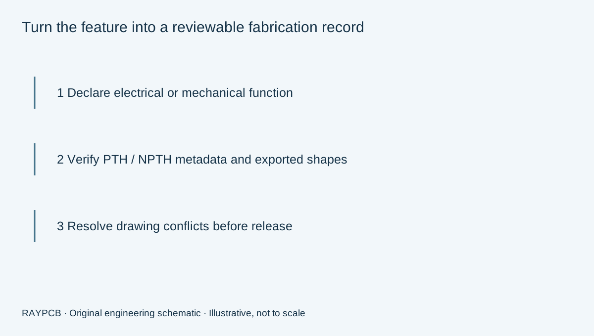
Review the exact exported package independently of the editor view. Count the plated and nonplated feature groups, inspect nonround shapes, overlay them with the copper and board outline, and compare the result with the drawing table. Investigate duplicates and missing features instead of treating a larger drill count as harmless. A feature represented twice can cause a different machining instruction, not merely redundant documentation.
If the output and drawing disagree, obtain one explicit resolution and update the release package. Do not rely on an informal note that never reaches the next purchase order. The PCB DFM page can support review of copper, hole and mechanical relationships. For an enquiry, send the files, revision, quantity and specific uncertainty through Contact.
The final record should distinguish design intent, manufacturing acceptance and assembly fit. A passed electrical test is useful for the specified network but does not establish every hole's mechanical clearance. A good dimensional result does not establish wall metallization quality. Agree the evidence appropriate to the feature rather than assuming one test covers every requirement.
PTH and NPTH questions
Is a mounting hole always nonplated?
No. Its electrical purpose and hardware arrangement determine the appropriate construction. A purely mechanical clearance hole and a deliberately grounded mounting interface should not inherit the same declaration without review.
Can a hole have a copper ring and still be NPTH?
The surrounding copper and the hole-wall plating are separate design conditions. Any such arrangement must have intentional clearances and a clear manufacturing declaration. The visible ring alone is not a reliable way to classify the wall.
Should PTH and NPTH always use separate files?
Use the agreed receiver workflow. Separate sets make the distinction explicit, while some combined formats can carry verified plating information. In either case, inspect the export and document the units, origin and feature interpretation.
Does the checker prove my files are correct?
No. It records and compares your declarations. Actual file inspection, manufacturing review and product acceptance remain separate activities. Keep the exported files and evidence with the worksheet if you use it in a release record.
Review the mechanical feature with RAYPCB
Send the board revision, construction, quantity and the mechanical feature or tolerance question you need reviewed. Identify unresolved requirements so the response can address them.
Send requirements for reviewOptional: attach the downloaded worksheet manually. This guidance does not certify a design, approve a shipment or replace the applicable authorized standards.